1987 SUZUKI GRAND VITARA warning
[x] Cancel search: warningPage 201 of 962
Coolant
The coolant recovery system is standard. The
coolant in the radiator expands with heat, and
the overflow is collected in the reservoir tank.
When the system cools down, the coolant is
drawn back into the radiator.
The cooling system has been filled at the factory
with a quality coolant that is either 50/50
mixture of water and GOLDEN CRUISER
1200 or 30/70 mixture of water and GOLDEN
CRUISER 1200.
The 50/50 mixture coolant solution provides
freezing protection to -36°C (-33”F), the
30/70 mixture coolant solution provides freezing.
protection to -16°C (3” F).
GOLDEN CRUISER 1200 - “Anti-freeze and
Summer Coolant” - its effects
1) Its freezing temperature is much lower and
depends on the concentration of GOLDEN
CRUISER 1200. It is an anti-freeze coolant.
2) It does not corrode the metal surfaces of the
cooling circuit.It is an anti-corrosion
coolant.
3) It does not develop foam or bubbles. It is a
foam-inhibited coolant.
When changing the engine coolant, use mixture
of 50% water and 50% GOLDEN CRUISER
1200 for the market where ambient tempera-
ture falls lower than -16°C (3°F) in winter and
mixture of 70% water and 30% GOLDEN
CRUISER 1200 for the market where am-
bient temperature doesn’t fall lower than -16°C
(3” F).
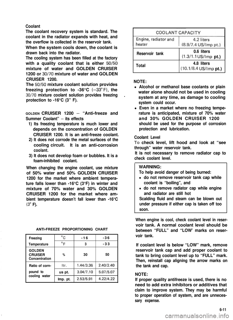
ANTI-FREEZE PROPORTIONING CHART
Freezing
Temperature
GOLDEN
CRUISERConcentration
OC-16-36
OF3-33
%3050
Ratio of corn-Itr.1.4413.362.4012.40
pound tous pt.3.04l7.10 5.0715.07cooling waterImp. pt.2.5315.914.221422
Reservoir tank0.6 liters
(1.3/1.1 US/Imp pt.)I
Total4.8 liters
(10.1/8.4 US/Imp pt.)
NOTE:
l Alcohol or methanol base coolants or plain
water alone should not be used in cooling
system at any time, as damage to cooling
system could occur.
l Even in a market where no freezing tempe-
rature is anticipated, mixture of 70% water
and 30% GOLDEN CRUISER 1200
should be used for the purpose of corrosion
protection and lubrication.
Coolant Level
,To check level, lift hood and look at “see
through” water reservoir tank.
It is not necessary to remove radiator cap to
check coolant level.
WARNING:
To help avoid danger of being burned:
l do not remove reservoir tank cap while
coolant is “boiling”, and
l do not remove radiator cap while engine
and radiator are still hot
Scalding fluid and steam can be blown out
under pressure if either cap is taken off too
soon.
When engine is cool, check coolant level in reser-
voir tank. A normal coolant level should be
between “FULL” and “LOW’ marks on reser-
voir tank.
If coolant level is below “LOW” mark, remove
reservoir tank cap and add proper coolant to
tank to bring coolant level up to “FULL” mark.
Then, reinstall cap aligning the arrow marks on
the tank and cap.
NOTE:
If proper quality antifreeze is used, there is no
need to add extra inhibitors or additives that
claim to improve system. They may be harmful
to proper operation of system, and are unneces-
sary expense.
6-11
Page 202 of 962
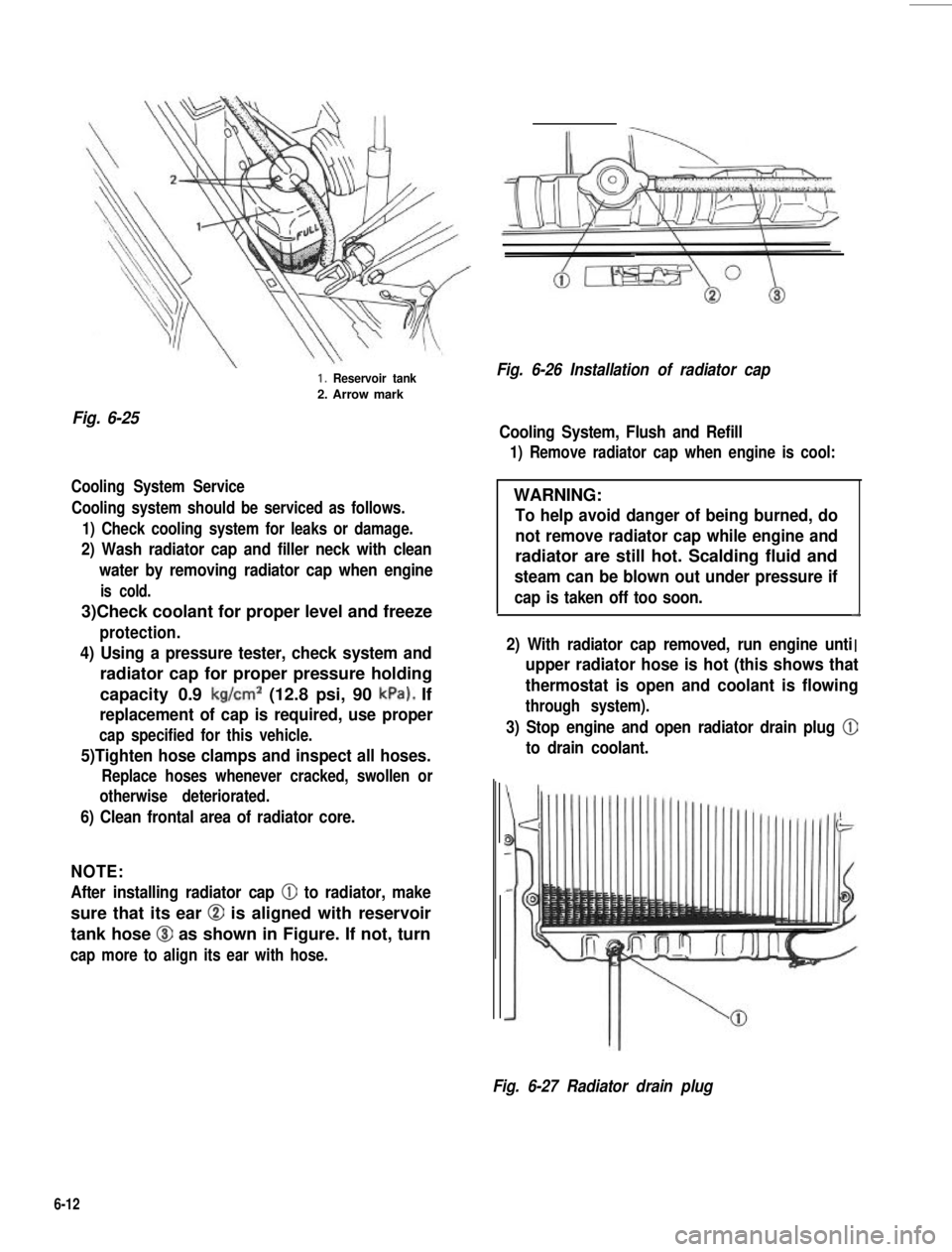
Fig. 6-25
1. Reservoir tank
2. Arrow mark
Cooling System Service
Cooling system should be serviced as follows.
1) Check cooling system for leaks or damage.
2) Wash radiator cap and filler neck with clean
water by removing radiator cap when engine
is cold.
3)Check coolant for proper level and freeze
protection.
4) Using a pressure tester, check system and
radiator cap for proper pressure holding
capacity 0.9 kg/cm2 (12.8 psi, 90 kPa). If
replacement of cap is required, use proper
cap specified for this vehicle.
5)Tighten hose clamps and inspect all hoses.
Replace hoses whenever cracked, swollen or
otherwise deteriorated.
6) Clean frontal area of radiator core.
NOTE:
After installing radiator cap 0 to radiator, make
sure that its ear @ is aligned with reservoir
tank hose @I as shown in Figure. If not, turn
cap more to align its ear with hose.
Fig. 6-26 Installation of radiator cap
Cooling System, Flush and Refill
1) Remove radiator cap when engine is cool:
WARNING:
To help avoid danger of being burned, do
not remove radiator cap while engine and
radiator are still hot. Scalding fluid and
steam can be blown out under pressure if
cap is taken off too soon.d
I2) With radiator cap removed, run engine unti. .upper radiator hose is hot (this shows that
thermostat is open and coolant is flowing
through system).
3) Stop engine and open radiator drain plug @
to drain coolant.
Fig. 6-27 Radiator drain plug
6-12
Page 208 of 962
![SUZUKI GRAND VITARA 1987 Service Repair Manual 7-4. REMOVAL AND INSTALLATION
Removal
[Heater and blower motor]
1. Disconnect battery negative cable.
2. Drain cooling system.
WARNING:
To help avoid the danger of being burned, do
not remove the drai SUZUKI GRAND VITARA 1987 Service Repair Manual 7-4. REMOVAL AND INSTALLATION
Removal
[Heater and blower motor]
1. Disconnect battery negative cable.
2. Drain cooling system.
WARNING:
To help avoid the danger of being burned, do
not remove the drai](/manual-img/20/57437/w960_57437-207.png)
7-4. REMOVAL AND INSTALLATION
Removal
[Heater and blower motor]
1. Disconnect battery negative cable.
2. Drain cooling system.
WARNING:
To help avoid the danger of being burned, do
not remove the drain plug and the radiator
cap while the engine and radiator are still hot.
Scalding fluid and steam can be blown out
under pressure if the plug and cap are taken
off too soon.
Fig 7-51. Drain plug2. Radiator
3. Disconnect heater inlet and outlet hoses
from heater unit pipes.
4. Remove instrument panel ass’y with speedo-
meter ass’y as follows.
1) Take off horn pad and remove steering
wheel using special tool @.
2) If equipped with radio and cigarette lighter,
disconnect radio and cigarette lighter lead
wires, and pull out radio case with radio
and cigarette lighter after loosening case
stay screw, and remove radio case bracket.
3) Pull out ashtray and loosen ashtray plate
screws.
4) Disconnect front food opening cable from
lock ass’y.
5) Loosen panel box stay screw and hood
opening cable lock nut on back side of
panel box cover.
6) Disconnect lead wires to control lever at
the coupler and heater control cables.
7) Pull out lever knobs and plate, and loosen
lever case screws.
8) Remove defroster and side ventilator hoses.
9) Disconnect lead wires to speedometer and
switches installed instrument panel at the
couplers.
10) Disconnect speedometer cable from speedo-
meter.
11) Release wire harness clamps installed to
instrument panel.
12) Loosen screws securing instrument panel.
13) Remove instrument panel.
NOTE:
l Before removing, recheck to ascertain all
hoses, wire harness, cables and screws are
disconnected from instrument paneL
l When removing heater lever case which is
fitted in steering column holder, be very
careful not to damage it
5. Remove steering column holder after loosen-
ing front door open stopper screws.
Fig. 7-7Fig. 7-6@ Special tool (Steering wheel
remover 09944-360 10)
7-5
Page 219 of 962
Ignition Timing
Ignition timing10” BTDC at
800 * 50 r/min
1 Ignition orderIl-3-4-2I
When checking and adjusting ignition timing,
be sure to use timing light (09900-27301 or
09900-27311).
NOTE:
Prior to check and adjustment of ignition timing,
make sure that head lights, heater fan, rear
defogger (if equipped), and air conditioner (if
equipped) are “OFF”. If any one of these
systems is “ON”,idle up system operates and
engine idle speed will be out of the specification.
[Checking]
1. Remove rubber plug from timing check
window on the transmission case.
2. Start engine and warm it up to normal operat-
ing temperature.
3. After warming up, check to be sure that idle
speed is within specification. If idle speed is
out of specification, adjust it by turning
idle speed adjusting screw of carburetor.
4. Connect timing light to high tension cord of
No. 1 cylinder.
5. With engine running at specified idle speed,
direct the timing light to timing check win-
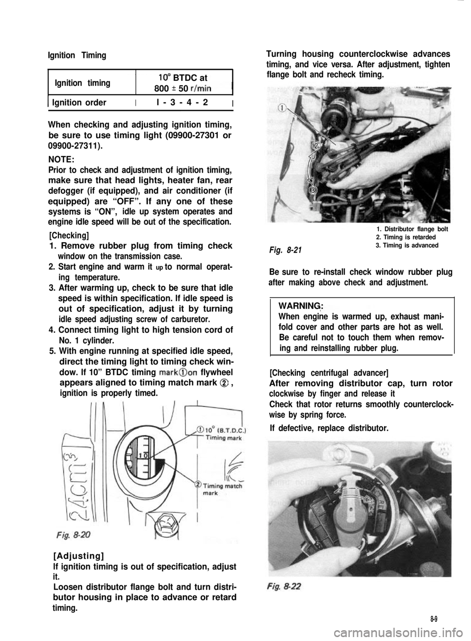
dow. If 10” BTDC timing mark@on flywheel
appears aligned to timing match mark @ ,
ignition is properly timed.
Fig. 8-20
[Adjusting]
lf ignition timing is out of specification, adjust
it.
Loosen distributor flange bolt and turn distri-
butor housing in place to advance or retard
timing.
Turning housing counterclockwise advances
timing, and vice versa. After adjustment, tighten
flange bolt and recheck timing.
Fig. 8-21
1. Distributor flange bolt
2. Timing is retarded
3. Timing is advanced
Be sure to re-install check window rubber plug
after making above check and adjustment.
WARNING:
When engine is warmed up, exhaust mani-
fold cover and other parts are hot as well.
Be careful not to touch them when remov-
ing and reinstalling rubber plug.
[Checking centrifugal advancer]
After removing distributor cap, turn rotor
clockwise by finger and release it
Check that rotor returns smoothly counterclock-
wise by spring force.
If defective, replace distributor.
Fig. 8-22
8-9
Page 354 of 962
17-3. MAINTENANCE SERVICES
Shock Absorber
1) Inspect for deformation or damage.
2) Inspect bushings for wear or damage.
3) Inspect for evidence of oil leakage.
Replace any defective part.
WARNING:
When handling rear shock absorber in which
high-pressure gas is sealed, make sure to
observe the following precautions.
1) Don’t disassemble it.
2) Don’t put it into the fire.
3) Don’t store it where it gets hot.
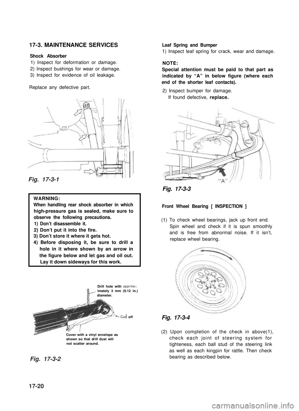
4) Before disposing it, be sure to drill a
hole in it where shown by an arrow in
the figure below and let gas and oil out.
Lay it down sideways for this work.
Drill hole with approx-imately 3 mm (0.12 in.)diameter.
‘-cut off
Cover with a vinyl envelope asshown so that drill dust willnot scatter around.
Leaf Spring and Bumper
1) Inspect leaf spring for crack, wear and damage.
NOTE:
Special attention must be paid to that part as
indicated by “A” in below figure (where each
end of the shorter leaf contacts).
2) Inspect bumper for damage.
If found defective, replace.
Fig. 17-3-3
Front Wheel Bearing [ INSPECTION ]
(1) To check wheel bearings, jack up front end.
Spin wheel and check if it is spun smoothly
and is free from abnormal noise. If it isn’t,
replace wheel bearing.
Fig. 17-3-4
(2) Upon completion of the check in above(1),
check each joint of steering system for
tighteness, each ball stud of the steering link
as well as each kingpin for rattle. Then check
bearing as described below.
Fig. 17-3-1
Fig. 17-3-2
17-20
Page 384 of 962
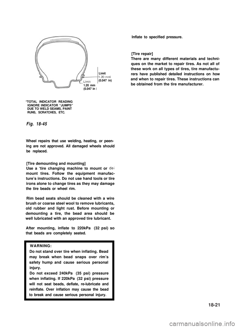
/I
d-
Limitl.Mmm(0.047 in)
1.20 mm(0.047 in 1
*TOTAL INDICATOR READINGIGNORE INDICATOR “JUMPS”DUE TO WELD SEAMS, PAINTRUNS, SCRATCHES, ETC.
Fig. 18-45
Wheel repairs that use welding, heating, or peen-
ing are not approved. All damaged wheels should
be replaced.
[Tire demounting and mounting]
Use a ‘tire changing machine to mount or de-
mount tires. Follow the equipment manufac-
ture’s instructions. Do not use hand tools or tire
irons alone to change tires as they may damage
the tire beads or wheel rim.
Rim bead seats should be cleaned with a wire
brush or coarse steel wool to remove lubricants,
old rubber and light rust. Before mounting or
demounting a tire, the bead area should be
well lubricated with an approved tire lubricant.
After mounting, inflate to 220kPa (32 psi) so
that beads are completely seated.
WARNING:
Do not stand over tire when inflating. Bead
may break when bead snaps over rim’s
safety hump and cause serious personal
injury.
Do not exceed 240kPa (35 psi) pressure
when inflating. If 220kPa (32 psi) pressure
will not seat beads, deflate, re-lubricate and
reinflate. Over inflation may cause the bead
to break and cause serious personal injury.1
Inflate to specified pressure.
[Tire repair]
There are many different materials and techni-
ques on the market to repair tires. As not all of
these work on all types of tires, tire manufactu-
rers have published detailed instructions on how
and when to repair tires. These instructions can
be obtained from the tire manufacturer.
18-21
Page 386 of 962

SECTION 19
BRAKES
CONTENTS
19-1. GENERAL DESCRIPTION................................. 19-2
19-2. FRONT DISC BRAKE..................................... 19-14
19-3. REAR DRUM BRAKE..................................... 19-20
19-4. MASTER CYLINDER..................................... 19-27
19-5. BRAKE BOOSTER....................................... 19-30
19-6. PARKING BRAKE........................................ 19-38
19-7. BRAKE PIPES AND HOSES . . . . . . . . . . . . . . . . . . . . . . . . . . . . . . . 19-39
19-8. MAINTENANCE SERVICE . . . . . . . . . . . . . . . . . . . . . . . . . . . . . . . . 19-42
19-9. TORQUE SPECIFICATION.. . . . . . . . . . . . . . . . . . . . . . . . . . . . . . . 19-49
NOTE:
All brake fasteners are important attaching parts in that they could affect the performance
of vital parts and systems, and/or could result in major repair expense. They must be
replaced with one of same part number or with an equivalent part if replacement becomes
necessary. Do not use a replacement part of lesser quality or substitute design. Torque
values must be used as specified during reassembly to assure proper retention of all parts.
There is to be no welding as it may result in extensive damage and weakening of the
metal.
WARNING:
When servicing wheel brake parts, do not create dust by grinding, sanding brake linings,
or by cleaning wheel brake parts with a dry brush or with compressed air. Many wheel
brake parts contain asbestos fibers which can become airborned if dust is created dur-
ing servicing. Breathing dust containing asbestos fibers may cause serious bodily harm.
A water dampened cloth or water based solution should be used to remove any dust
on brake parts. Equipment is commercially available to perform this washing function.
These wet methods will prevent asbestos fibers from becoming airborne.
19-1
Page 393 of 962
![SUZUKI GRAND VITARA 1987 Service Repair Manual DRUM BRAKE ASSEMBLY (Rear Wheel Brake)
[GENERAL DESCRIPTION]
The drum brake assembly has a self shoe clearance adjusting system so that drum-to-shoe clearance is
maintained appropriate at all times. F SUZUKI GRAND VITARA 1987 Service Repair Manual DRUM BRAKE ASSEMBLY (Rear Wheel Brake)
[GENERAL DESCRIPTION]
The drum brake assembly has a self shoe clearance adjusting system so that drum-to-shoe clearance is
maintained appropriate at all times. F](/manual-img/20/57437/w960_57437-392.png)
DRUM BRAKE ASSEMBLY (Rear Wheel Brake)
[GENERAL DESCRIPTION]
The drum brake assembly has a self shoe clearance adjusting system so that drum-to-shoe clearance is
maintained appropriate at all times. For details, refer to OPERATION in the next page.
NOTE:
Replace all components included in repair kits used to service this drum brake. Lubricate parts as specified.
WARNING:
When servicing wheel brake parts, do not create dust by grinding or sanding brake linings or by clean-
ing wheel brake parts with a dry brush or with compressed air. (A water dampened cloth should be
used.) Many wheel brake parts contain asbestos fibers which can become airborne if dust is created
during servicing Breathing dust containing asbestos fibers may cause serious bodily harm. If any
hydraulic component is removed or brake line disconnected, bleed the brake system. The torque
values specified are for dry, unlubricated fasteners.
1. Brake back plate
2. Brake shoe
3. Shoe return spring (A)4. Brake strut rod
5. Shoe return spring (B)
6. Rod spring7. Shoe hold down spring
8. Shoe hold down pin
9. Wheel cylinder10. Stopper plateiI7
Fig. 19-8
19-8