1987 SUZUKI GRAND VITARA warning
[x] Cancel search: warningPage 51 of 962

Condition
Excessive pedal travel
(Pedal stroke too
large)
Possible cause
1. Partial brake system failure
2. Insufficient fluid in master
cylinder reservoirs
Correction
Check diagonal brake systems and
repair as necessary
Fill reservoirs with approved brake
fluid. Check for leaks and air in
brake systems. Check warning light.
Bleed system if necessary.
3. Air in system (Pedal soft/spongy)Bleed system
4. Rear brake system not adjustedAdjust rear brakes (Repair auto
(malfunctioning auto adjustingadjusting mechanism)
mechanism)
5. Bent brake shoesReplace brake shoes
6. Worn rear brake shoesReplace brake shoes.
Dragging brakes (A
very light drag is pre-
sent in all disc brakes
immediately after
pedal is released)
1. Master cylinder pistons not
returning correctly
2. Clogged return port in master
cylinder
3. Restricted brake tubes or hoses
4. Incorrect parking brake
adjustment
5. Weakened or broken return
springs in the brake
Repair master cylinder
Clean
Check for soft hoses or damaged tubes
and replace with new hoses and/or
new double-walled steel brake tubing
Check and adjust to correct specifica-
tions
Replace
6. Sluggish parking-brake cables or
linkage
Repair or replace
7. Wheel cylinder or caliper piston
sticking
Repair as necessary
Pedal pulsation1. Damaged or loose wheel bearingsReplace wheel bearings
(Pedal pulsates when2. Excessive disc lateral runout Check per instructions. If not within
depressed for braking)specifications, replace or machine the
disc.
3. Parallelism not within specifica-Check per instructions. If not within
tionsspecifications, replace or machine the
disc.
4. Rear drums out of roundCheck runout.
Braking noise1. Glazed shoe linings, or foreignRepair or replace shoe lining
matters stuck to linings
2. Worn or distorted shoe liningsReplace shoe lining (or pad)
3. Loose front wheel bearingsReplace wheel bearings
4. Distorted backing plates or looseReplace or retighten securing bolts
mounting bolts
2-13
Page 127 of 962
REMOVAL AND INSTALLATION
Removal and installation of carburetor
place where no fire is used around.
Removal
1) Disconnect negative battery cord from
battery.
2) Drain coolant.
WARNING:
To help avoid the danger of being burned,
do not remove the drain plug and the
radiator cap while the engine and radiator
are still hot. Scalding fluid and steam can
be blown out under pressure if the plug
and cap are taken off too soon.
3) Remove air intake case from carburetor.
4) Disconnect micro switches, switch vent sole-
noid valve, fuel cut solenoid valve and MCSV
lead wires at their couplers.
5) Disconnect VSV coupler from VSV.
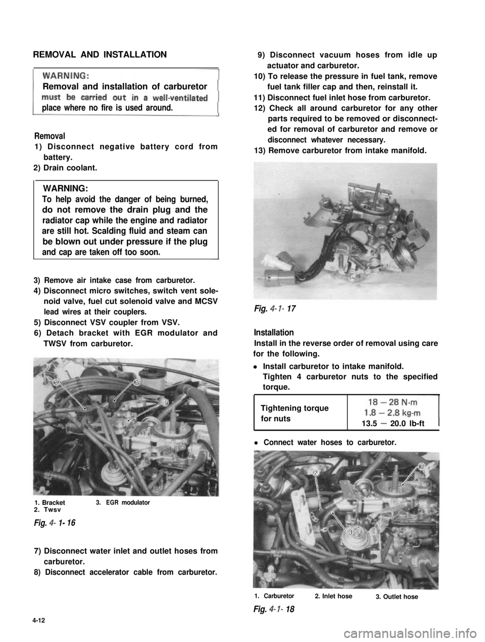
6) Detach bracket with EGR modulator and
TWSV from carburetor.
1. Bracket3.EGRmodulator2. Twsv
Fig. 4- 1-16
7) Disconnect water inlet and outlet hoses from
carburetor.
8) Disconnect accelerator cable from carburetor.
9) Disconnect vacuum hoses from idle up
actuator and carburetor.
10) To release the pressure in fuel tank, remove
fuel tank filler cap and then, reinstall it.
11) Disconnect fuel inlet hose from carburetor.
12) Check all around carburetor for any other
parts required to be removed or disconnect-
ed for removal of carburetor and remove or
disconnect whatever necessary.
13) Remove carburetor from intake manifold.
Fig. 4- 7- 17
Installation
Install in the reverse order of removal using care
for the following.
l Install carburetor to intake manifold.
Tighten 4 carburetor nuts to the specified
torque.
Tightening torque
for nuts13.5 - 20.0 lb-ft
l Connect water hoses to carburetor.
1. Carburetor
Fig. 4- I- 18
2. Inlet hose3. Outlet hose
4-12
Page 150 of 962
![SUZUKI GRAND VITARA 1987 Service Repair Manual [Fuel tank purging procedure]
WARNING:
This purging procedure will NOT remove
all fuel vapor. Do not attempt any repair
on tank where heat or flame is required, as
an explosion resulting in personal i SUZUKI GRAND VITARA 1987 Service Repair Manual [Fuel tank purging procedure]
WARNING:
This purging procedure will NOT remove
all fuel vapor. Do not attempt any repair
on tank where heat or flame is required, as
an explosion resulting in personal i](/manual-img/20/57437/w960_57437-149.png)
[Fuel tank purging procedure]
WARNING:
This purging procedure will NOT remove
all fuel vapor. Do not attempt any repair
on tank where heat or flame is required, as
an explosion resulting in personal injury
cou Id occur.J
The following procedure is used for purging the
fuel tank.
1) After removing fuel tank, remove all hoses,
fuel level gauge from fuel tank.
2) Drain all remaining fuel from tank.
3) Move tank to flushing area.
4) Fill tank with warm water or tap water, and
agitate vigorously and drain. Repeat this
washing until inside of tank is clean.
Replace tank if inside is rusty.
5) Completely flush out remaining water after
washing.
[ Installation]
Reverse removal procedure for installation using
care for the following.
Tightening torque30-45 Nm
for fuel tank(3.0- 4.5 kg-m)
drain plug(22.0 - 32.5 lb-ft)
Refer to Fig. 4-2-5 for piping and clamp posi-
tions.
l Make sure for correct hose-to-pipe connec-
tion.
l Clamp hoses securely.
l Upon completion of installation, start engine
and check hose joints for leaks.
MAINTENANCE SERVICES
Fuel Lines
Visually inspect fuel lines and connections for
evidence of fuel leakage, hose cracking, and
damage. Make sure all clamps are secure.
Repair leaky joints, if any.
Replace hoses that are suspected of being crack-
ed.
Fig. 4-2-14
Fuel Filler (tank) Cap
Visually inspect gasket of fuel filler cap.
If it is damaged or deteriorated, replace filler cap
with new one.
NOTE:
If cap requires replacement, only a cap with
the same features should be used. Failure to
use correct cap can result in a serious malfunc-
tion of the system.
Fig. 4-2-15
1. Fuel filler cap
2. Fuel filler capgasket
Fuel Filter
As said before, this filter does not permit dis-
assembly: it is to be replaced with a new one
periodically.
Replace fuel filter referring to previous item of
“Fuel Filter Removal and Installation”.
This servicing must be performed in a well
ventilated area and away from any open
flames (such as gas hot water heaters).
4-35
Page 169 of 962
5-3. MAINTENANCE SERVICE
GENERAL
If the emission control hoses were disconnected
and any system component was removed for
service,be sure to reinstall the component
properly and route and connect hoses correctly
after service. Refer to Fig. 5-l-l for hose con-
nection.
PCV SYSTEM
Checking PCV System
NOTE:
If the engine is idling rough, this may be caused
by a stuck PCV valve, plugged hoses or vacuum
leakage of PCV line, therefore, never adjust the
carburetor idle without first checking the PCV
valve and hoses.
[ PCV hoses]
Check hoses for connection, leakage, clog, and
deterioration. Replace as necessary.
[ PCV valve]
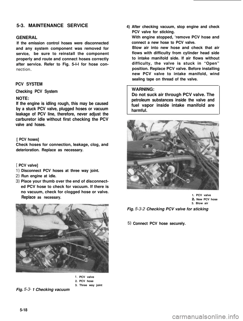
Disconnect PCV hoses at three way joint.
Run engine at idle.
Place your thumb over the end of disconnect-
ed PCV hose to check for vacuum. If there is
no vacuum, check for clogged hose or valve.
Replace as necessary.
4) After checking vacuum, stop engine and check
PCV valve for sticking.
With engine stopped, ‘remove PCV hose and
connect a new hose to PCV valve.
Blow air into new hose and check that air
flows with difficulty from cylinder head side
to intake manifold side. If air flows without
difficulty, the valve is stuck in “Open”
position. Replace PCV valve. Before installing
new PCV valve to intake manifold, wind
sealing tape on thread of the valve.
WARNING:
Do not suck air through PCV valve. The
petroleum substances inside the valve and
fuel vapor inside intake manifold are
harmful.
1. PCV valve
2. New PCV hose3. Blow air
Fig. 5-3-2 Checking PCV valve for sticking
5) Connect PCV hose securely.
1. PCV valve
2. PCV hose
3. Three way joint
Fig. 5-3- 1 Checking vacuum
5-18
Page 188 of 962
EXHAUST GAS RECIRCULATION (EGR)
SYSTEM
Checking EGR system
NOTE:
1)
Before checking, confirm that altitude is not
higher than 1,220 m (4,000 ft) (atmospheric
pressure is below 680mmHg) and gear shift
lever is at neutral position.
When performing this check at higher than
1,220 m (4,000 ft) altitude, be sure to dis-
connect HAC coupler.
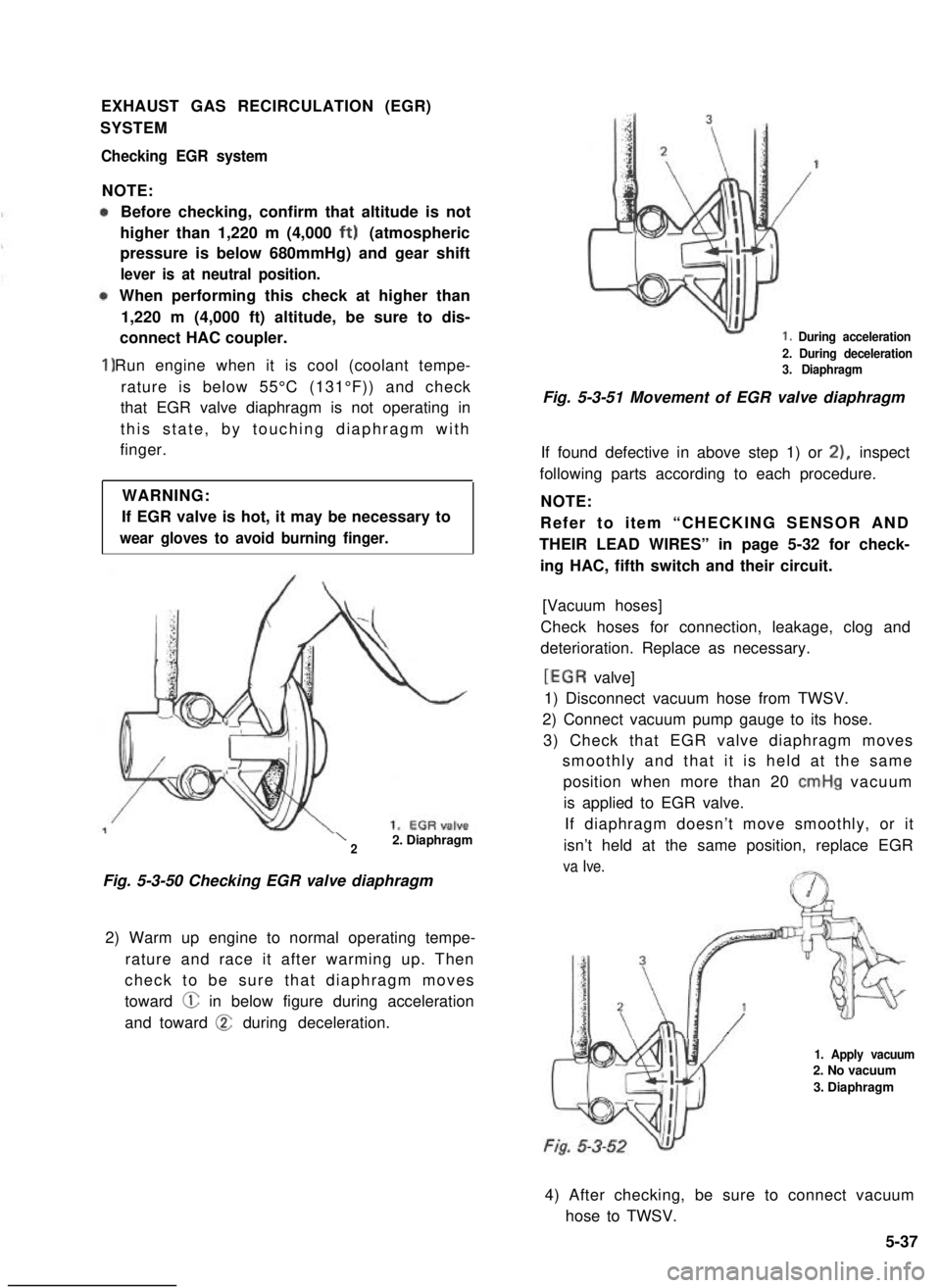
Run engine when it is cool (coolant tempe-
rature is below 55°C (131°F)) and check
that EGR valve diaphragm is not operating in
this state, by touching diaphragm with
finger.
WARNING:
If EGR valve is hot, it may be necessary to
wear gloves to avoid burning finger.
\22. Diaphragm
Fig. 5-3-50 Checking EGR valve diaphragm
2) Warm up engine to normal operating tempe-
rature and race it after warming up. Then
check to be sure that diaphragm moves
toward @ in below figure during acceleration
and toward @ during deceleration.
1. During acceleration
2. During deceleration3. Diaphragm
Fig. 5-3-51 Movement of EGR valve diaphragm
If found defective in above step 1) or 21, inspect
following parts according to each procedure.
NOTE:
Refer to item “CHECKING SENSOR AND
THEIR LEAD WIRES” in page 5-32 for check-
ing HAC, fifth switch and their circuit.
[Vacuum hoses]
Check hoses for connection, leakage, clog and
deterioration. Replace as necessary.
[EGR valve]
1) Disconnect vacuum hose from TWSV.
2) Connect vacuum pump gauge to its hose.
3) Check that EGR valve diaphragm moves
smoothly and that it is held at the same
position when more than 20 cmHg vacuum
is applied to EGR valve.
If diaphragm doesn’t move smoothly, or it
isn’t held at the same position, replace EGR
va Ive.
1. Apply vacuum2. No vacuum
3. Diaphragm
4) After checking, be sure to connect vacuum
hose to TWSV.
5-37
Page 193 of 962
Radiator Cap
A pressure-vent cap is used on the radiator. The
cap contains a pressure valve and vacuum valve.
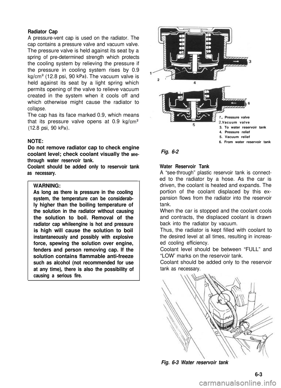
The pressure valve is held against its seat by a
spring of pre-determined strength which protects
the cooling system by relieving the pressure if
the pressure in cooling system rises by 0.9
kg/cm2 (12.8 psi, 90 kPa). The vacuum valve is
held against its seat by a light spring which
permits opening of the valve to relieve vacuum
created in the system when it cools off and
which otherwise might cause the radiator to
collapse.
The cap has its face marked 0.9, which means
that its pressure valve opens at 0.9 kg/cm2
(12.8 psi, 90 kPa).
NOTE:
Do not remove radiator cap to check engine
coolant level; check coolant visually the see-
through water reservoir tank.
Coolant should be added only to reservoir tank
as necessary.
4
WARNING:
As long as there is pressure in the cooling
system, the temperature can be considerab-
ly higher than the boiling temperature of
the solution in the radiator without causing
the solution to boil. Removal of the
radiator cap whileengine is hot and pressure
is high will cause the solution to boil
instantaneously and possibly with explosive
force, spewing the solution over engine,
fenders and person removing cap. If the
solution contains flammable anti-freeze
such as alcohol (not recommended for use
at any time), there is also the possibility of
causing a serious fire.
2’
I6
. Pressure valve
Vacuum valve
3. To water reservoir tank4. Pressure relief5. Vacuum relief
6. From water reservoir tank
Fig. 6-2
Water Reservoir Tank
A “see-through” plastic reservoir tank is connect-
ed to the radiator by a hose. As the car is
driven, the coolant is heated and expands. The
portion of the coolant displaced by this ex-
pansion flows from the radiator into the reservoir
tank.
When the car is stopped and the coolant cools
and contracts, the displaced coolant is drawn
back into the radiator by vacuum.
Thus, the radiator is kept filled with coolant to
the desired level at all times, resulting in increas-
ed cooling efficiency.
Coolant level should be between “FULL” and
“LOW’ marks on the reservoir tank.
Coolant should be added only to the reservoir
tank as necessary.
Fig. 6-3 Water reservoir tank
6-3
Page 195 of 962
6-2. .REMOVAL
WARNING:
l Check to make sure that cooling water
temperature is cold before removing any
part of cooling system components.
l Also be sure to disconnect 0 cord from
battery 0 terminal before removing any
part.
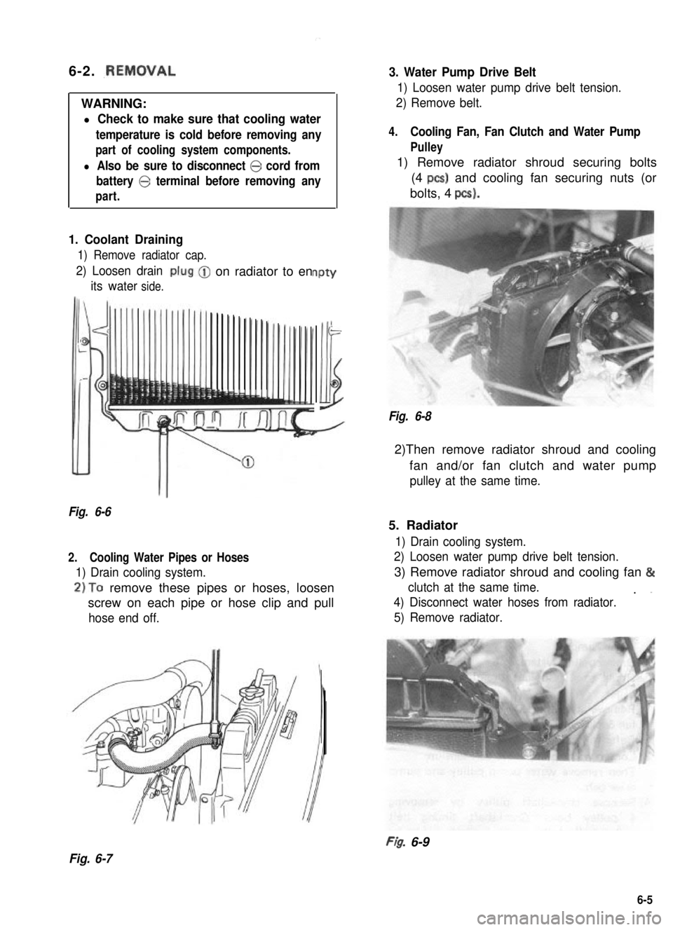
1. Coolant Draining
1) Remove radiator cap.
2) Loosen drain
its waterside.
-on radiator to enPtY
-
Illi
Fig. 6-6
2.Cooling Water Pipes or Hoses
1) Drain cooling system.
2)To remove these pipes or hoses, loosen
screw on each pipe or hose clip and pull
hose end off.
3. Water Pump Drive Belt
1) Loosen water pump drive belt tension.
2) Remove belt.
4.Cooling Fan, Fan Clutch and Water Pump
Pulley
1) Remove radiator shroud securing bolts
(4 PCS) and cooling fan securing nuts (or
bolts, 4 pcs).
Fig. 6-8
2)Then remove radiator shroud and cooling
fan and/or fan clutch and water pump
pulley at the same time.
5. Radiator
1) Drain cooling system.
2) Loosen water pump drive belt tension.
3) Remove radiator shroud and cooling fan &
clutch at the same time.. ”
4) Disconnect water hoses from radiator.
5) Remove radiator.
FI& 6-9
Fig. 6-7
6-5
Page 200 of 962
Radiator6-5. MAINTENANCE SERVICE
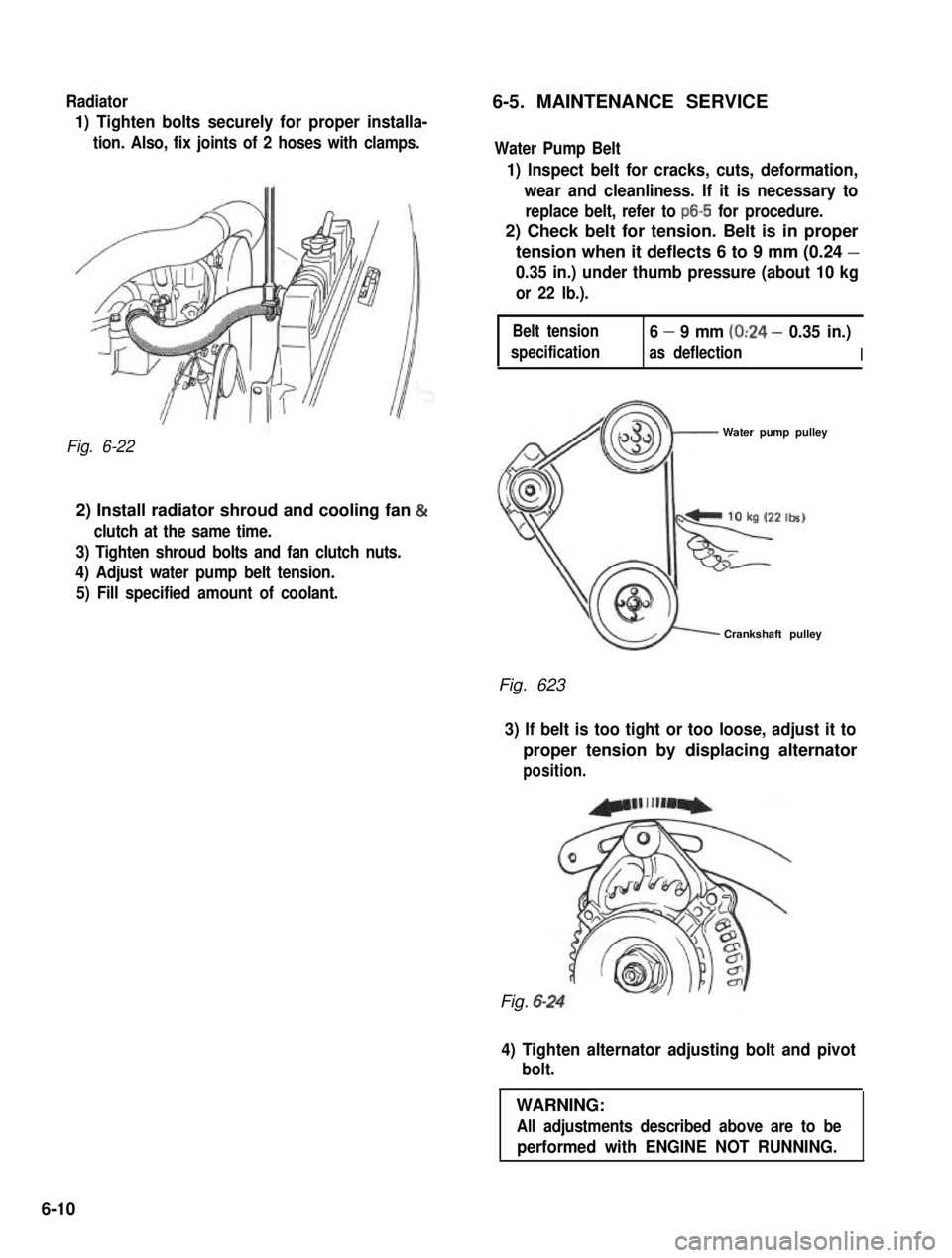
1) Tighten bolts securely for proper installa-
tion. Also, fix joints of 2 hoses with clamps.
Fig. 6-22
2) Install radiator shroud and cooling fan &
clutch at the same time.
3) Tighten shroud bolts and fan clutch nuts.
4) Adjust water pump belt tension.
5) Fill specified amount of coolant.
Water Pump Belt
1) Inspect belt for cracks, cuts, deformation,
wear and cleanliness. If it is necessary to
replace belt, refer to ~6-5 for procedure.
2) Check belt for tension. Belt is in proper
tension when it deflects 6 to 9 mm (0.24 -
0.35 in.) under thumb pressure (about 10 kg
or 22 lb.).
Belt tension
specification
6 - 9 mm (0:24 - 0.35 in.)
as deflectionI
Water pump pulley
Crankshaft pulley
Fig. 623
3) If belt is too tight or too loose, adjust it to
proper tension by displacing alternator
position.
Fig. 6-
4) Tighten alternator adjusting bolt and pivot
bolt.
WARNING:
All adjustments described above are to be
performed with ENGINE NOT RUNNING.
6-10