1987 SUZUKI GRAND VITARA warning
[x] Cancel search: warningPage 400 of 962
Caliper
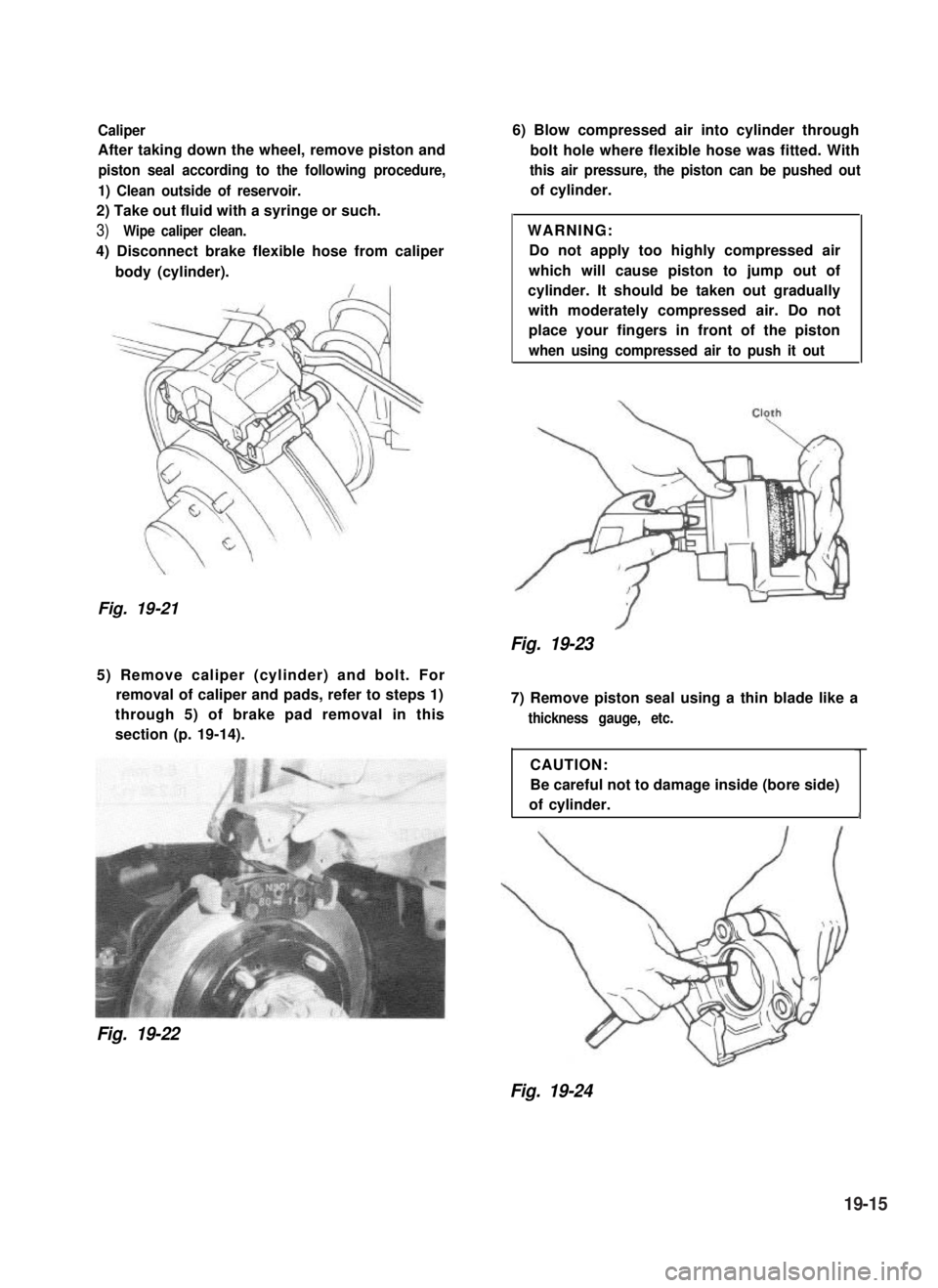
After taking down the wheel, remove piston and
piston seal according to the following procedure,
1) Clean outside of reservoir.
2) Take out fluid with a syringe or such.
3)Wipe caliper clean.
4) Disconnect brake flexible hose from caliper
body (cylinder).
Fig. 19-21
6) Blow compressed air into cylinder through
bolt hole where flexible hose was fitted. With
this air pressure, the piston can be pushed out
of cylinder.
WARNING:
Do not apply too highly compressed air
which will cause piston to jump out of
cylinder. It should be taken out gradually
with moderately compressed air. Do not
place your fingers in front of the piston
when using compressed air to push it out
Fig. 19-23
5) Remove caliper (cylinder) and bolt. For
removal of caliper and pads, refer to steps 1)
through 5) of brake pad removal in this
section (p. 19-14).
Fig. 19-22
7) Remove piston seal using a thin blade like a
thickness gauge, etc.
CAUTION:
Be careful not to damage inside (bore side)
of cylinder.1
Fig. 19-24
19-15
Page 427 of 962
19-8. MAINTENANCE SERVICE
ROAD TESTING BRAKES
Brakes should be tested on dry, clean, smooth
and reasonably level roadway which is not
crowned. Road test brakes by making brake
applications with both light and heavy pedal
forces at various speeds to determine if the car
stops evenly and effectively.
Also drive car to see if it leads to one side or the
other without brake application. If it does,
check tire pressure, front end alignment and
front suspension attachments for looseness.
See diagnosis chart for other causes.
BRAKE FLUID LEAKS
Check master cylinder fluid levels. While a slight
drop in reservoir level does result from normal
lining wear, an abnormally low level indicates a
leak in the system.In such a case, check the
entire brake system for leakage. If even a slight
evidence of leakage is noted, the cause should be
corrected or defective parts should be replaced.
BRAKE FLUID LEVEL INSPECTION
Be sure to use particular brake fluid either as
marked on reservoir cap of that car or recom-
mended in owner’s manual which comes along
with that car.
Use of any other fluid is strictly prohibited.
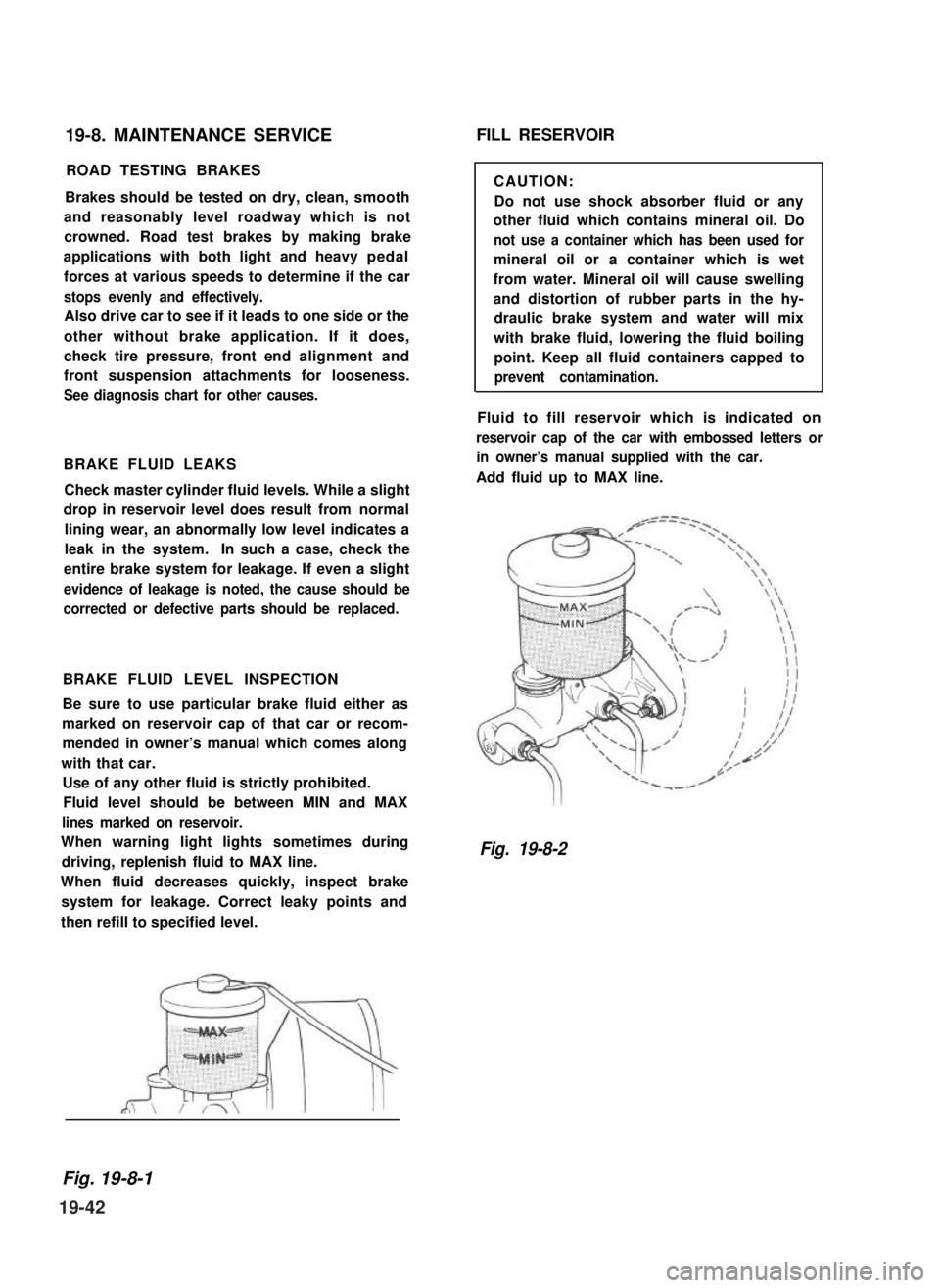
Fluid level should be between MIN and MAX
lines marked on reservoir.
When warning light lights sometimes during
driving, replenish fluid to MAX line.
When fluid decreases quickly, inspect brake
system for leakage. Correct leaky points and
then refill to specified level.
FILL RESERVOIR
CAUTION:
Do not use shock absorber fluid or any
other fluid which contains mineral oil. Do
not use a container which has been used for
mineral oil or a container which is wet
from water. Mineral oil will cause swelling
and distortion of rubber parts in the hy-
draulic brake system and water will mix
with brake fluid, lowering the fluid boiling
point. Keep all fluid containers capped to
prevent contamination.
Fluid to fill reservoir which is indicated on
reservoir cap of the car with embossed letters or
in owner’s manual supplied with the car.
Add fluid up to MAX line.
Fig. 19-8-2
Fig. 19-8-1
19-42
Page 446 of 962
Door Lock Stricker
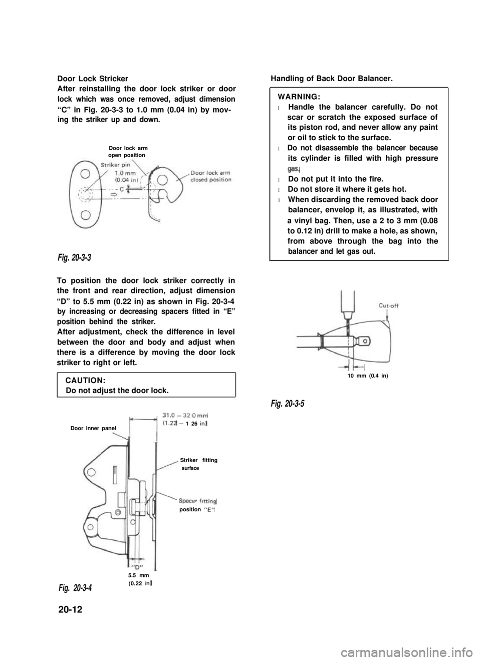
After reinstalling the door lock striker or door
lock which was once removed, adjust dimension
“C” in Fig. 20-3-3 to 1.0 mm (0.04 in) by mov-
ing the striker up and down.
Door lock armopen position
Fig. 20-3-3
To position the door lock striker correctly in
the front and rear direction, adjust dimension
“D” to 5.5 mm (0.22 in) as shown in Fig. 20-3-4
by increasing or decreasing spacers fitted in “E”
position behind the striker.
After adjustment, check the difference in level
between the door and body and adjust when
there is a difference by moving the door lock
striker to right or left.
CAUTION:
Do not adjust the door lock.
t---l
31.0-320mm
Door inner panel(1.22 - 1 26 in)
Striker fitting
/ surface
’ Spacer fitting
position “E”
Handling of Back Door Balancer.
WARNING:
l Handle the balancer carefully. Do not
scar or scratch the exposed surface of
its piston rod, and never allow any paint
or oil to stick to the surface.
l Do not disassemble the balancer because
its cylinder is filled with high pressure
Qas.
l Do not put it into the fire.
l Do not store it where it gets hot.
l When discarding the removed back door
balancer, envelop it, as illustrated, with
a vinyl bag. Then, use a 2 to 3 mm (0.08
to 0.12 in) drill to make a hole, as shown,
from above through the bag into the
balancer and let gas out.
It-10 mm (0.4 in)
Fig. 20-3-5
5.5 mm
(0.22 in)Fig. 20-3-4
20-12
Page 448 of 962
21-1.COMBINATION METER..................................
21-2.HEAD LIGHT..........................................
21-3.TURN SIGNAL LIGHT AND HAZARD WARNING LIGHT.......
21-4.WINDSHIELD WIPER MOTOR.............................
21-5.WATER TEMPERATURE METER AND GAUGE...............
21-6.FUEL LEVEL METER AND GAUGE........................
21-7.BRAKE WARNING LAMP ...............................
21-8.OIL PRESSURE LAMP..................................
4 WHEEL DRIVE LAMP.................................
21-10. SEAT BELT WARNING LAMP/BUZZER.....................
...................
...~I-I
.....
21-14. .............................................
21-15. WIRING HARNESS ROUTING............................
21-16. WIRING DIAGRAM....................................
SECTION 21
BODY ELECTRICAL EQUIPMENT
CONTENTS
21-9.
21-11. MAIN SWITCH KEY WARNING BUZZER
21-12. ILUMINATION CONTROLLER..............................................
21-13. REAR DEFOGGER ( hard-top )......................................
FUSE BOX
21-2
21-4
21-7
21-9
21-11
21-12
21-13
21-14
21-15
21-15
21-16
21-16
21-16
21-18
21-19
21-22
21-1
Page 450 of 962
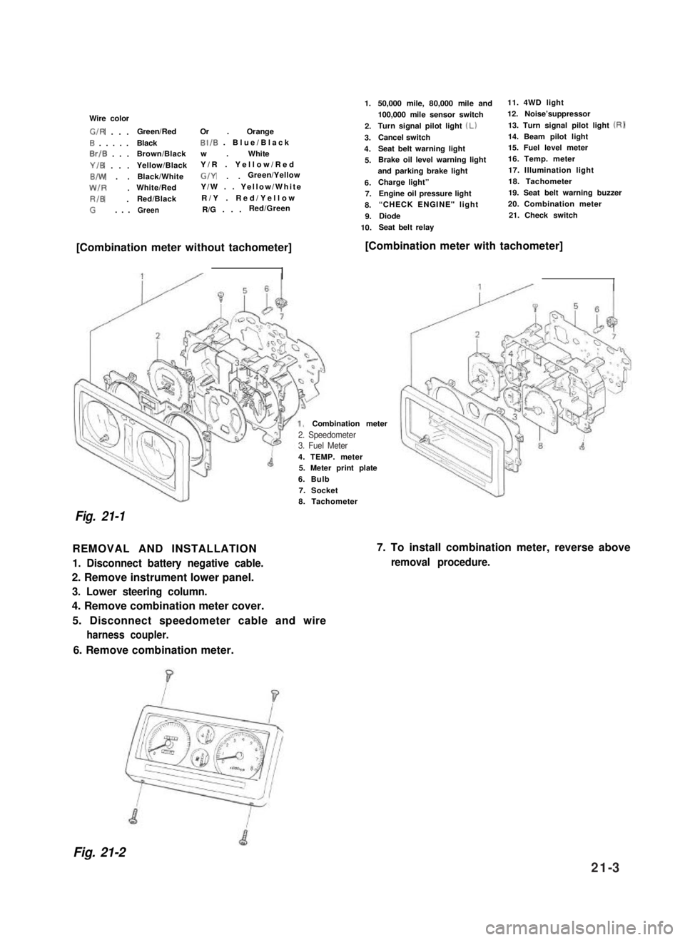
Wire color
G/R . . .Green/RedOr . Orange
0 . . . . .BlackBI/B . Blue/Black
0rlB . . .Brown/Blackw . White
Y/B . . .Yellow/BlackY/R . Yellow/Red
B/W . .Black/WhiteG/Y . .Green/Yellow
W/R .White/RedY/W . . Yellow/White
RIB .Red/BlackR/Y . Red/Yellow
G. . .GreenR/G . . .Red/Green
1.
2.
3.
4.
5.
6.7.
8.
9.
10.
50,000 mile, 80,000 mile and11. 4WD light
100,000 mile sensor switch12. Noise’suppressor
Turn signal pilot light (Lb13. Turn signal pilot light (RI
Cancel switch14. Beam pilot light
Seat belt warning light15. Fuel level meter
Brake oil level warning light16. Temp. meter
and parking brake light17. Illumination light
Charge light”18. Tachometer
Engine oil pressure light19. Seat belt warning buzzer
“CHECK ENGINE" light 20. Combination meter
Diode21. Check switch
Seat belt relay
[Combination meter without tachometer][Combination meter with tachometer]
4. TEMP. meter5. Meter print plate
6. Bulb
7. Socket
Combination meter
Fig. 21-1
8. Tachometer
REMOVAL AND INSTALLATION
1. Disconnect battery negative cable.
2. Remove instrument lower panel.
3. Lower steering column.
4. Remove combination meter cover.
5. Disconnect speedometer cable and wire
harness coupler.
7. To install combination meter, reverse above
removal procedure.
6. Remove combination meter.
Fig. 21-2
2. Speedometer3. Fuel Meter
21-3
Page 454 of 962
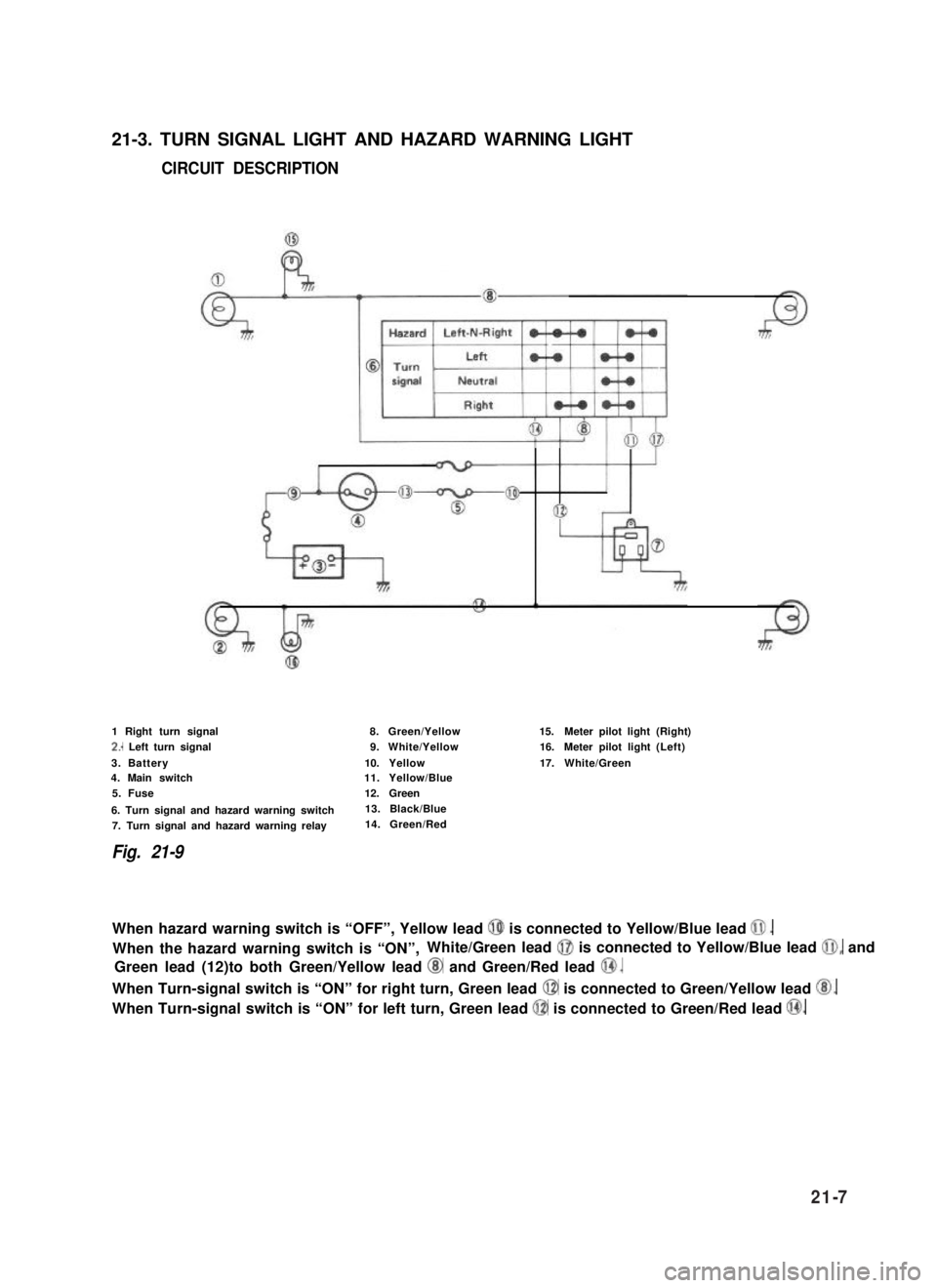
21-3. TURN SIGNAL LIGHT AND HAZARD WARNING LIGHT
CIRCUIT DESCRIPTION
1 Right turn signal
2.. Left turn signal
3. Battery4. Main switch
5. Fuse
6. Turn signal and hazard warning switch
7. Turn signal and hazard warning relay
Fig. 21-9
8.Green/Yellow
9.White/Yellow
10.Yellow11.Yellow/Blue
12.Green
13. Black/Blue
14. Green/Red
15.Meter pilot light(Right)
16.Meter pilot light(Left)
17.White/Green
When hazard warning switch is “OFF”, Yellow lead @ is connected to Yellow/Blue lead 0.
When the hazard warning switch is “ON”,White/Green lead @I is connected to Yellow/Blue lead @I, and
Green lead (12)to both Green/Yellow lead @ and Green/Red lead @.
When Turn-signal switch is “ON” for right turn, Green lead @ is connected to Green/Yellow lead @.
When Turn-signal switch is “ON” for left turn, Green lead @ is connected to Green/Red lead @.
21-7
Page 455 of 962
INSPECTION
1) Trouble diagnosis
Symptom
1. Lights will not come on in either left or
right group of light.
2. Hazard light comes on but turn signal
lights will not.
3. No light comes on; or lights light up but
do not flicker.
4. Turn signal lights are satisfactory, but
hazard light will not come on.
5. Flickering freueqncy is erratic, or lights
remain lit.
6. Turning on hazard warning switch lights up
only one group of lights.
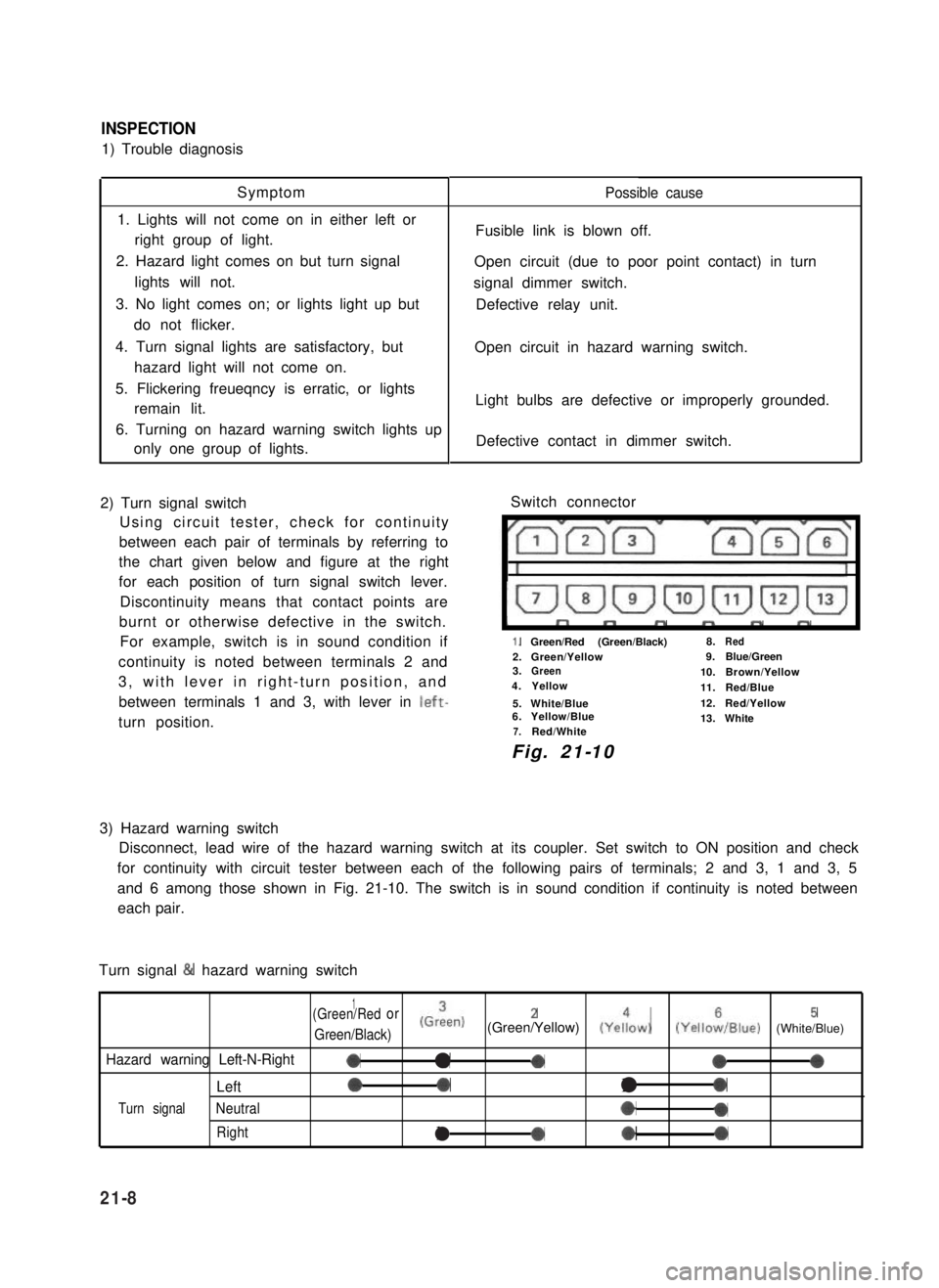
2) Turn signal switch
Using circuit tester, check for continuity
between each pair of terminals by referring to
the chart given below and figure at the right
for each position of turn signal switch lever.
Discontinuity means that contact points are
burnt or otherwise defective in the switch.
For example, switch is in sound condition if
continuity is noted between terminals 2 and
3, with lever in right-turn position, and
between terminals 1 and 3, with lever in left-
turn position.
Possible cause
Fusible link is blown off.
Open circuit (due to poor point contact) in turn
signal dimmer switch.
Defective relay unit.
Open circuit in hazard warning switch.
Light bulbs are defective or improperly grounded.
Defective contact in dimmer switch.
Switch connector
I”””yrm-
1.Green/Red (Green/Black)8.Red
2.Green/Yellow9.Blue/Green3.Green10.Brown/Yellow4.Yellow11.Red/Blue
5.White/Blue12.Red/Yellow6.Yellow/Blue13.White7.Red/White
Fig. 21-10
3) Hazard warning switch
Disconnect, lead wire of the hazard warning switch at its coupler. Set switch to ON position and check
for continuity with circuit tester between each of the following pairs of terminals; 2 and 3, 1 and 3, 5
and 6 among those shown in Fig. 21-10. The switch is in sound condition if continuity is noted between
each pair.
Turn signal & hazard warning switch
1(Green/Redor
Green/Black)
(Grien)2(Green/Yellow) (Yeiow)5(YelloiIBlue) (White/Blue)
Hazard warning Left-N-Right0a-000
Left00l0
Turn signalNeutral*0
Rightla*0
21-8
Page 460 of 962
![SUZUKI GRAND VITARA 1987 Service Repair Manual [Gauge unit]21-7. BRAKE WARNING LAMP
Use ohmmeter to confirm that level gauge unit
changes in resistance with change of the float
position. Float position-to-resistance relation-
ship can be plotted i SUZUKI GRAND VITARA 1987 Service Repair Manual [Gauge unit]21-7. BRAKE WARNING LAMP
Use ohmmeter to confirm that level gauge unit
changes in resistance with change of the float
position. Float position-to-resistance relation-
ship can be plotted i](/manual-img/20/57437/w960_57437-459.png)
[Gauge unit]21-7. BRAKE WARNING LAMP
Use ohmmeter to confirm that level gauge unit
changes in resistance with change of the float
position. Float position-to-resistance relation-
ship can be plotted in a graph as shown below.
The brake warning lamp system consists of the
brake fluid level switch installed to the master
cylinder reservoir and the lamp inside the
combination meter.
This circuit includes a parking brake switch
which gives a warning for unreleased parking
brake.
F-E
Fig. 21-20 Resistance-Fuel Level Relationship
Fig. 21-21
F : Full
E : Empty
OPERATION
Brake fluid level warning lamp circuit consists of
brake fluid level switch installed in master
cylinder reservoir, brake fluid level warning lamp
in gage cluster and check relay.
Also, this circuit is additionally provided with
parking brake switch which warns that parking
brake is applied.when engine is stopped,
warning lamp comes on, if ignition switch is
turned ON and parking brake is applied.
For bulb check, warning lamp comes on briefly
during engine starting regardless of brake fluid
level position and parking brake operation.
Because point of check relay is closed.
After engine is started, release parking brake.
If lamp gose off, brake fluid level is adequate.
When warning lamp dose not operate, use circuit
diagram as reference to check bulb, wiring, etc.
r---i
check relayl-2-l
B/Y : Black/Yellow1. Fluid level switch
R/B : Red/Black2. Warning lamp
B: Black3. Parking brake switch
B/W : Black/White4. Main switch
B/BI : Black/Blue5. Battery
Fig. 27-22
21-13