Page 1127 of 1865
TROUBLESHOOTING 7C
76G07C-020
76G07C-021
76G07C-022
4. Vacuum Leakage
Check for vacuum leakage.
(1) Disconnect the vacuum hose to the vacuum
diaphragm.
(2) Connect a vacuum pump to the hose.
(3) Apply vacuum and check if vacuum leaks.
(4) If vacuum leaks, check the vacuum hose and
vacuum diaphragm. Replace if necessary.
5. Idle Speed and Ignition Timing
Check idle speed and ignition timing. (Refer to Sec-
tion 4A.)
6. Tire Inflation Pressure
Check tire inflation pressure. (Refer to page 12—2.)
7. Inhibitor Switch
Check the inhibitor switch for operation. (Refer to
page 7C—23.)
76G07C-023
7C-13
Page 1137 of 1865

ELECTRIC COMPONENTS 7C
76G07C-036
76G07C-037
76G07C-038
ELECTRIC COMPONENTS
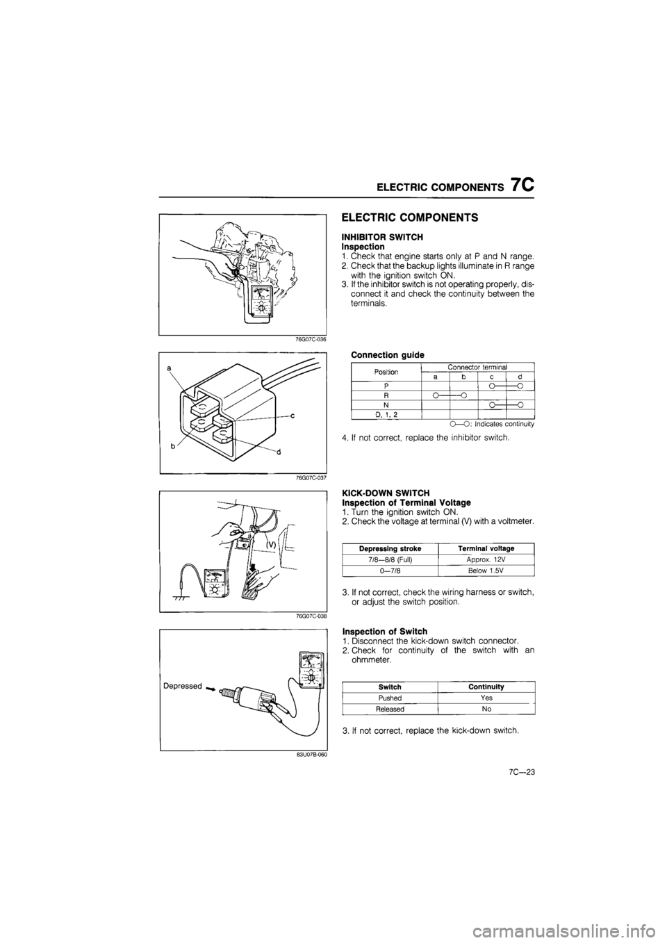
INHIBITOR SWITCH
Inspection
1. Check that engine starts only at P and N range.
2. Check that the backup lights illuminate in R range
with the ignition switch ON.
3. If the inhibitor switch is not operating properly, dis-
connect it and check the continuity between the
terminals.
Connection guide
Position
N
D, 1, 2
Connector terminal
-O
O -O
-O
O—O: Indicates continuity
4. If not correct, replace the inhibitor switch.
KICK-DOWN SWITCH
Inspection of Terminal Voltage
1. Turn the ignition switch ON.
2. Check the voltage at terminal (V) with a voltmeter.
Depressing stroke Terminal voltage
7/8-8/8 (Full) Approx. 12 V
0-7/8 Below 1,5V
3. If not correct, check the wiring harness or switch,
or adjust the switch position.
Inspection of Switch
1. Disconnect the kick-down switch connector.
2. Check for continuity of the switch with an
ohmmeter.
Switch Continuity
Pushed Yes
Released No
3. If not correct, replace the kick-down switch.
83U07B-060
7C—23
Page 1310 of 1865
1 0 STEERING WHEEL AND COLUMN
REMOVAL
1. Remove the horn cap.
2. Remove the locknut.
76G10X-007
3. The steering wheel must be removed with a suita-
ble puller.
Caution
Be careful not to subject the steering shaft to
severe impact in the axial direction when
removing or installing the steering wheel.
76G10X-008
4. Remove the column cover.
5. Disconnect the ignition switch connector.
6. Remove the combination switch.
76G10X-009
7. Remove the lower panel and switch panel.
8. Remove the duct.
76G10X-010
10-22
Page 1376 of 1865

1 0 ELECTRICAL COMPONENTS OF ELECTRONICALLY-CONTROLLED POWER STEERING (ECPS)
76G10X-020
76G10X-021
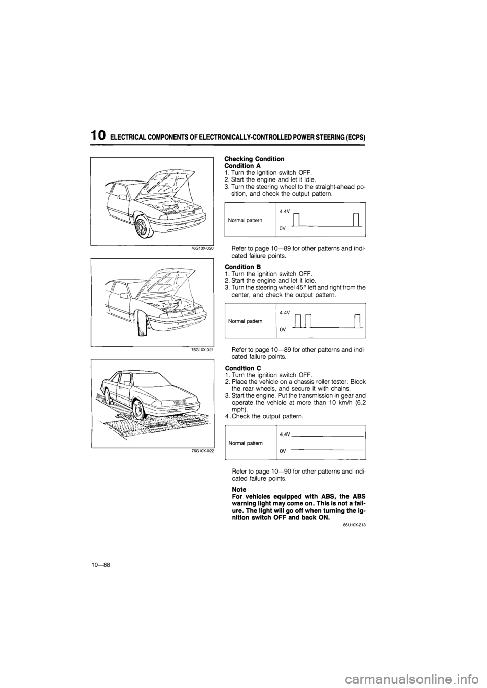
Checking Condition
Condition A
1. Turn the ignition switch OFF.
2. Start the engine and let it idle.
3. Turn the steering wheel to the straight-ahead po-
sition, and check the output pattern.
Refer to page 10—89 for other patterns and indi-
cated failure points.
Condition B
1. Turn the ignition switch OFF.
2. Start the engine and let it idle.
3. Turn the steering wheel 45° left and right from the
center, and check the output pattern.
Refer to page 10—89 for other patterns and indi-
cated failure points.
Condition C
1. Turn the ignition switch OFF.
2. Place the vehicle on a chassis roller tester. Block
the rear wheels, and secure it with chains.
3. Start the engine. Put the transmission in gear and
operate the vehicle at more than 10 km/h (6.2
mph).
4.Check the output pattern.
76G10X-022
Normal pattern
4 4V
Normal pattern Normal pattern
uV
Refer to page 10—90 for other patterns and indi-
cated failure points.
Note
For vehicles equipped with ABS, the ABS
warning light may come on. This is not a fail-
ure. The light will go off when turning the ig-
nition switch OFF and back ON.
86U10X-213
10—88
Page 1377 of 1865

ELECTRICAL COMPONENTS OF ELECTRONICALLY-CONTROLLED POWER STEERING (ECPS) 1 0
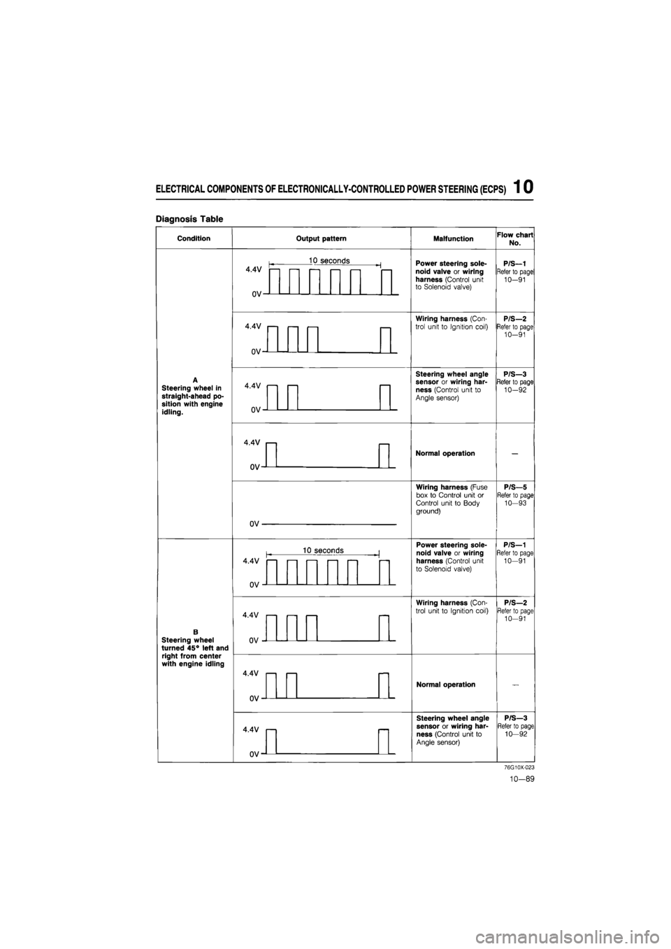
Diagnosis Table
Condition Output pattern Malfunction Flow chart
No.
4.4V
0V-
10 seconds Power steering sole-noid valve or wiring harness (Control unit to Solenoid valve)
P/S—1
Refer to page
10-91
4.4V
0V-
Wiring harness (Con-
trol unit to Ignition coil) P/S—2 Refer to page 10-91
Steering wheel in straight-ahead po-sition with engine idling.
4.4V
OV-
Steering wheel angle sensor or wiring har-ness (Control unit to Angle sensor)
P/S—3 Refer to page 10-92
4.4V
ov-
Normal operation
Wiring harness (Fuse box to Control unit or Control unit to Body ground)
P/S—5 Refer to page 10—93
OV
10 seconds Power steering sole-
noid valve or wiring
harness (Control unit
to Solenoid valve)
P/S—1 Refer to page 10—91
B Steering wheel turned 45° left and right from center with engine idling
4.4V
0V
Wiring harness (Con-
trol unit to Ignition coil)
P/S—2 Refer to page 10-91
4.4V
0V'
Normal operation
4.4V
0V-
Steering wheel angle
sensor or wiring har-
ness (Control unit to
Angle sensor)
P/S—3 Refer to page 10—92
76G10X-023
10-89
Page 1378 of 1865

1 0 ELECTRICAL COMPONENTS OF ELECTRONICALLY-CONTROLLED POWER STEERING (ECPS)
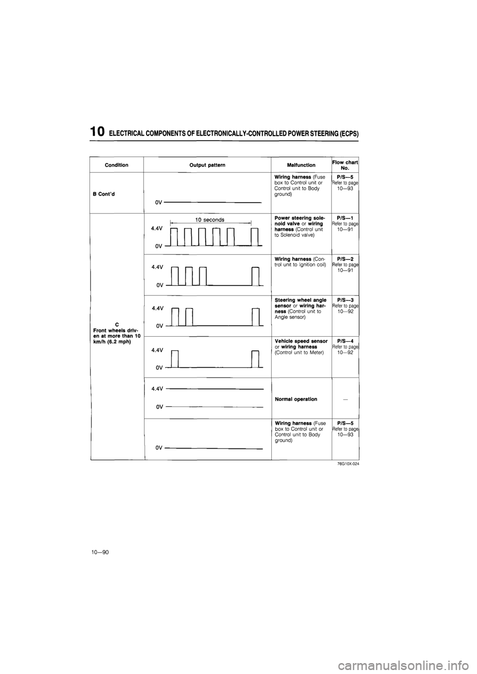
Condition Output pattern Malfunction Flow chart No.
B Cont'd
OV
Wiring harness (Fuse
box to Control unit or
Control unit to Body
ground)
P/S—5 Refer to page 10-93
C
Front wheels driv-en at more than 10 km/h (6.2 mph)
4.4V —
1 3 s econds Power steering sole-noid valve or wiring harness (Control unit to Solenoid valve)
P/S—1 Refer to page 10-91
C
Front wheels driv-en at more than 10 km/h (6.2 mph)
uv
Power steering sole-noid valve or wiring harness (Control unit to Solenoid valve)
P/S—1 Refer to page 10-91
C
Front wheels driv-en at more than 10 km/h (6.2 mph)
4.4V
n\i
—
Wiring harness (Con-trol unit to Ignition coil) P/S—2 Refer to page 10-91
C
Front wheels driv-en at more than 10 km/h (6.2 mph)
Wiring harness (Con-trol unit to Ignition coil) P/S—2 Refer to page 10-91
C
Front wheels driv-en at more than 10 km/h (6.2 mph)
4.4V
Steering wheel angle sensor or wiring har-ness (Control unit to Angle sensor)
P/S-3 Refer to page 10—92
C
Front wheels driv-en at more than 10 km/h (6.2 mph)
V
Steering wheel angle sensor or wiring har-ness (Control unit to Angle sensor)
P/S-3 Refer to page 10—92
C
Front wheels driv-en at more than 10 km/h (6.2 mph)
4.4V
Vehicle speed sensor or wiring harness
(Control unit to Meter)
P/S—4 Refer to page 10-92
C
Front wheels driv-en at more than 10 km/h (6.2 mph)
uv
Vehicle speed sensor or wiring harness
(Control unit to Meter)
P/S—4 Refer to page 10-92
C
Front wheels driv-en at more than 10 km/h (6.2 mph)
4.4V
OV —
Normal operation —
C
Front wheels driv-en at more than 10 km/h (6.2 mph)
OV
Wiring harness (Fuse box to Control unit or Control unit to Body ground)
P/S—5 Refer to page 10-93
76G10X-024
10-90
Page 1379 of 1865
ELECTRICAL COMPONENTS
OF
ELECTRONICALLY-CONTROLLED POWER STEERING (ECPS) 1 0
Flow Chart
P/S—1
Failure of solenoid valve or wiring harness (Control unit to Solenoid valve)
Disconnect control unit connector. Check resistance between terminals.
Check voltage between (YL) and D (B) terminal of
control unit connector with engine running
OK
Terminal Resistance
M(LB)—N(LG) 3.5 — 7Q
Check control unit connector, solenoid valve connec-tor, and joint connector for connection, and check output pattern again.
NG
Check the solenoid valve (Refer to page 10—93),
NG
Replace solenoid valve.
P/S-Z Broken wiring harness
(Control unit to Coil)
Terminate of control unit connector with engine running.
NG
Replace control unit.
OK Repair wiring harness (Control unit to Solenoid valve).
Terminal Voltage
L(YL)-D(B) Approx. 12V
NG Repair the wiring harness (Control unit to Ignition
coil).
OK
Replace control unit.
76G10X-025
10—91
Page 1381 of 1865
ELECTRICAL COMPONENTS OF ELECTRONICALLY-CONTROLLED POWER STEERING (ECPS) 1 0
Broken wiring harness (Fuse box
P/S—5 to Control unit, Control unit or to Body ground)
Measure voltage between terminal of control unit
connector and body ground with ignition ON.
Terminal Voltage UK Replace the control unit.
E(BG) Approx. 12V
D(B) Approx. OV
NG
Replace METER 10A fuse or repair wiring harnesses (Fuse box to Control unit or Control unit to Body ground).
86U10X-218
86U10X-219
Power Steering Solenoid Valve
Inspection
1. Listen for actuation sound of the solenoid valve
when applying 12V between A and B terminals.
2. If no sound is heard, check the resistance of the
solenoid valve with an ohmmeter.
Terminals Resistance
A — B 3.4—6.9 Q
3.
If
there is no continuity, replace the solenoid valve.
Steering Angle Sensor
Inspection
Refer to page 15—16.
Vehicle Speed Sensor
Inspection
Refer to page 15—88.
76G10X-044
10-93