1987 MAZDA 626 ignition
[x] Cancel search: ignitionPage 1473 of 1865
ANTI-LOCK BRAKE SYSTEM (ABS) 1 1
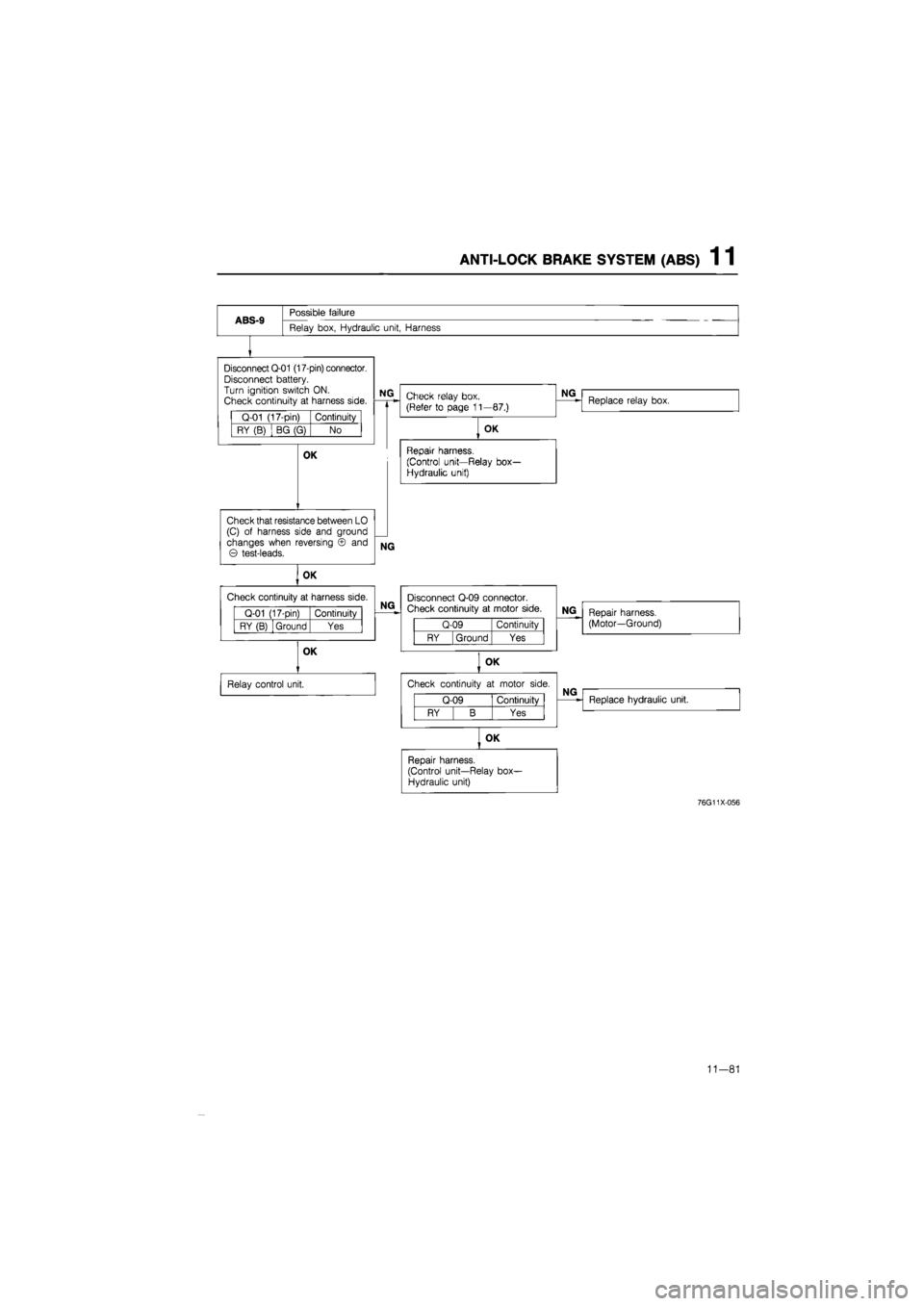
ABS-9
Possible failure
Relay box, Hydraulic unit, Harness
Disconnect Q-01 (17-pin) connector. Disconnect battery. Turn ignition switch
ON.
Check continuity
at
harness side.
Q-01 (17-pin) Continuity
RY (B) BG (G) No
NG
OK
Check that resistance between
LO
(C)
of
harness side
and
ground changes when reversing
© and
© test-leads.
NG
Check relay box. (Refer
to
page 11—87.)
OK
Repair harness.
(Control unit—Relay box-Hydraulic unit)
NG
Replace relay box.
OK
Check continuity
at
harness side.
Q-01 (17-pin) Continuity
RY (B) Ground Yes
OK
Relay control unit.
NG
Disconnect Q-09 connector. Check continuity
at
motor side.
Q-09 Continuity
RY Ground Yes
NG
Repair harness. (Motor—Ground)
OK
Check continuity
at
motor side.
Q-09 Continuity
RY B Yes
NG
Replace hydraulic unit.
OK
Repair harness. (Control unit—Relay box-Hydraulic unit)
76G11X-056
11-81
Page 1475 of 1865
ANTI-LOCK BRAKE SYSTEM (ABS) 1 1
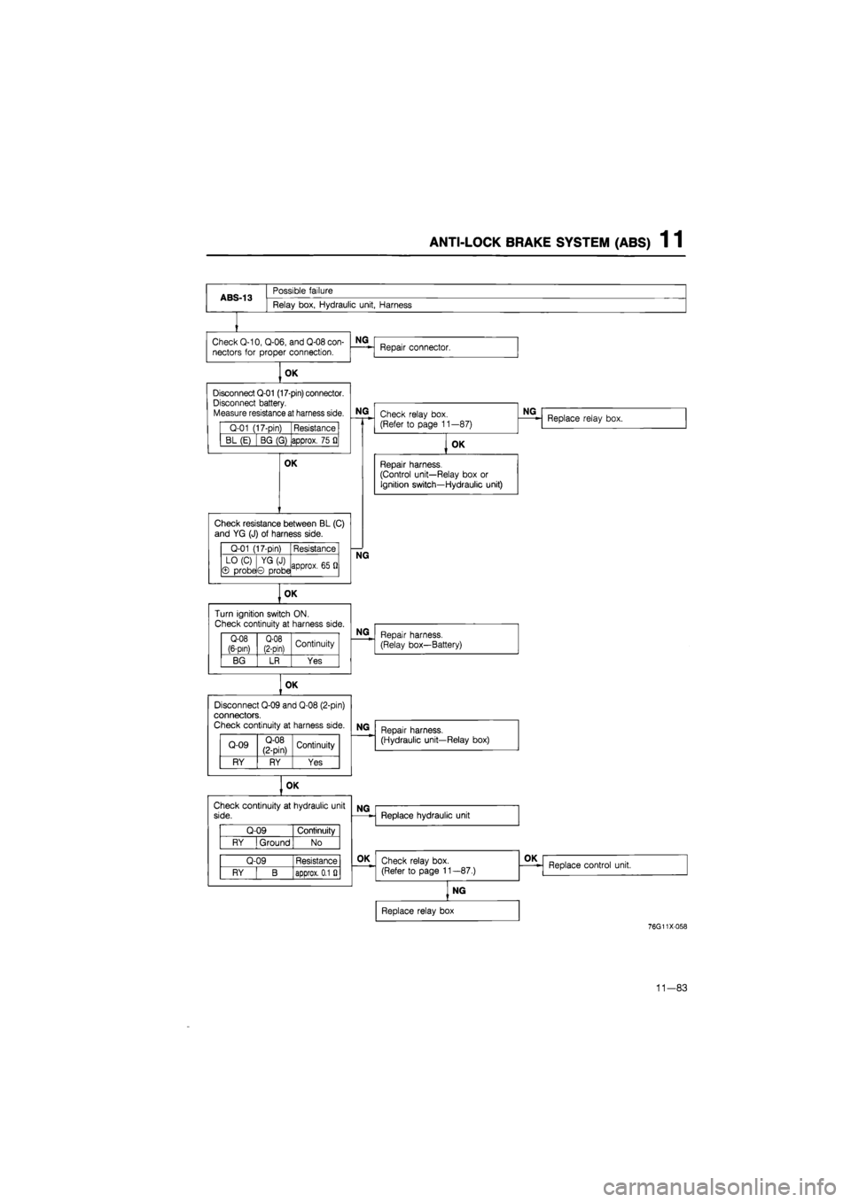
ABS-13
Possible failure
Relay box, Hydraulic unit, Harness
Check Q-10, Q-06, and Q-08 con-
nectors
for
proper connection.
OK
Q-01 (17-pin) Resistance
BL (E) BG (G) approx. 75
Q
OK
Q-01 (17-pin) Resistance
LO (C) © probe YG(J) © probe approx.
65 Q
Q-08 (6-pin) Q-08 (2-Din) Continuity
BG LR Yes
OK
Disconnect Q-09 and Q-08 (2-pin) connectors. Check continuity
at
harness side.
Q-09 Q-08 (2-pin) Continuity
RY RY Yes
Q-09 Continuity
RY I Ground No
Q-09 Resistance
RY B approx. 0.1
Si
NG
Disconnect Q-01 (17-pin) connector. Disconnect battery. Measure resistance at harness side.
NG
Check resistance between BL (C)
and
YG
(J)
of
harness side.
OK
Check continuity
at
hydraulic unit side.
NG
OK
Turn ignition switch ON.
Check continuity
at
harness side.
Repair connector.
Check relay box. (Refer
to
page 11 —87)
NG
Replace relay box.
OK
Repair harness.
(Control unit—Relay box
or
Ignition switch—Hydraulic unit)
NG
Repair harness. (Relay box—Battery)
NG
Repair harness. (Hydraulic unit—Relay box)
NG
OK
Replace hydraulic unit
Check relay box. (Refer
to
page 11—87.)
OK
Replace control unit.
NG
Replace relay box
76G11X-058
11-83
Page 1478 of 1865
1 1 ANTI-LOCK BRAKE SYSTEM (ABS)
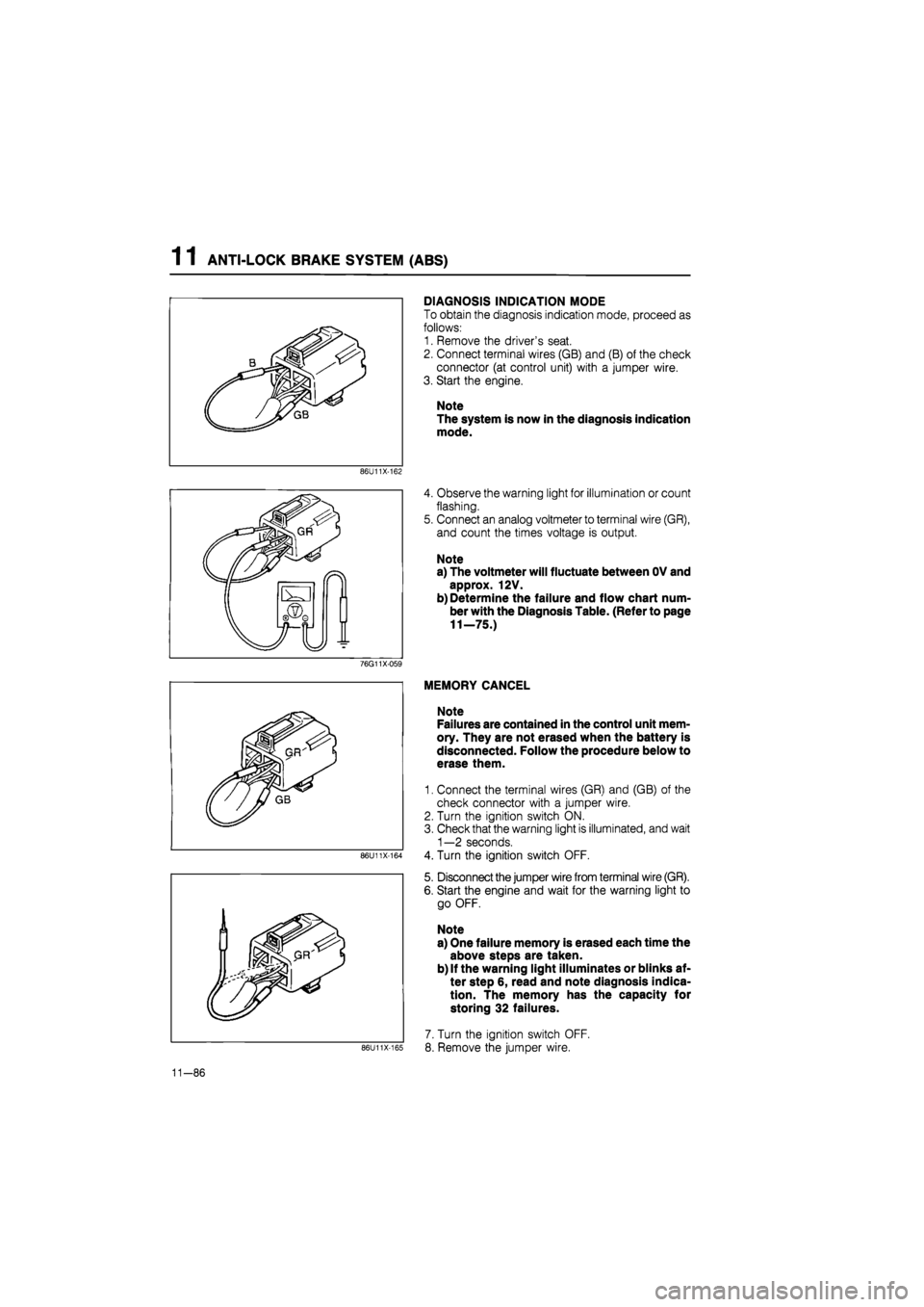
DIAGNOSIS INDICATION MODE
To obtain the diagnosis indication mode, proceed as
follows:
1. Remove the driver's seat.
2. Connect terminal wires (GB) and (B) of the check
connector (at control unit) with a jumper wire.
3. Start the engine.
Note
The system is now in the diagnosis indication
mode.
86U11X-162
4. Observe the warning light for illumination or count
flashing.
5. Connect an analog voltmeter to terminal wire (GR),
and count the times voltage is output.
Note
a) The voltmeter will fluctuate between OV and
approx. 12V.
b) Determine the failure and flow chart num-
ber with the Diagnosis Table. (Refer to page
11—75.)
76G11X-059
86U11X-164
86U11X-165
MEMORY CANCEL
Note
Failures are contained in the control unit mem-
ory. They are not erased when the battery is
disconnected. Follow the procedure below to
erase them.
1. Connect the terminal wires (GR) and (GB) of the
check connector with a jumper wire.
2. Turn the ignition switch ON.
3. Check that the warning light is illuminated, and wait
1—2 seconds.
4. Turn the ignition switch OFF.
5. Disconnect the jumper wire from terminal wire (GR).
6. Start the engine and wait for the warning light to
go OFF.
Note
a) One failure memory is erased each time the
above steps are taken.
b) If the warning light illuminates or blinks af-
ter step 6, read and note diagnosis indica-
tion. The memory has the capacity for
storing 32 failures.
7. Turn the ignition switch OFF.
8. Remove the jumper wire.
11-86
Page 1479 of 1865
ANTI-LOCK BRAKE SYSTEM (ABS) 1 1
86U11X-1C
Q-08
Q-08
Fail-safe relay
B B BG
(Q-08)(Q-09)
V
BL BR
Motor relay
B BR (Q-09)
LO RY
View from male-pin side
86U11X-167
76G11X-096
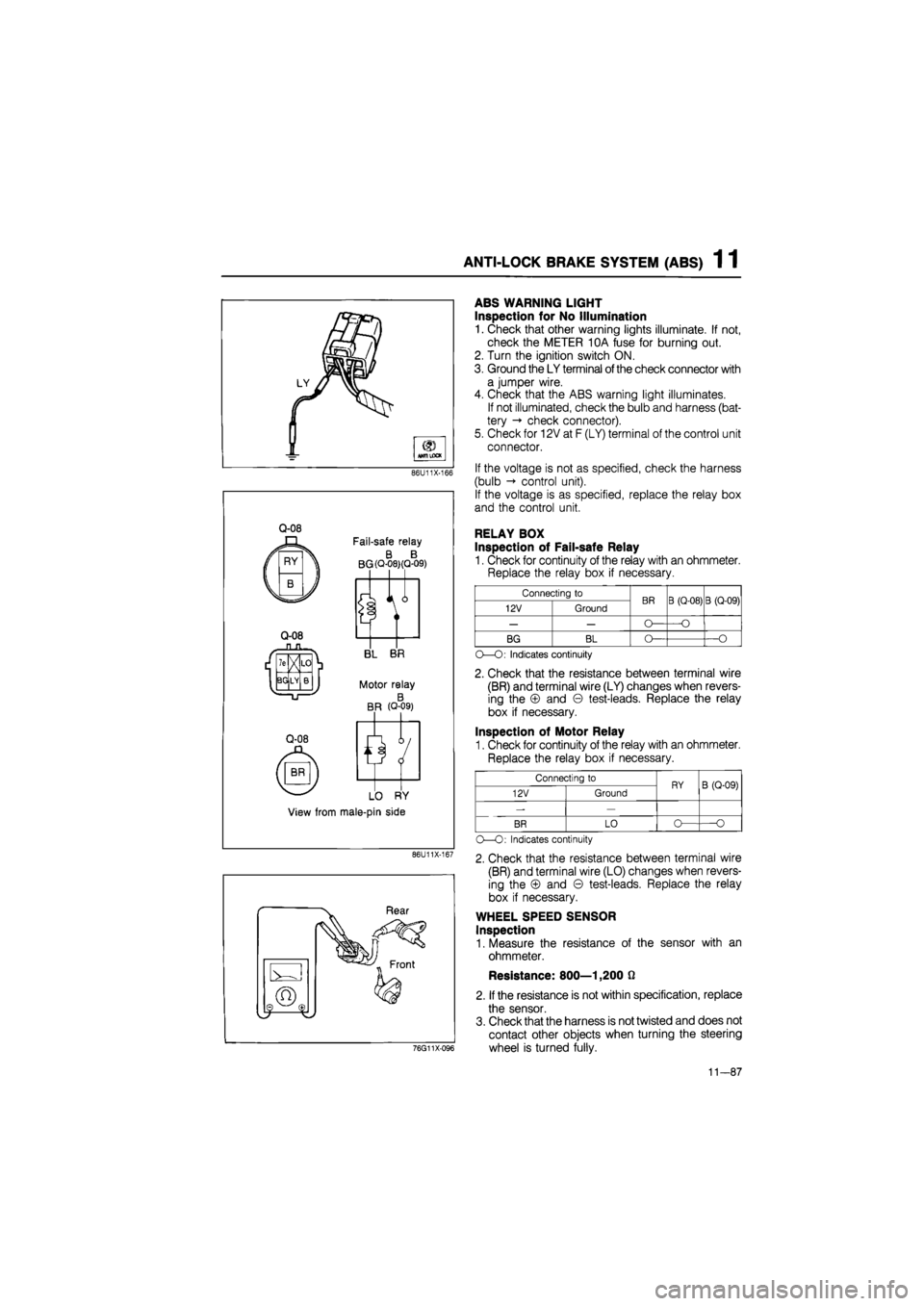
ABS WARNING LIGHT
Inspection for No Illumination
1. Check that other warning lights illuminate. If not,
check the METER 10A fuse for burning out.
2. Turn the ignition switch ON.
3. Ground the LY terminal
of
the check connector with
a jumper wire.
4. Check that the ABS warning light illuminates.
If not illuminated, check the bulb and harness (bat-
tery -» check connector).
5. Check for 12V at F (LY) terminal of the control unit
connector.
If the voltage is not as specified, check the harness
(bulb control unit).
If the voltage is as specified, replace the relay box
and the control unit.
RELAY BOX
Inspection of Fail-safe Relay
1. Check for continuity of the relay with an ohmmeter.
Replace the relay box if necessary.
Connecting to BR B (Q-08) B (Q-09) 12V Ground BR B (Q-08) B (Q-09)
— — O— —O
BG BL O— —O
O—O: Indicates continuity
2. Check that the resistance between terminal wire
(BR) and terminal wire (LY) changes when revers-
ing the © and © test-leads. Replace the relay
box if necessary.
Inspection of Motor Relay
1. Check for continuity of the relay with an ohmmeter.
Replace the relay box if necessary.
Connecting to RY B (Q-09) 12V Ground RY B (Q-09)
-—
BR LO o— O
O—O: Indicates continuity
2. Check that the resistance between terminal wire
(BR) and terminal wire (LO) changes when revers-
ing the © and © test-leads. Replace the relay
box if necessary.
WHEEL SPEED SENSOR
Inspection
1. Measure the resistance of the sensor with an
ohmmeter.
Resistance: 800—1,200 0
2. If the resistance is not within specification, replace
the sensor.
3. Check that the harness is not twisted and does not
contact other objects when turning the steering
wheel is turned fully.
11-87
Page 1487 of 1865
ANTI-LOCK BRAKE SYSTEM (ABS) 1 1
86U11X-190
86U11X-191
76G11X098
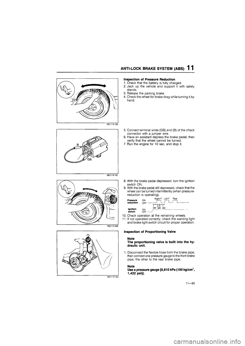
Inspection of Pressure Reduction
1. Check that the battery is fully charged.
2. Jack up the vehicle and support it with safety
stands.
3. Release the parking brake.
4. Check the wheel for brake drag while turning it by
hand.
5. Connect terminal wires (GB) and (B) of the check
connector with a jumper wire.
6. Have an assistant depress the brake pedal; then
verify that the wheel cannot be turned.
7. Run the engine for 10 sec, and stop it.
8. With the brake pedal depressed, turn the ignition
switch ON.
9. With the brake pedal still depressed, check that the
wheel can be turned intermittently (when pressure-
reduction is operating).
Right'F Left F Rear Pressure reduction
Ignition switch ON OFF
1 05 1 sec sec sec
J
10. Check operation at the remaining wheels.
11. If not operated correctly, check the warning light
and brake light switch circuit for proper operation.
Inspection of Proportioning Valve
Note
The proportioning valve is built into the hy-
draulic unit.
1. Disconnect the flexible hose from the brake pipe;
then connect one pressure gauge to the front brake
pipe, the other to the rear brake pipe.
Note
Use a pressure gauge [9,810 kPa (100 kg/cm2,
1,422 psi)].
86U11X-193
11—95
Page 1510 of 1865
FRONT SHOCK ABSORBER AND SPRING 1 3
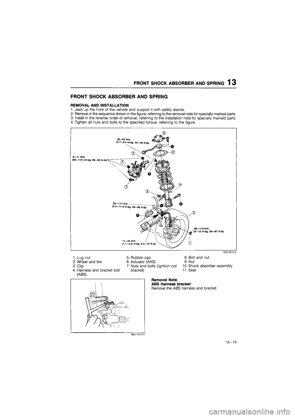
FRONT SHOCK ABSORBER AND SPRING
REMOVAL AND INSTALLATION
1. Jack up the front of the vehicle and support it with safety stands.
2. Remove in the sequence shown in the figure, referring to the removal note for specially marked parts.
3. Install in the reverse order of removal, referring to the installation note for specially marked parts.
4. Tighten all nuts and bolts to the specified torque, referring to the figure.
.CD
46—63 N m (4.7—6.4 m-kg, 34—46 ft-lb)
8—11 Nm (80—110 cm-kg, 69—95 In-lb)
93-117 N-m . (9.5-11.9 m-kg, 69—86 ft-lb)
88—118 N-m (9—12 m-kg, 65—87 ft-lb)
11—25 N-m (1.1—2.6 m-kg, 8.0—19 ft-lb)
1. Lug nut
2. Wheel and tire
3. Clip
4. Harness and bracket bolt
(ABS)
5. Rubber cap
6. Actuator (AAS)
7. Nuts and bolts (Ignition coil
bracket)
76G13X-012
8. Bolt and nut
9. Nut
10. Shock absorber assembly
11. Seat
86U13X-010
Removal Note
ABS Harness bracket
Remove the ABS harness and bracket.
13—13
Page 1656 of 1865
15
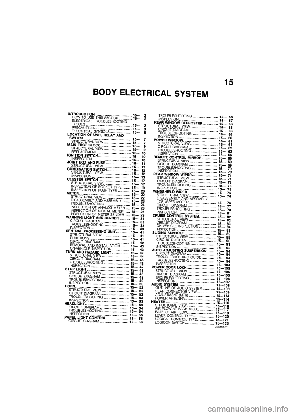
BODY ELECTRICAL SYSTEM
INTRODUCTION 15- 2 HOW TO USE THIS SECTION 15— 2 ELECTRICAL TROUBLESHOOTING TOOLS 15- 2 PRECAUTION 15— 3 ELECTRICAL SYMBOLS 15- 6 LOCATION OF UNIT, RELAY AND SWITCH 15- 7
STRUCTURAL VIEW 15— 7 MAIN FUSE BLOCK 15- 9 STRUCTURAL VIEW 15— 9 REPLACEMENT 15—10 IGNITION SWITCH 15—10
INSPECTION 15— 10 JOINT BOX AND FUSE 15—11
STRUCTURAL VIEW 15—11
COMBINATION SWITCH 15-12 STRUCTURAL VIEW 15- 12 INSPECTION 15— 13 CLUSTER SWITCH 15—17 STRUCTURAL VIEW 15— 17 INSPECTION OF ROCKER TYPE 15— 19
INSPECTION OF PUSH TYPE 15— 20 METER 15— 22 STRUCTURAL VIEW 15— 22 DISASSEMBLY AND ASSEMBLY 15— 23
TROUBLESHOOTING 15— 24 INSPECTION OF ANALOG METER .... 15— 26 INSPECTION OF DIGITAL METER 15— 27
INSPECTION OF METER SENDER 15— 29 WARNING LIGHT AND SENDER 15- 31 CIRCUIT DIAGRAM 15— 31
TROUBLESHOOTING 15- 32 INSPECTION 15— 39 CENTRAL PROCESSING UNIT 15— 41 STRUCTURAL VIEW 15— 41 FUNCTIONS 15- 41 CIRCUIT DIAGRAM 15— 42 REMOVAL AND INSTALLATION 15— 43
ON-VEHICLE INSPECTION 15- 43 TURN AND HAZARD LIGHT 15- 44 STRUCTURAL VIEW 15— 44 CIRCUIT DIAGRAM 15— 45
TROUBLESHOOTING 15- 46 INSPECTION 15— 47 STOP LIGHT 15— 48
STRUCTURAL VIEW 15— 48 CIRCUIT DIAGRAM 15— 49
TROUBLESHOOTING 15- 49 INSPECTION 15- 50 HORN 15— 52 STRUCTURAL VIEW 15— 52 CIRCUIT DIAGRAM 15— 52 TROUBLESHOOTING 15— 53 INSPECTION 15-53 HEADLIGHT 15— 54 CIRCUIT DIAGRAM 15— 54 TROUBLESHOOTING 15— 54 INSPECTION 15— 55 PANEL LIGHT CONTROL 15— 56 CIRCUIT DIAGRAM 15— 56
TROUBLESHOOTING 15_ 5fi INSPECTION 17 REAR WINDOW DEFROSTER ..i".'! 15- 58
STRUCTURAL VIEW 15-5fl CIRCUIT DIAGRAM 15_ «
TROUBLESHOOTING '.. 15_ 59
INSPECTION
15-60 POWER WINDOW 15-61 STRUCTURAL VIEW il_ «1 CIRCUIT DIAGRAM 15_ 62 TROUBLESHOOTING 15- «3 INSPECTION 15-66 REMOTE CONTROL MIRROR ........15- 69 STRUCTURAL VIEW 15-69 CIRCUIT DIAGRAM 15_ 69
TROUBLESHOOTING 15_ 70 INSPECTION 15_ 70 REAR WINDOW WIPER 15_ 71 STRUCTURAL VIEW 15-71 CIRCUIT DIAGRAM .'.'.'...' 15_ 72
TROUBLESHOOTING 15-73 INSPECTION 15-75 WINDSHIELD WIPER 15-76 STRUCTURAL VIEW ' ' 15— 7e
DISASSEMBLY AND ASSEMBLY OF WIPER MOTOR 15_ 76 CIRCUIT DIAGRAM 15-77 TROUBLESHOOTING " " 15— 70 INSPECTION 15-81 CRUISE CONTROL SYSTEM 15- 82 STRUCTURAL VIEW 15-82 CIRCUIT DIAGRAM 15-83 ON-VEHICLE INSPECTION \..\m 15- 84 INSPECTION 15-87 SLIDING SUNROOF 15-89 STRUCTURAL VIEW 15_ 89 CIRCUIT DIAGRAM i5_ 90
TROUBLESHOOTING 15— 91 INSPECTION 15_ 90 AUTO ADJUSTING SUSPENSION 15— 94
CIRCUIT DIAGRAM 15- 94
TROUBLESHOOTING GUIDE 15— 94
TROUBLESHOOTING 15— 94
INSPECTION 15-104
POWER DOOR LOCK 15-105
STRUCTURAL VIEW 15-105
CIRCUIT DIAGRAM 15-105
TROUBLESHOOTING 15-106 INSPECTION 15-107 AUDIO SYSTEM " 15_108 OUTLINE OF AUDIO SYSTEM 15-108 REAR CONNECTOR VIEW 15-109 ADJUSTMENT (MTR) 15—114 POWER ANTENNA 15-114 HEATER J
STRUCTURAL VIEW 15-116 AIR FLOW AT EACH MODE 15-117 RATE OF AIR FLOW 15-119 LEVER CONTROL TYPE 15-120 LOGICAL CONTROL
TYPE
15—121 LOGICON SWITCH 15—123
76G15X-001
Page 1660 of 1865
INTRODUCTION 15
69G15X-006
4BG15X-003
69G15X-007
/Wire
Shield braid wire
Insulation
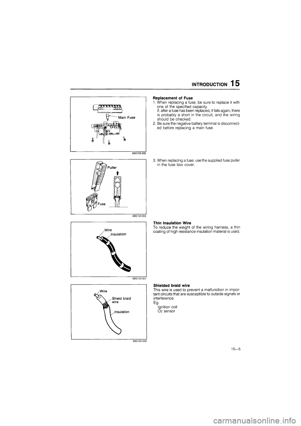
Replacement of Fuse
1. When replacing a fuse, be sure to replace it with
one of the specified capacity.
If, after a fuse has been replaced, it fails again, there
is probably a short in the circuit, and the wiring
should be checked.
2. Be sure the negative battery terminal is disconnect-
ed before replacing a main fuse.
3. When replacing a fuse, use the supplied fuse puller
in the fuse box cover.
Thin Insulation Wire
To reduce the weight of the wiring harness, a thin
coating of high resistance insulation material is used.
Shielded braid wire
This wire is used to prevent a malfunction in impor-
tant circuits that are susceptible to outside signals or
interference.
Eg.
Ignition coil
02 sensor
69G15X-008
15—5