Page 1720 of 1865
POWER WINDOW 1 5
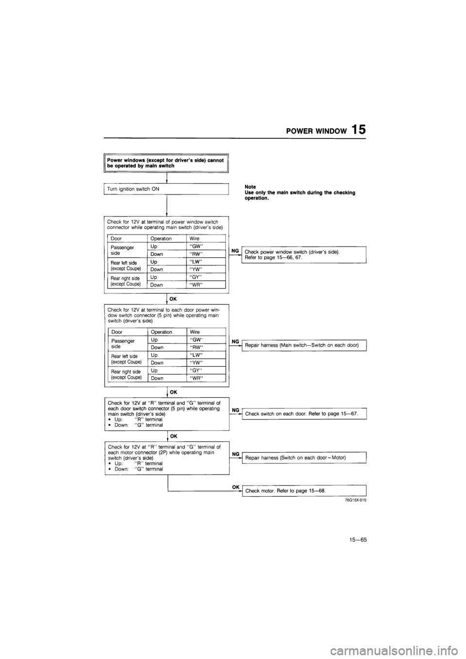
Power windows (except for driver's side) cannot be operated by main switch
Turn ignition switch
ON Note
Use only the main switch during the checking operation.
Check
for
12V
at
terminal
of
power window switch connector while operating main switch (driver's side)
Door Operation Wire
Passenger
side
Up "GW" Passenger
side Down "RW"
Rear left side
(except Coupe)
Up "LW" Rear left side
(except Coupe) Down "YW"
Rear right side
(except Coupe)
Up "GY" Rear right side
(except Coupe) Down "WR"
NG
Check power window switch (driver's side). Refer
to
page 15—66,
67.
OK
Check
for
12V
at
terminal
to
each door power win-dow switch connector
(5
pin) while operating main switch (driver's side)
Door Operation Wire
Passenger Up "GW"
side Down "RW"
Rear left side Up "LW"
(except Coupe) Down "YW"
Rear right side Up "GY"
(except Coupe) Down "WR"
Repair harness (Main switch—Switch
on
each door)
OK
Check
for
12V
at
"R" terminal and
"G"
terminal
of
each door switch connector
(5
pin) while operating main switch (driver's side)
•
Up: "R"
terminal
• Down:
"G"
terminal
NG
Check
for
12V
at
"R" terminal and
"G"
terminal
of
each door switch connector
(5
pin) while operating main switch (driver's side)
•
Up: "R"
terminal
• Down:
"G"
terminal
NG
Check switch
on
each door. Refer
to
page 15—67.
Check
for
12V
at
"R" terminal and
"G"
terminal
of
each door switch connector
(5
pin) while operating main switch (driver's side)
•
Up: "R"
terminal
• Down:
"G"
terminal
OK
76G15X-015
15—65
Page 1725 of 1865
15 REMOTE CONTROL MIRROR
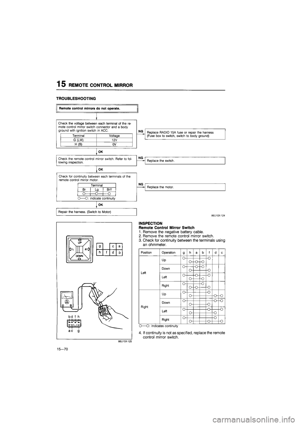
TROUBLESHOOTING
Terminal Voltage
G (LW) 12V
H(B) OV
OK
Check the remote control mirror switch. Refer
to
fol-lowing inspection.
OK
Check for continuity between each terminals
of
the remote control mirror motor.
Terminal
Br
O
Lg
-O-
BrY
-O
O—O: indicate continuity
Remote control mirrors do not operate.
Check the voltage between each terminal
of
the
re-
mote control mirror switch connector and
a
body ground with ignition switch
in
ACC.
NG
Replace RADIO 15A fuse
or
repair the harness (Fuse box
to
switch, switch
to
body ground)
NG
Replace the switch.
NG
Replace the motor.
OK
Repair the harness. (Switch
to
Motor)
86U15X-124
86U15X-125
INSPECTION
Remote Control Mirror Switch
1. Remove the negative battery cable.
2. Remove the remote control mirror switch.
3. Check for continuity between the terminals using
an ohmmeter.
Position
Left
Right
Operation
Up
Down
Left
Right
Up
Down
Left
Right
9
O
o-
o
o
o
o-
o-
o
O-O—o
o-
o-
o~o
o
o-
o
o-
o-o
•o -o
•o
f
•o
-o
-O
o
-o
-o
o
o
o-o
-o-o
-o
o
•o
o
O—O: Indicates continuity
4. If continuity is not as specified, replace the remote
control mirror switch.
15—70
Page 1739 of 1865
1 5 CRUISE CONTROL SYSTEM
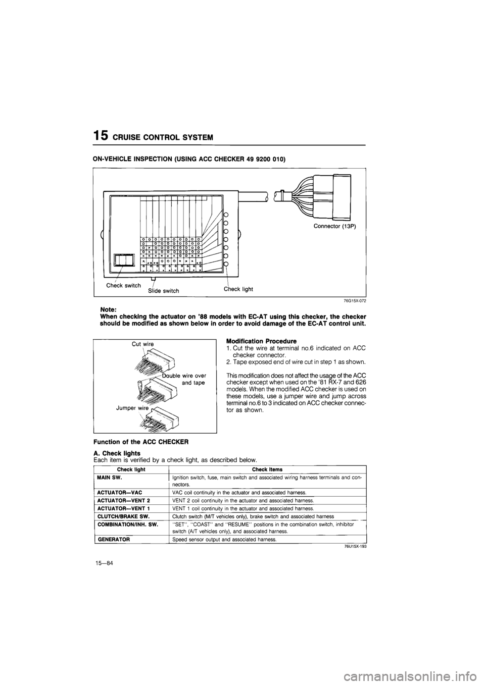
ON-VEHICLE INSPECTION (USING ACC CHECKER 49 9200 010)
76G15X-072
Note:
When checking the actuator on '88 models with EC-AT using this checker, the checker
should be modified as shown below in order to avoid damage of the EC-AT control unit.
Modification Procedure
1. Cut the wire at terminal no.6 indicated on ACC
checker connector.
2. Tape exposed end of wire cut in step 1 as shown.
This modification does not affect the usage of the ACC
checker except when used on the '81 RX-7 and 626
models. When the modified ACC checker is used on
these models, use a jumper wire and jump across
terminal no.6 to 3 indicated on ACC checker connec-
tor as shown.
Function of the ACC CHECKER
A. Check lights
Each item is verified by a check light, as described below.
Check light Check items
MAIN SW.
Ignition switch, fuse, main switch and associated wiring harness terminals and con-
nectors.
ACTUATOR—VAC
VAC coil continuity
in
the actuator and associated harness.
ACTUATOR—VENT 2
VENT
2
coil continuity
in
the actuator and associated harness.
ACTUATOR—VENT 1
VENT
1
coil continuity
in
the actuator and associated harness.
CLUTCH/BRAKE SW.
Clutch switch (M/T vehicles only), brake switch and associated harness
COMBINATION/INH. SW.
"SET", "COAST" and "RESUME" positions
in
the combination switch, inhibitor
switch (A/T vehicles only), and associated harness.
GENERATOR
Speed sensor output and associated harness.
76U15X-193
15-84
Page 1740 of 1865
CRUISE CONTROL SYSTEM 1 5
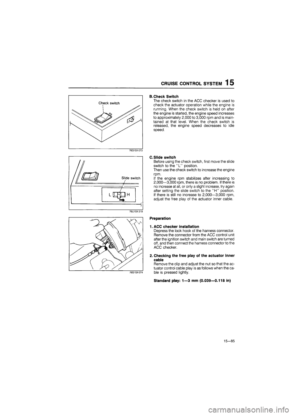
B.Check Switch
The check switch in the ACC checker is used to
check the actuator operation while the engine is
running. When the check switch is held on after
the engine is started, the engine speed increases
to approximately 2,000 to 3,000 rpm and is main-
tained at that level. When the check switch is
released, the engine speed decreases to idle
speed.
76G15X-073
C.Slide switch
Before using the check switch, first move the slide
switch to the "L" position.
Then use the check switch to increase the engine
rpm.
If the engine rpm stabilizes after increasing to
2,000—3,000 rpm, there is no problem. If there is
no increase at all, or only a slight increase, try again
after setting the slide switch to the "H" position.
If there is still no increase to 2,000—3,000 rpm,
adjust the free play of the actuator inner cable.
76U15X-319
76G15X-074
Preparation
1. ACC checker installation
Depress the lock hook of the harness connector.
Remove the connector from the ACC control unit
after the ignition switch and main switch are turned
off, and then connect the harness connector to the
ACC checker.
2. Checking the free play of the actuator inner
cable
Remove the clip and adjust the nut so that the ac-
tuator control cable play is as follows when the ca-
ble is pressed lightly.
Standard play: 1—3 mm (0.039—0.118 in)
15—85
Page 1741 of 1865
1
5
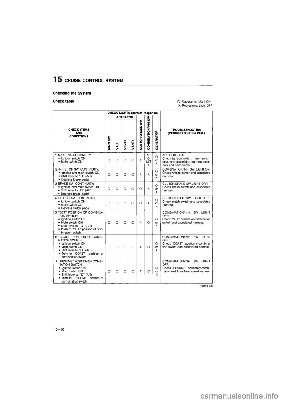
CRUISE CONTROL SYSTEM
Checking
the
System
Check table O:
Represents: Light ON
X: Represents: Light OFF
CHECK LIGHTS (correct response)
ACTUATOR 5
CHECK ITEMS AND CONDITIONS
MAIN
SW
VAC
i
VENT2 VANT1
i
'
CLUTCH/BRAKE
SW
CONBINATION/INH
S
'
GENERATOR
TROUBLESHOOTING (INCORRECT RESPONSE)
1. MAIN SW. CONTINUITY:
• Ignition switch
ON
• Main switch
ON O O O o
X
A/T
O
M/T X
O
or X
ALL LIGHTS OFF: Check ignition switch, main switch, fuse, and associated harness termi-nals and connectors
2. INHIBITOR SW. CONTINUITY:
• Ignition and main switch ON. • Shift lever
to "D"
(A/T)
• Depress brake pedal
o o o o
X X
0
or X
COMBINATION/INH. SW. LIGHT ON:
Check inhibitor switch and associated
harness.
3. BRAKE SW. CONTINUITY: • Ignition and main switch
ON
• Shift lever
to
"D"
(A/T)
• Depress brake pedal
o o o o 0
X
o
or X
CLUTCH/BRAKE SW.LIGHT OFF:
Check brake switch and associated
harness.
4. CLUTCH SW. CONTINUITY:
• Ignition switch
ON
• Main switch
ON
• Depress clutch pedal
o o o 0 o
X
O
or X
CLUTCH/BRAKE SW. LIGHT OFF: Check clutch switch and associated harness.
5. "SET" POSITION
OF
COMBINA-TION SWITCH:
• Ignition switch
ON
• Main switch
ON
• Shift lever
to "D"
(A/T) • Push
to
"SET" position
of
com-bination switch
o o o o
X
o
O
or X
COMBINATION/INH.
SW.
LIGHT OFF: Check "SET" position of combination switch and associated harness.
6. "COAST" POSITION
OF
COMBI-NATION SWITCH • Ignition switch
ON
• Main switch
ON
• Shift lever
to "D"
(A/T) • Turn
to
"COAST" position
of
combination switch
o o o o
X
o
O
or X
COMBINATION/INH.
SW.
LIGHT OFF: Check "COAST" position in combina-tion switch and associated harness.
7. "RESUME" POSITION OF COMBI-NATION SWITCH
• Ignition switch
ON
• Main switch
ON
• Shift lever
to "D"
(A/T)
• Turn
to
"RESUME" position
of
combination switch
o o o o
X
o O
or X
COMBINATION/INH.
SW.
LIGHT OFF: Check "RESUME" position of combi-nation switch and associated harness.
76U15X-198
15—86
Page 1746 of 1865
SLIDING SUNROOF 1 5
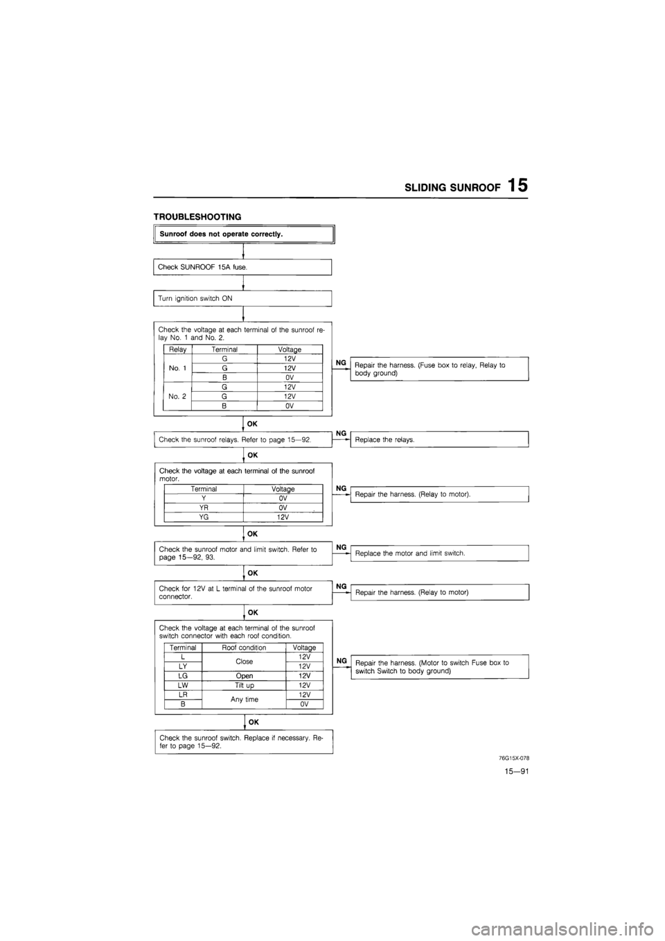
TROUBLESHOOTING
Sunroof does not operate correctly.
Check SUNROOF 15A fuse.
Turn ignition switch
ON
Check the voltage
at
each terminal
of
the sunroof
re-
lay No.
1
and No.
2.
Relay Terminal Voltage
No.
1
G 12V
No.
1
G 12V No.
1
B OV
No.
2
G 12V
No.
2
G 12V No.
2
B OV
OK
Check the sunroof relays. Refer
to
page 15—92.
OK
Check the voltage
at
each terminal
of
the sunroof motor.
OK
Check the sunroof motor and limit switch. Refer
to
page 15—92,
93.
OK
Check
for
12V
at L
terminal
of
the sunroof motor connector.
OK
Check the voltage
at
each terminal
of
the sunroof switch connector with each roof condition.
OK
Terminal Voltage
Y OV
YR OV
YG 12V
Terminal Roof condition Voltaae
L Close 12V
LY Close 12V
LG Open 12V
LW Tilt
up
12V
LR Any time 12V
B Any time OV
Check the sunroof switch. Replace
if
necessary.
Re-
fer
to
page 15—92.
NG
Repair the harness. (Fuse box
to
relay, Relay
to
body ground)
NG
Replace the relays.
NG
Repair the harness. (Relay
to
motor).
NG
Replace the motor and limit switch.
NG
Repair the harness. (Relay
to
motor)
NG
Repair the harness. (Motor
to
switch Fuse box
to
switch Switch
to
body ground)
76G15X-078
15—91
Page 1750 of 1865
AUTO ADJUSTING SUSPENSION (AAS) 1 5
Checking Condition
Note:
Turn the ignition switch OFF to reset the con-
trol unit before each test.
Condition A
1. Turn the ignition switch ON.
2. Set steering wheel in the straight-ahead position,
and check the output pattern.
86U15X-154
Condition B
1. Turn the ignition switch ON.
2. Turn the steering wheel right and left, and check
the output pattern.
86U15X-155
•
/
AUTO ADJUSTING SUSPENSION I- AUTO—i SOFT NORMAL SPORT
Condition C
1. Turn the ignition switch ON.
2. Change the AAS switch from NORMAL to SPORT
or from SPORT to NORMAL, and check the out-
put pattern.
86U15X-156
Condition D
1. Operate the vehicle on a chassis roller.
2. Check the output pattern at above 15 km/h (9.3
mph).
Caution
a) Block the rear wheels.
b) In vehicle equipped with ABS, ABS warn-
ing light may come on, which is not a fail-
ure. The light goes off by turning ignition
switch OFF and again ON.
86U15X-157
15—95
Page 1754 of 1865
AUTO ADJUSTING SUSPENSION
(AAS) 1 5
AAS-3
Normal operation
or
failure
of
the wir-ing harness (Fuse box
to
Control unit, Control unit
to
Body ground)
Check the voltage between each terminal
of
the con-trol unit connector and
a
body ground with ignition ON.
Terminal Voltage
G(B) OV
J(B) OV
K (BY) Approx.
12V
OK
Normal operation.
NG
Replace TURN 15A fuse
or
repair the wiring harness (Fuse box
to
Control unit, Control unit
to
Body ground.)
86U15X-161
AAS-4
Failure
of
wiring harnesses (Fuse
box
to Control unit, Control unit
to
Body
ground).
Check the voltage between each terminal
of
control unit connector and
a
body ground with ignition
ON.
Terminals Voltage
G (B) OV
J (B) OV
K (BY)
ADDTOX.
12V
OK
Replace the control unit.
NG
Replace TURN 15A fuse
or
repair the wiring harness-
es (Fuse box
to
Control unit, Control unit
to
Body
ground.)
86U15X-162
15-99