1987 MAZDA 626 brake light
[x] Cancel search: brake lightPage 14 of 1865

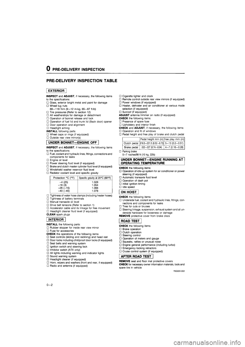
0 PRE-DELIVERY INSPECTION
PRE-DELIVERY INSPECTION TABLE
EXTERIOR
INSPECT and ADJUST, if necessary, the following items
to the specifications:
• Glass, exterior bright metal and paint for damage
• Wheel lug nuts
88—118 N m (9—12 m-kg, 65—87 ft-lb)
• Tire pressures (Refer to section 12)
• All weatherstrips for damage or detachment
• Operation of bonnet release and lock
• Operation of fuel lid and trunk lid (Back door) opener
• Door operation and alignment
• Headlight aiming
INSTALL following parts:
• Wheel caps or rings (if equipped)
• Outside rear view mirror(s)
UNDER BONNET—ENGINE OFF
INSPECT and ADJUST, if necessary, the following items
to the specifications:
• Fuel, coolant and hydraulic lines, fittings, connections and
components for leaks
• Engine oil level
• Power steering fluid level (if equipped)
• Brake and clutch master cylinder fluid level (if equipped)
• Windshield washer reservoir fluid level
• Radiator coolant level and specific gravity
Protection °C (°F) Specific gravity at 20°C (68°F)
-4 (25) 1.028
-16(3) 1.054
-26 (-15) 1.066 -40 (-40) 1.078
• Tightness of water hose clamps (including heater hoses)
• Tightness of battery terminals
• Manual transaxle oil level
• Drive belt tensions (Refer to section 1)
• Accelerator cable and its linkage for free movement
• Headlight cleaner fluid level (if equipped)
CLEAN spark plugs
INTERIOR
INSTALL the following parts:
• Rubber stopper for inside rear view mirror
• Fuse for accessories
CHECK the operations of the following items:
• Seat controls (sliding and reclining) and head rest
• Door locks including childproof door locks (if equipped)
• Seat belts and warning system
• Ignition switch and steering lock
• Inhibitor switch (ATX only)
• All lights including warning and indicator lights
• Sound warning system
• Headlight cleaner (if equipped)
• Horn, wipers and washers (front and rear, if equipped)
• Radio and antenna (if equipped)
• Cigarette lighter and clock
• Remote control outside rear view mirrors (if equipped)
• Power windows (if equipped)
• Heater, defroster and air conditioner at various mode
selection (if equipped)
• Sunroof (if equipped)
ADJUST antenna trimmer on radio (if equipped)
CHECK the following items:
• Presence of spare fuse
• Upholstery and interior finish
CHECK and ADJUST, if necessary, the following items:
• Operation and fit of windows
• Pedal height and free play of brake and clutch pedal
Pedal height mm (in) free play mm (in)
Clutch pedal 216.5-221.5 (8.52-8.72) 5-13 (0.2-0.51)
Brake pedal 222-227 (8.74-8.94) 4-7 (0.16-0.28)
• Parking brake
5-7 noches/98 N (10 kg, 22lb)
UNDER BONNET—ENGINE RUNNING AT
OPERATING TEMPERATURE
CHECK the following items:
• Operation of idle-up system for air conditioner or power
steering (if equipped)
• Automatic transaxle fluid level
• Operation of dash pot
• Initial ignition timing
• Idle speed
ON HOIST
CHECK the following items:
• Underside fuel, coolant and hydraulic lines, fittings, con-
nections and components for leaks
• Tires for cuts or bruises
• Steering linkage, suspension, exhaust system and all un-
derside hardware for looseness or damage
REMOVE protective cover from brake discs
ROAD TEST"
CHECK the following items:
• Brake operation
• Clutch operation
• Steering control
• Operation of meters and gauge
• Squeaks, rattles or unusual noise
• Engine general performance (including turbo)
• Emergency locking retractors
• Cruise control system (if equipped)
AFTER ROAD TEST
REMOVE seat and floor mat protective covers
CHECK for necessary owner information materials, tools and
spare tire in vehicle
-76G00X-002
0-2
Page 15 of 1865

For ECE Leaded gasoline
Chart symbols:
I
A
R
T
O
X
Inspect: Visual examination or functional measurement of a system's operation (performance)
Adjust : Examination resulting in adjustment or replacement
Replace or change
Tighten
Applicable
Not applicable
F8 engine with carbretor, MTX, ATX
FE engine with carbretor, MTX, ATX
FE DOHC engine with fuel injection, 4WS, MTX
RF-CX, RF-N engine with MTX
REMARKS:
Major service interval at 12 months/20,000 km (12,000 Miles), Lubrication service based on distance only 10,000 km (6,000 Miles) not time
After 80,000 km (48,000 Miles) or 48 months, continue to follow the described maintenance items and intervals periodically.
As for * marked items in this maintenance chart, please pay attention to the following points.
*1 Replacement of the timing belt is required at every 100,000 km (60,000 Miles). Failure to repace the timing belt may result in damage to the engine.
*2 If the vehicle is operatie under the following conditions, it is suggested that the engine oil and oil filter be changed more often than at usual recommended intervals.
a) Driving in dusty conditions.
b) Extended periods of idling or low speed operation.
c) Driving for a prolonged period in cold temperatures or driving only short distances regulary.
*3. If the vehicle is operated in very dusty or sandy areas, inspect and, if necessary, replace more often than at usual recommended intervals.
*4. This is a full function check of all electrical systems, i.e., all lights, washers (including condition of blades) electrical windows, sunroof, horn, etc....
*5. Replace every two years.
If there has been continuous hard driving, mountain driving, or if the brakes are used extensively or the vehicle is operated in extremely humid climates, the
brake fluid should be changed annually.
>
Z H m >
o m
H >
CD r-m
o m
m O m
(D o> Q. ® a
(Q 0) <0 o
m a
o m
c/> o x m a
Emission Control and Related Systems
The ignition and fuel systems are vitally important to the proper operation of the emissions control and related systems, as well as for efficient engine operation.
It is strongly recommended that all servicing related to these systems be done by your Authorized Mazda Dealer.
m a
m z >
z o m
G)
Page 19 of 1865

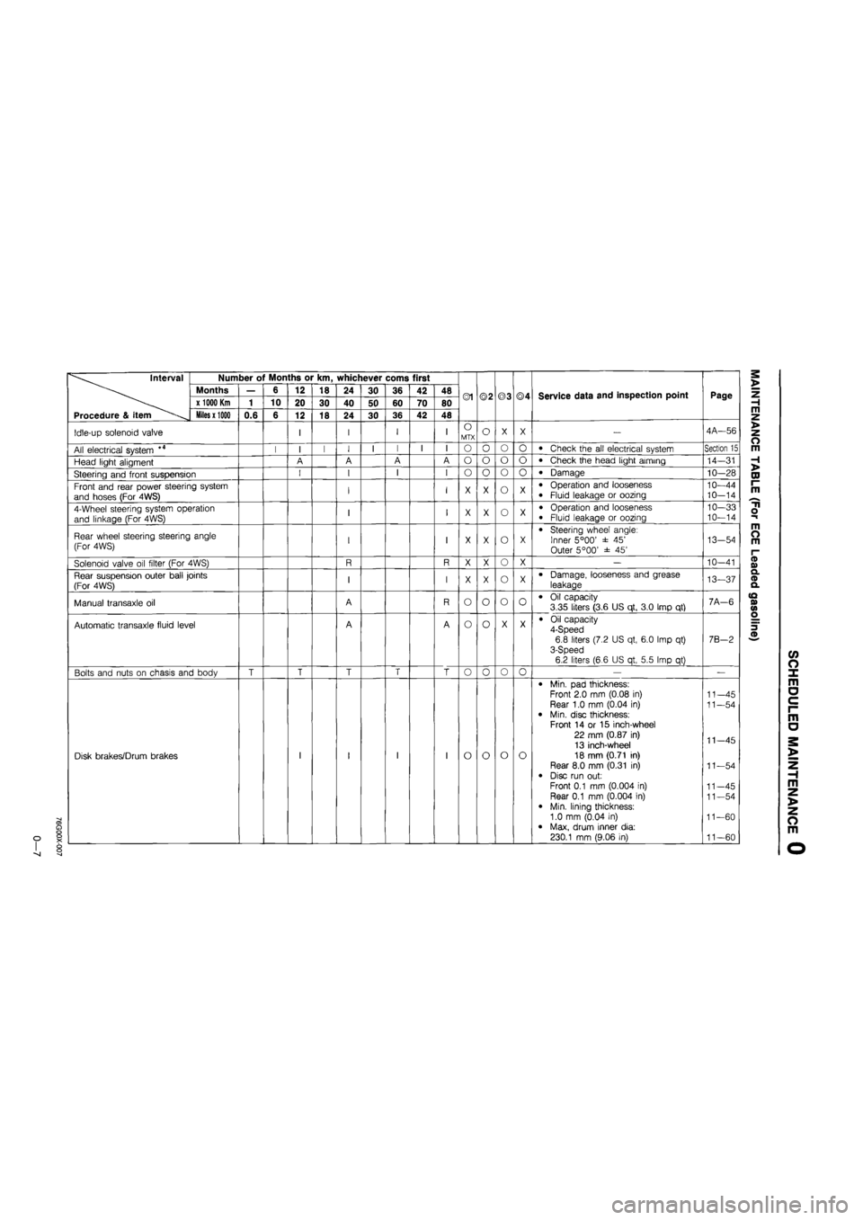
Interval
Procedure & item
Number of Months or km, whichever corns first
©1 ©2 ©3 ©4 Service data and inspection point Page
Interval
Procedure & item
Months — 6 12 18 24 30 36 42 48 ©1 ©2 ©3 ©4 Service data and inspection point Page
Interval
Procedure & item
x 1000 Km 1 10 20 30 40 50 60 70 80 ©1 ©2 ©3 ©4 Service data and inspection point Page
Interval
Procedure & item Miles x 1000 0.6 6 12 18 24 30 36 42 48
©1 ©2 ©3 ©4 Service data and inspection point Page
Idle-up solenoid valve I I I I O MTX o X X — 4A—56
All electrical system *4 I I I I I I I I o o o o • Check the all electrical system Section 15
Head light aligment A A A A o o o o • Check the head light aiming 14-31
Steering and front suspension I I I I o o o 0 • Damage 10—28
Front and rear power steering system
and hoses (For 4WS) I I X X o X • Operation and looseness • Fluid leakage or oozing 10—44 10—14
4-Wheel steering system operation
and linkage (For 4WS) I I X X o X • Operation and looseness
• Fluid leakage or oozing
10—33 10—14
Rear wheel steering steering angle
(For 4WS) I I X X o X • Steering wheel angle: Inner 5°00' ± 45' Outer 5°00' ± 45'
13-54
Solenoid valve oil filter (For 4WS) R R X X o X — 10-41
Rear suspension outer ball joints
(For 4WS) I I X X o X • Damage, looseness and grease
leakage 13—37
Manual transaxle oil A R o o o 0 • Oil capacity 3.35 liters (3.6 US qt, 3.0 Imp qt) 7A-6
Automatic transaxle fluid level A A o o X X • Oil capacity 4-Speed 6.8 liters (7.2 US qt, 6.0 Imp qt) 3-Speed 6.2 liters (6.6 US qt, 5.5 Imp qt)
7B-2
Bolts and nuts on chasis and body T T T T T o o o o — —
Disk brakes/Drum brakes I I I I o o o o
• Min. pad thickness: Front 2.0 mm (0.08 in) Rear 1.0 mm (0.04 in) • Min. disc thickness: Front 14 or 15 inch-wheel
22 mm (0.87 in) 13 inch-wheel 18 mm (0.71 in) Rear 8.0 mm (0.31 in)
• Disc run out:
Front 0.1 mm (0.004 in) Rear 0.1 mm (0.004 in)
• Min. lining thickness: 1.0 mm (0.04 in) • Max, drum inner dia: 230.1 mm (9.06 in)
11—45
11—54
11—45
11—54
11-45 11—54
11-60
11—60
Page 21 of 1865

r
For ECE Unleaded gasoline
Chart symbols:
I
A
R
T
O
X
Inspect: Visual examination or functional measurement of a system's operation (performance)
Adjust: Examination resulting in adjustment or replacement
Replace or change
Tighten
Applicable
Not applicable
FE engine with fuel injection, MTX, ATX
FE DOHC engine with fuel injection, 4WS, MTX
FE engine with carburetor, MTX, ATX
RF-CX, RF-N engine with MTX
REMARKS:
Major service interval at 12 months/20,000 km (12,000 Miles), Lubrication service based on distance only 10,000 km (6,000 Miles) not time
After 80,000 km (48,000 Miles) or 48 months, continue to follow the described maintenance items and intervals periodically.
As for * marked items in this maintenance chart, please pay attention to the following points.
*1 Replacement of the timing belt is required at every 100,000 km (60,000 Miles). Failure to repace the timing belt may result in damage to the engine.
*2 If the vehicle is operated under the following conditions, it is suggested that the engine oil and oil filter be changed more often than at usual recommended
intervals.
a) Driving in dusty conditions.
b) Extended periods of idling or low speed operation.
c) Driving for a prolonged period in cold temperatures or driving only short distances regulary.
*3. If the vehicle is operated in very dusty or sandy areas, inspect and, if necessary, replace more often than at usual recommended intervals.
*4. This is a full function check of all electrical systems, i.e., all lights, washers (including condition of blades) electrical windows, sunroof, horn, etc....
*5. Replace every two years.
If there has been continuous hard driving, mountain driving, or if the brakes are used extensively or the vehicle is operated in extremely humid climates, the brake fluid
should be changed annually.
Emission Control and Related Systems
The ignition and fuel systems are vitally important to the proper operation of the emissions control and related systems, as well as for efficient engine operation. It is
strongly recommended that all servicing related to these systems be done by your Authorized Mazda Dealer.
>
Z H m z >
o m
H >
DJ r~ m
m o m
c 3
(/> O X m o c i-m
o
m z >
z o m
CD
Page 25 of 1865

GO
Interval
Procedure & item
Number of Months or km, whichever corns first
©1 ©2 ©3 ©4 Service data and inspection point Page
Interval
Procedure & item
Months — 6 12 18 24 30 36 42 48 ©1 ©2 ©3 ©4 Service data and inspection point Page
Interval
Procedure & item
x 1000 Km 1 10 20 30 40 50 60 70 80 ©1 ©2 ©3 ©4 Service data and inspection point Page
Interval
Procedure & item Miles x 1000 0.6 6 12 18 24 30 36 42 48
©1 ©2 ©3 ©4 Service data and inspection point Page
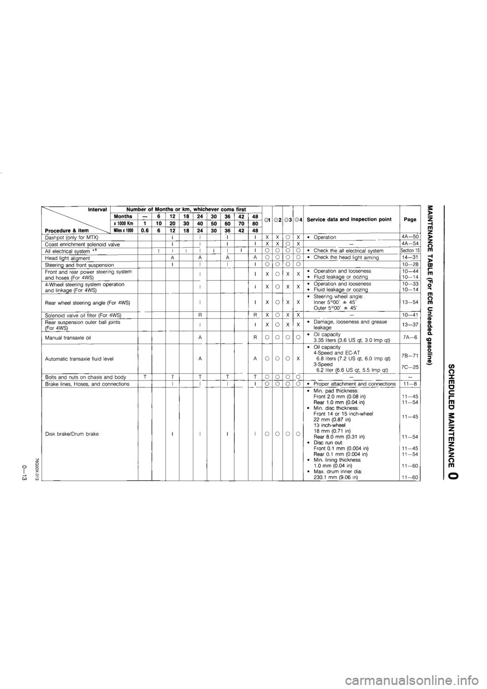
Dashpot (only for MTX) I I I I X X o X • Operation 4A—50
Coast enrichment solenoid valve I I I I X X o X — 4A—54
All electrical system *4 I I I I I I I I o o o o • Check the all electrical system Section 15
Head light aligment A A A A o o o o • Check the head light aiming 14-31
Steering and front suspension I I I I o o o o 10—28
Front and rear power steering system
and hoses (For 4WS) I I X o X X • Operation and looseness
• Fluid leakage or oozing 10—44
10-14
4-Wheel steering system operation
and linkage (For 4WS) I I X o X X • Operation and looseness
• Fluid leakage or oozing
10—33 10—14
Rear wheel steering angle (For 4WS) I I X o X X • Steering wheel angle: Inner 5°00' ± 45' Outer 5°00' ± 45'
13-54
Solenoid valve oil filter (For 4WS) R R X o X X — 10—41
Rear suspension outer ball joints
(For 4WS) I I X o X X • Damage, looseness and grease
leakage 13-37
Manual transaxle oil A R o o o o • Oil capacity 3.35 liters (3.6 US qt, 3.0 Imp qt) 7A—6
Automatic transaxle fluid level A A o o o X
• Oil capacity 4-Speed and EC-AT 6.8 liters (7.2 US qt, 6.0 Imp qt) 3-Speed 6.2 liter (6.6 US qt, 5.5 Imp qt)
7B—71
7C—25
Bolts and nuts on chasis and body T T T T T o o o o — —
Brake lines, Hoses, and connections I I I l_
I
o o o o • Proper attachment and connections 11-8
Disk brake/Drum brake I I I
l_
I o o o 0
• Min. pad thickness: Front 2.0 mm (0.08 in) Rear 1.0 mm (0.04 in)
• Min. disc thickness: Front 14 or 15 inch-wheel 22 mm (0.87 in)
13 inch-wheel 18 mm (0.71 in) Rear 8.0 mm (0.31 in)
• Disc run out:
Front 0.1 mm (0.004 in) Rear 0.1 mm (0.004 in) • Min. lining thickness: 1.0 mm (0.04 in)
• Max. drum inner dia: 230.1 mm (9.06 in)
11—45 11—54
11—45
11-54
11—45
11-54
11—60
11-60
Page 309 of 1865

INSTALLATION 1C
76G01C-227
P/S Oil Pump
1. Install the P/S oil pump.
Tightening torque:
37—52 Nm (3.8—5.3 m-kg, 27—38 ft-lb)
2. Install the P/S oil pump pully. (Refer to section 10)
Tightening torque:
55—59 Nm (5.6—6.0 m-kg, 41—43 ft-lb)
3. Set the pipe bracket in position.
Tightening torque:
8—11 Nm (80—110 cm-kg, 69—95 in-lb)
4. Install the drive belt and adjust the belt deflection.
(Refer to page 1C—7)
5. Install the drive belt cover.
Tightening torque:
8—11
N
m (80—110 cm-kg, 69—95 in-lb)
76G01C-228
Fuel Hose
Install the fuel hose.
Note
Be careful of the red marks on the hose.
76G01C-229
76G01C-230
Intercooler Pipe and Hose
1. Install the intercooler pipe and hose.
Tightening torque:
19—26 Nm (1.9—2.6 m-kg, 14—19 ft-lb)
2. Install the brake vacuum pipe.
Tightening torque:
8—11
N
m (80—110 cm-kg, 69—95 in-lb)
3. Connect the brake vacuum hose securely and
squeeze the clamp lightly with pliers to ensure a
good fit.
1C-97
Page 463 of 1865

FUEL AND EMISSION
CONTROL SYSTEMS
(FUEL INJECTION FE)
OUTLINE 4B— 2
SYSTEM DIAGRAM 4B— 2
COMPONENT LOCATION 4B— 3
VACUUM HOSE ROUTING
DIAGRAM 4B— 5
SPECIFICATIONS 4B— 6
TROUBLESHOOTING GUIDE 4B— 7
TROUBLESHOOTING
PROCEDURE 4B— 7
TROUBLESHOOTING WITH SST.... 4B— 9
INSPECTION PROCEDURE 4B—10
AFTER-REPAIR PROCEDURE 4B—10
PRINCIPLE OF CODE CYCLE 4B—12
CODE NUMBER 4B—13
SWITCH MONITOR FUNCTION 4B—25
INSPECTION PROCEDURE 4B—26
IDLE SPEED 4B—29
IDLE MIXTURE 4B—29
INTAKE AIR SYSTEM 4B—30
COMPONENT DESCRIPTIONS 4B—30
REMOVAL 4B—31
PARTS INSPECTION 4B—32
INSTALLATION 4B—34
IDLE-UP SYSTEM 4B—35
COMPONENT DESCRIPTIONS 4B—36
TROUBLESHOOTING 4B—37
AIR VALVE 4B—38
AIR BYPASS SOLENOID VALVE ... 4B—39
FUEL SYSTEM 4B—42
COMPONENT DESCRIPTIONS 4B—43
TROUBLESHOOTING 4B—44
FUEL PRESSURE RELEASE AND
SERVICING FUEL SYSTEM 4B—45
MULTI-PRESSURE TESTER 4B—46
FUEL PRESSURE 4B—48
FUEL PUMP 4B—49
PULSATION DAMPER 4B—50
INJECTOR 4B—51
PRESSURE REGULATOR
CONTROL SYSTEM 4B—53
COMPONENT DESCRIPTIONS 4B—54
TROUBLESHOOTING 4B—55
REPLACEMENT 4B—57
FUEL TANK 4B—61
DECELERATION CONTROL
SYSTEM 4B—64
COMPONENT DESCRIPTIONS 4B—65
TROUBLESHOOTING 4B—66
AIR INJECTION SYSTEM 4B—68
COMPONENT DESCRIPTIONS 4B—68
TROUBLESHOOTING 4B—69
EXHAUST GAS RECIRCULATION
(EGR) SYSTEM 4B—71
COMPONENT DESCRIPTIONS 4B—71
TROUBLESHOOTING 4B—72
EVAPORATIVE EMISSION
CONTROL (EEC) SYSTEM 4B—74
COMPONENT DESCRIPTIONS 4B—74
TROUBLESHOOTING 4B—75
POSITIVE CRANKCASE
VENTILATION (PCV) SYSTEM 4B—80
COMPONENT DESCRIPTION 4B—80
EXHAUST SYSTEM 4B—81
REMOVAL AND INSTALLATION ... 4B—82
INSPECTION 4B—82
CONTROL SYSTEM 4B—83
RELATIONSHIP CHART 4B—84
EGI MAIN FUSE 4B—86
MAIN RELAY 4B—86
CIRCUIT OPENING RELAY 4B—86
ENGINE CONTROL UNIT 4B—87
NEUTRAL SWITCH 4B—91
CLUTCH SWITCH 4B—91
BRAKE LIGHT SWITCH 4B—91
P/S PRESSURE SWITCH 4B—92
INHIBITOR SWITCH 4B—92
E/L CONTROL UNIT 4B—93
AIR FLOW METER 4B—94
THROTTLE SENSOR 4B—95
WATER THERMO SENSOR 4B—97
WATER THERMO SWITCH 4B—97
OXYGEN SENSOR 4B—98
ATMOSPHERIC PRESSUFfE
SENSOR 4B—99
76G04B-001
Page 487 of 1865

SWITCH MONITOR FUNCTION 4B
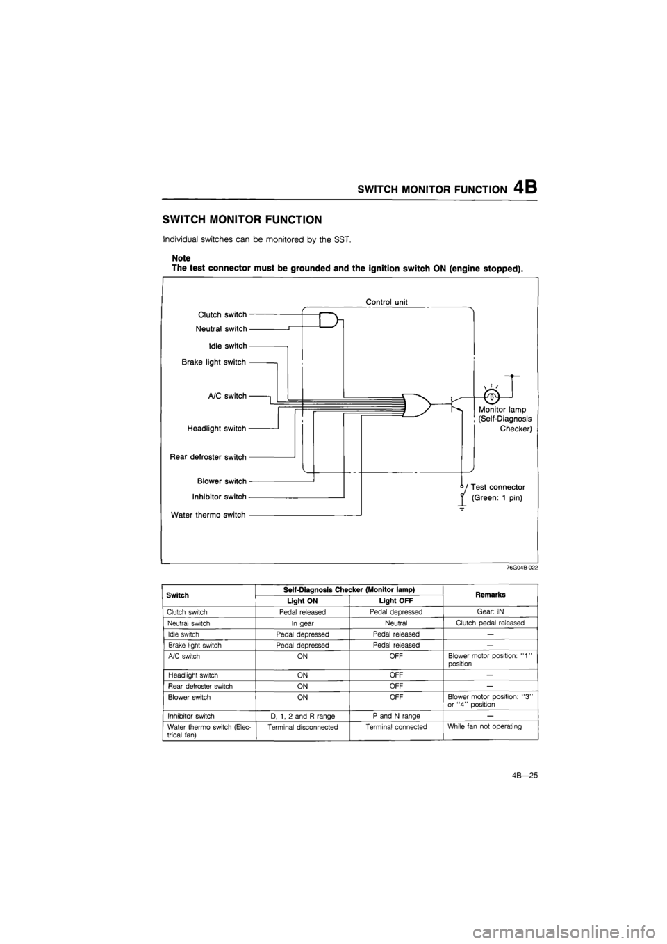
SWITCH MONITOR FUNCTION
Individual switches can be monitored by the SST.
Note
The test connector must be grounded and the ignition switch ON (engine stopped).
Control unit
76G04B-022
Switch Self-Diagnosis Checker (Monitor lamp) Remarks Switch Light ON Light OFF Remarks
Clutch switch Pedal released Pedal depressed Gear:
IN
Neutral switch In gear Neutral Clutch pedal released
Idle switch Pedal depressed Pedal released
—
Brake light switch Pedal depressed Pedal released
—
A/C switch ON OFF Blower motor position:
"1"
position
Headlight switch ON OFF
—
Rear defroster switch ON OFF
—
Blower switch ON OFF Blower motor position:
"3"
or
"4"
position
Inhibitor switch D,
1, 2
and
R
range P and
N
range
—
Water thermo switch (Elec-trical fan) Terminal disconnected Terminal connected While fan
not
operating
4B-25