1987 MAZDA 626 change wheel
[x] Cancel search: change wheelPage 67 of 1865
REMOVAL 1A
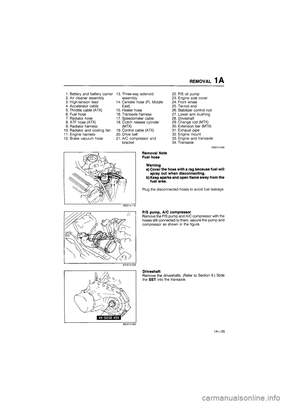
1. Battery and battery carrier 13. Three-way solenoid 22. P/S oil pump
2. Air cleaner assembly assembly 23. Engine side cover
3. High-tension lead 14. Canister hose (Fl, Middle 24. Front wheel
4. Accelerator cable East) 25. Tie-rod end
5. Throttle cable (ATX) 15. Heater hose 26. Stabilizer control rod
6. Fuel hose 16. Transaxle harness 27. Lower arm bushing
7. Radiator hose 17. Speedometer cable 28. Driveshaft
8. ATF hose (ATX) 18. Clutch release cylinder 29. Change rod (MTX)
9. Radiator harness (MTX) 30. Extension bar (MTX)
10. Radiator and cooling fan 19. Control cable (ATX) 31. Exhaust pipe
11. Engine harness 20. Drive belt 32. Engine mount
12. Brake vacuum hose 21. A/C compressor and 33. Engine and transaxle
bracket 34. Transaxle
76G01A-046
Removal Note
Fuel hose
Warning
a) Cover the hose with a rag because fuel will
spray out when disconnecting.
b) Keep sparks and open flame away from the
fuel area.
Plug the disconnected hoses to avoid fuel leakage.
76G01A-11E
P/S pump, A/C compressor
Remove the P/S pump and A/C compressor with the
hoses still connected to them, secure the pump and
compressor as shown in the figure.
67U01X-029
Driveshaft
Remove the driveshafts. (Refer to Section 9.) Slide
the SST into the transaxle.
86U01X-060
1A—35
Page 154 of 1865

REMOVAL 1B
1. Battery and battery carrier
2. Air cleaner assembly
3. High-tension lead
4. Accelerator cable
5. Fuel hose
6. Radiator hose
7. Radiator harness
8. Radiator and electric fan
9. EGI harness
10. Engine harness
11. Brake vacuum hose
12. Canister hose (Unleaded
fuel)
13. Heater hose
14. Transaxle harness
15. Speedometer cable
16. Clutch release cylinder
17. Drive belt
18. A/C compressor and
bracket
19. P/S oil pump
20. Engine side cover
21. Front wheel
22. Tie-rod end
23. Stabilizer control rod
24. Lower arm bushing
25. Driveshaft
26. Change rod
27. Extension bar
28. Exhaust pipe
29. Engine mount
30. Engine and transaxle
31. Transaxle
76G01B-037
Removal Note
Fuel hose
Warning
a) Cover the hose with a rag because fuel will
spray out when disconnecting.
b) Keep sparks and open flame away from the
fuel area.
Plug the disconnected hoses to avoid fuel leakage.
76G01A-11£
P/S pump, A/C compressor
Remove the P/S pump and A/C compressor with the
hoses still connected to them, secure the pump and
compressor as shown in the figure.
67U01X-029
Driveshaft
Remove the driveshafts. (Refer to Section 9.) Slide
the SST into the transaxle.
86U01X-060
1B—23
Page 243 of 1865

REMOVAL 1C
REMOVAL
1. Disconnect the negative battery cable.
2. Drain the engine oil and coolant.
3. Remove in the sequence shown in the figure referring to the removal note for specially marked parts.
76G01C-071
1. Battery and battery carrier
2. Accelerator cable
3. Air cleaner assembly
4. Radiator harness
5. Radiator hose
6. Radiator and cooling fan
7. Brake vacuum hose
8. Intercooler pipe and hose*
9. Fuel hose
10. Drive belt cover
Note
11. P/S pump
12. No.4 engine mount
13. Clutch release cylinder
14. Speedometer cable
15. Transaxle harness
16. A/C compressor
17. Engine harness
18. Heater hose
19. Front wheel
20. Engine side cover
21. Tie-rod end
22. Stabilizer control rod
23. Lower arm bushing
24. Driveshaft
25. Change rod
26. Extension bar
27. Exhaust pipe and stay
28. Engine mount
29. Engine and transaxle
30. Transaxle
marked parts are equipped only for RF-CX.
1C-31
Page 1479 of 1865
ANTI-LOCK BRAKE SYSTEM (ABS) 1 1
86U11X-1C
Q-08
Q-08
Fail-safe relay
B B BG
(Q-08)(Q-09)
V
BL BR
Motor relay
B BR (Q-09)
LO RY
View from male-pin side
86U11X-167
76G11X-096
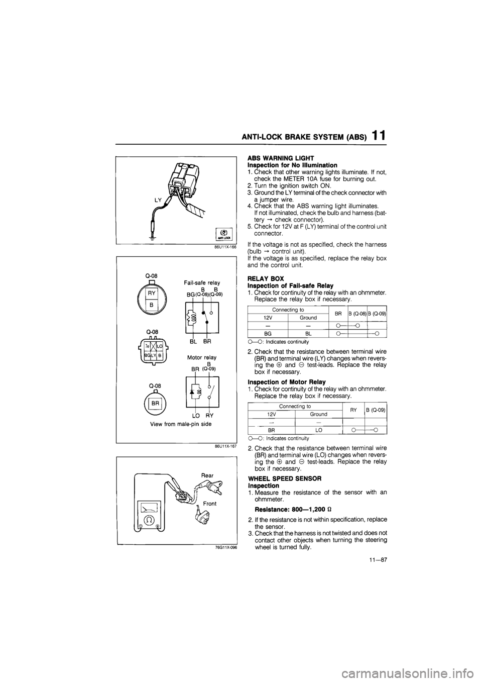
ABS WARNING LIGHT
Inspection for No Illumination
1. Check that other warning lights illuminate. If not,
check the METER 10A fuse for burning out.
2. Turn the ignition switch ON.
3. Ground the LY terminal
of
the check connector with
a jumper wire.
4. Check that the ABS warning light illuminates.
If not illuminated, check the bulb and harness (bat-
tery -» check connector).
5. Check for 12V at F (LY) terminal of the control unit
connector.
If the voltage is not as specified, check the harness
(bulb control unit).
If the voltage is as specified, replace the relay box
and the control unit.
RELAY BOX
Inspection of Fail-safe Relay
1. Check for continuity of the relay with an ohmmeter.
Replace the relay box if necessary.
Connecting to BR B (Q-08) B (Q-09) 12V Ground BR B (Q-08) B (Q-09)
— — O— —O
BG BL O— —O
O—O: Indicates continuity
2. Check that the resistance between terminal wire
(BR) and terminal wire (LY) changes when revers-
ing the © and © test-leads. Replace the relay
box if necessary.
Inspection of Motor Relay
1. Check for continuity of the relay with an ohmmeter.
Replace the relay box if necessary.
Connecting to RY B (Q-09) 12V Ground RY B (Q-09)
-—
BR LO o— O
O—O: Indicates continuity
2. Check that the resistance between terminal wire
(BR) and terminal wire (LO) changes when revers-
ing the © and © test-leads. Replace the relay
box if necessary.
WHEEL SPEED SENSOR
Inspection
1. Measure the resistance of the sensor with an
ohmmeter.
Resistance: 800—1,200 0
2. If the resistance is not within specification, replace
the sensor.
3. Check that the harness is not twisted and does not
contact other objects when turning the steering
wheel is turned fully.
11-87
Page 1480 of 1865
1 1 ANTI-LOCK BRAKE SYSTEM (ABS)
86U11X-170
86U11X-171
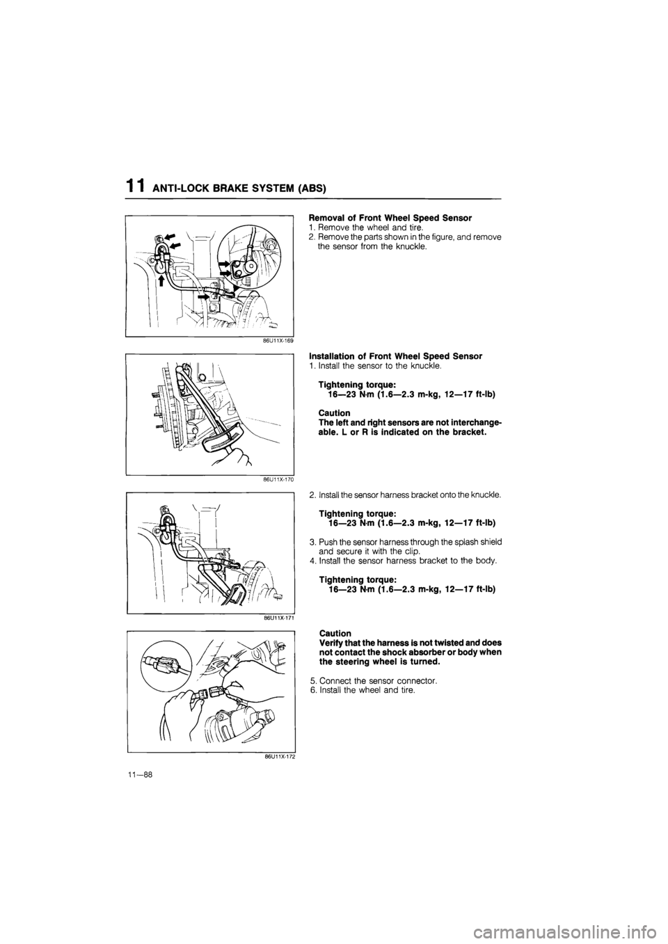
Removal of Front Wheel Speed Sensor
1. Remove the wheel and tire.
2. Remove the parts shown in the figure, and remove
the sensor from the knuckle.
Installation of Front Wheel Speed Sensor
1. Install the sensor to the knuckle.
Tightening torque:
16—23 N m (1.6—2.3 m-kg, 12—17 ft-lb)
Caution
The left and right sensors are not interchange-
able. L or R is indicated on the bracket.
2. Install the sensor harness bracket onto the knuckle.
Tightening torque:
16—23 Nm (1.6—2.3 m-kg, 12—17 ft-lb)
3. Push the sensor harness through the splash shield
and secure it with the clip.
4. Install the sensor harness bracket to the body.
Tightening torque:
16—23 Nm (1.6—2.3 m-kg, 12—17 ft-lb)
Caution
Verify that the harness is not twisted and does
not contact the shock absorber or body when
the steering wheel is turned.
5. Connect the sensor connector.
6. Install the wheel and tire.
86U11X-172
11-88
Page 1481 of 1865
ANTI-LOCK BRAKE SYSTEM (ABS) 1 1
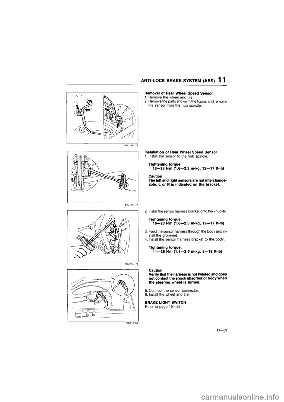
Removal of Rear Wheel Speed Sensor
1. Remove the wheel and tire.
2. Remove the parts shown in the figure, and remove
the sensor from the hub spindle.
86U11X-173
86U11X-174
86U11X-175
Installation of Rear Wheel Speed Sensor
1. Install the sensor to the hub spindle.
Tightening torque:
16—23 N m (1.6—2.3 m-kg, 12—17 ft-lb)
Caution
The left and right sensors are not interchange-
able. L or R is indicated on the bracket.
2. Install the sensor harness bracket onto the knuckle.
Tightening torque:
16—23 Nm (1.6—2.3 m-kg, 12—17 ft-lb)
3. Feed the sensor harness through the body and in-
stall the gromrnet.
4. Install the sensor harness bracket to the body.
Tightening torque:
11—26 N m (1.1—2.6 m-kg, 8—19 ft-lb)
Caution
Verify that the harness is not twisted and does
not contact the shock absorber or body when
the steering wheel is turned.
5. Connect the sensor connector.
6. Install the wheel and tire.
BRAKE LIGHT SWITCH
Refer to page 15—58.
76G11X-060
11-89
Page 1497 of 1865
1 2 WHEELS AND TIRES
Regarding tire replacement:
Note the following points when tires are to be removed from or mounted onto the wheels.
1. Be careful not to scratch the tire bead, the rim bead, or the edge of the rim.
2. Apply a soapy solution to the tire bead and the edge of the rim.
3. Use a wire brush, sandpaper, or cloth to clean and remove all rust, dirt, etc., from the rim edge
and the rim bead. For aluminum wheels, use only a cloth for this purpose; never use a wire brush
or sandpaper.
4. Remove any pebbles, glass, nails, etc., embedded in the tire tread.
5. Be sure the air valve is installed correctly.
6. After mounting a tire onto a wheel, inflate the tire to 250—300 kPa (2.55—3.06 kg/cm2,35.55—42.66
psi). Check to be sure that the bead is seated correctly onto the rim and that there are no air leaks.
Then reduce the pressure to the specified level.
7. If a tire iron is used to change a tire on an aluminum wheei, be sure to use a piece of rubber be-
tween the iron lever and the wheel in order to avoid damage to the wheel. Work should be done
on a rubber mat, not on a hard or rough surface. 76G12X-006
12—6
Page 1547 of 1865
1 3 FRONT WHEEL ALIGNMENT
FRONT WHEEL ALIGNMENT
86U13X-108
69G10X-031
Pre-inspection
1. Check the tire inflation and bring to the recom-
mended pressure.
2. Inspect the front wheel bearing play and correct,
it if necessary.
3. Inspect the wheel and tire runout.
4. Inspect the ball joints and steering linkage for any
excessive looseness.
5. The vehicle must be on level ground and have no
luggage or passenger load.
6. The difference in height between the left and right
sides from the center of the wheel to the fender
brim must be within 10 mm (0.39 in).
Caution
a) Front and rear wheel alignment should be
checked simultaneously. If adjustment is
made to either the front or rear wheels,
recheck the alignment, particularly toe-in,
on all other wheels.
b) Check and adjust the steering angle trans-
fer shaft after adjusting the front wheel
alignment. (Refer to Section 10)
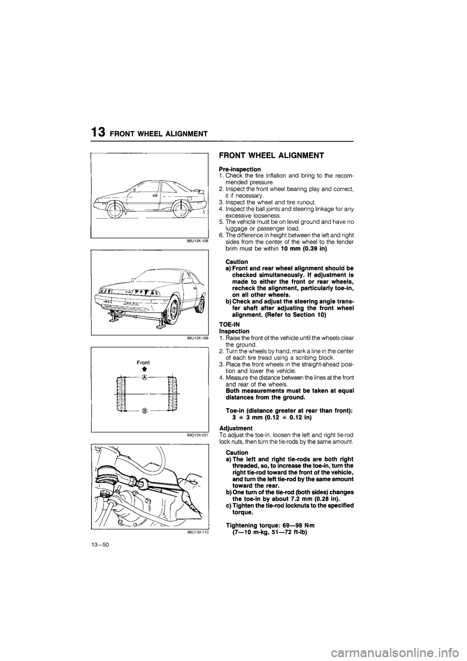
TOE-IN
Inspection
1. Raise the front of the vehicle until the wheels clear
the ground.
2. Turn the wheels by hand, mark a line in the center
of each tire tread using a scribing block.
3. Place the front wheels in the straight-ahead posi-
tion and lower the vehicle.
4. Measure the distance between the lines at the front
and rear of the wheels.
Both measurements must be taken at equal
distances from the ground.
Toe-in (distance greater at rear than front):
3 ± 3 mm (0.12 ± 0.12 in)
Adjustment
To adjust the toe-in, loosen the left and right tie-rod
lock nuts, then turn the tie-rods by the same amount.
Caution
a) The left and right tie-rods are both right
threaded, so, to increase the toe-in, turn the
right tie-rod toward the front of the vehicle,
and turn the left tie-rod by the same amount
toward the rear.
b) One turn of the tie-rod (both sides) changes
the toe-in by about 7.2 mm (0.28 in).
c) Tighten the tie-rod locknuts to the specified
torque.
Tightening torque: 69—98 N-m
(7—10 m-kg, 51—72 ft-lb) 86U13X-110
13-50