1987 MAZDA 626 reset
[x] Cancel search: resetPage 475 of 1865
TROUBLESHOOTING WITH SST 4B
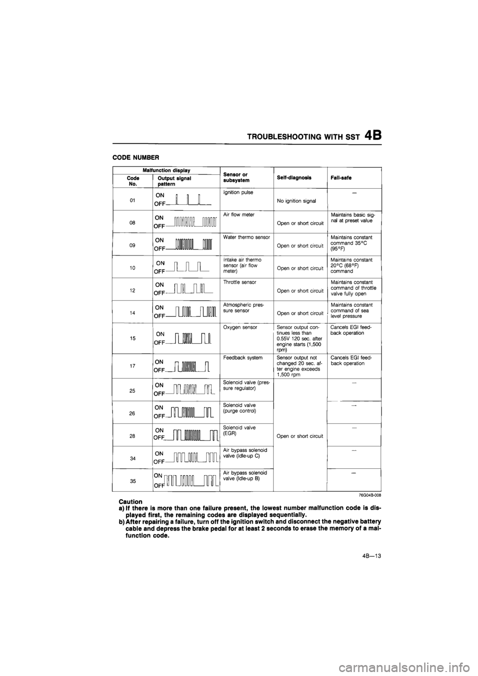
CODE NUMBER
Malfunction display
Self-diagnosis Fail-safe Code
No. Output signal pattern subsystem Self-diagnosis Fail-safe
01
ON
OFF
Ignition pulse
No ignition signal
08
Air flow meter
Open
or
short circuit
Maintains basic sig-
nal
at
preset value
09
1 111
Water thermo sensor
Open
or
short circuit
Maintains constant command 35°C (95 °F)
10
Intake
air
thermo sensor (air flow meter) Open
or
short circuit
Maintains constant 20°C (68°F) command
12
£_IUILJIIL
Throttle sensor
Open
or
short circuit
Maintains constant
command
of
throttle
valve fully open
14
OFF
TL
I I nil
Atmospheric pres-
sure sensor Open
or
short circuit
Maintains constant command
of
sea level pressure
15
oTp m 11 [U
Oxygen sensor Sensor output con-tinues less than 0.55V 120 sec. after engine starts (1,500 rpm)
Cancels EG
I
feed-
back operation
17
SLJlMJl
Feedback system Sensor output
not
changed
20
sec.
af-
ter engine exceeds 1,500 rpm
Cancels EGI feed-back operation
25
^JMLJl
Solenoid valve (pres-
sure regulator)
Open
or
short circuit
26
SUUBUIL
Solenoid valve (purge control)
Open
or
short circuit 28
£ mi in nr
Solenoid valve
(EGR) Open
or
short circuit
34
^jmiUTT
Air bypass solenoid
valve (Idle-up
C)
Open
or
short circuit
35
0Nnnnj OFFU u UUU
"fin nnr
Air bypass solenoid
valve (Idle-up
B)
Open
or
short circuit
76G04B-008
Caution
a) If there is more than one failure present, the lowest number malfunction code is dis-
played first, the remaining codes are displayed sequentially.
b) After repairing a failure, turn off the ignition switch and disconnect the negative battery
cable and depress the brake pedal for at least 2 seconds to erase the memory of a mal-
function code.
4B-13
Page 494 of 1865
4B INTAKE AIR SYSTEM
69G04A-059
86U04A-053
79G04D-084
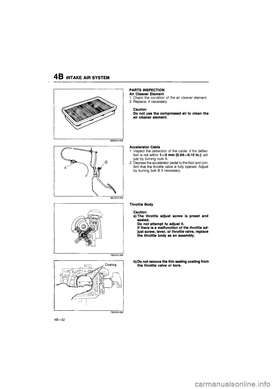
PARTS INSPECTION
Air Cleaner Element
1. Check the condition of the air cleaner element.
2. Replace, if necessary.
Caution
Do not use the compressed air to clean the
air cleaner element.
Accelerator Cable
1. Inspect the deflection of the cable. If the deflec-
tion is not within 1—3 mm (0.04—0.12 in.), ad-
just by turning nuts A.
2. Depress the accelerator pedal to the floor and con-
firm that the throttle valve is fully opened. Adjust
by turning bolt B if necessary.
Throttle Body
Caution
a) The throttle adjust screw is preset and
sealed.
Do not attempt to adjust it.
If there is a malfunction of the throttle ad-
just screw, lever, or throttle valve, replace
the throttle body as an assembly.
b) Do not remove the thin sealing coating from
the throttle valve or bore.
79G04D-085
4B-32
Page 576 of 1865

TROUBLESHOOTING WITH SST 4C
Malfunction display
Sensor or subsystem Self-diagnosis Fail-safe Malfunction
code no. Malfunction code output signal pattern
Sensor or subsystem Self-diagnosis Fail-safe
08
Air flow sensor Open or short circuit Maintains basic sig-nal at preset value
09 o°pNp II IIL •
Water thermo sensor Open or short circuit Maintains constant 35°C (95°F) command
11 0°FNFJUUL
Intake air thermo sensor (dynamic chamber)
Short circuit Maintains constant 20°C (68°F) command
12
Throttle sensor Open or short circuit Maintains constant command of throttle valve fully open
15 ON n
OFF •L 01
Oxygen sensor Sensor output con-tinues less than 0.55V 120 sec. after engine starts (1,500 rpm or over)
Cancels
EG I
feed-
back operation
17 ON n
OFF L HI il
Feedback system Sensor output not changed 20 sec. af-ter engine starts (1,500 rpm or over)
Cancels
EG I
feed-
back operation
25 0°nfJU1LJIL
Solenoid valve (pres-sure regulator control)
Open or short circuit
26 2LMJIL
Solenoid valve (No.1 purge control)
Open or short circuit
27 ON nn
OFF | _ •111
-ii-Solenoid valve (No.2
purge control)
Open or short circuit
28 ON nn
OFF L Hi nr
Solenoid valve (EGR)
Open or short circuit
34 ^jmiHum
Solenoid valve (Idle speed control)
Open or short circuit
36 °FFJMI«U
Oxygen sensor relay
Open or short circuit
41 <£jimjiuM
Solenoid valve (Vari-able inertia control)
Open or short circuit
76G04C-018
Caution
a) If there is more than one failure present, the lowest number malfunction code is dis-
played first, the remaining codes are displayed sequentially.
b) After repairing a failure, turn off the ignition switch and disconnect the negative battery
cable and depress the brake pedal for at least 5 seconds to erase the memory of a mal-
function code.
4C—15
Page 595 of 1865
4C INTAKE AIR SYSTEM
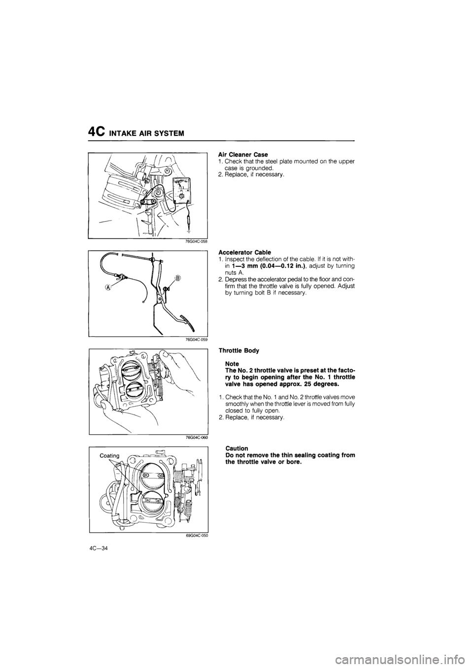
Air Cleaner Case
1. Check that the steel plate mounted on the upper
case is grounded.
2. Replace, if necessary.
76G04C-058
Accelerator Cable
1. Inspect the deflection of the cable. If it is not with-
in 1—3 mm (0.04—0.12 in.), adjust by turning
nuts A.
2. Depress the accelerator pedal to the floor and con-
firm that the throttle valve is fully opened. Adjust
by turning bolt B if necessary.
76G04C-059
Throttle Body
Note
The No. 2 throttle valve is preset at the facto-
ry to begin opening after the No. 1 throttle
valve has opened approx. 25 degrees.
1. Check that the No. 1 and No. 2 throttle valves move
smoothly when the throttle lever is moved from fully
closed to fully open.
2. Replace, if necessary.
76G04C-060
Caution
Do not remove the thin sealing coating from
the throttle valve or bore.
69G04C-050
4C-34
Page 883 of 1865
TROUBLESHOOTING (G4A-EL) 7B
06 4 second period
55 4 second period
63
-*•
4 second period
Repeats above
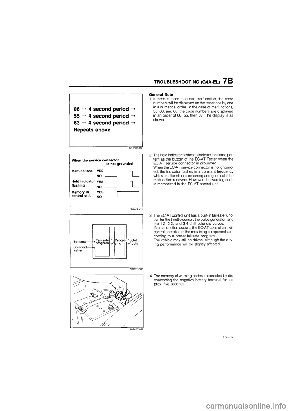
General Note
1. If there is more than one malfunction, the code
numbers will be displayed on the tester one by one
in a numerical order. In the case of malfunctions,
55, 06, and 63, the code numbers are displayed
in an order of 06, 55, then 63. The display is as
shown.
86U07B-018
When the service connector
is not grounded
Malfunctions YES
NO
Hold indicator YES
flashing NQ
YES
NO
Memory in control unit
2. The hold indicator flashes to indicate the same pat-
tern as the buzzer of the EC-AT Tester when the
EC-AT service connector is grounded.
When the EC-AT service connector is not ground-
ed, the indicator flashes in a constant frequency
while a malfunction is occurring and goes out
if
the
malfunction recovers. However, the warning code
is memorized in the EC-AT control unit.
76G07B-015
Sensors-
Solenoid-valve
Fail-safe program Proces--\Out sing -v puts
The EC-AT control unit has a built-in fail-safe func-
tion for the throttle sensor, the pulse generator, and
the 1-2, 2-3, and 3-4 shift solenoid valves.
If a malfunction occurs, the EC-AT control unit will
control operation of the remaining components ac-
cording to a preset fail-safe program.
The vehicle may still be driven, although the driv-
ing performance will be slightly affected.
79G07C-062
4. The memory of warning codes is canceled by dis-
connecting the negative battery terminal for ap-
prox. five seconds.
79G07C-063
7B-17
Page 1321 of 1865
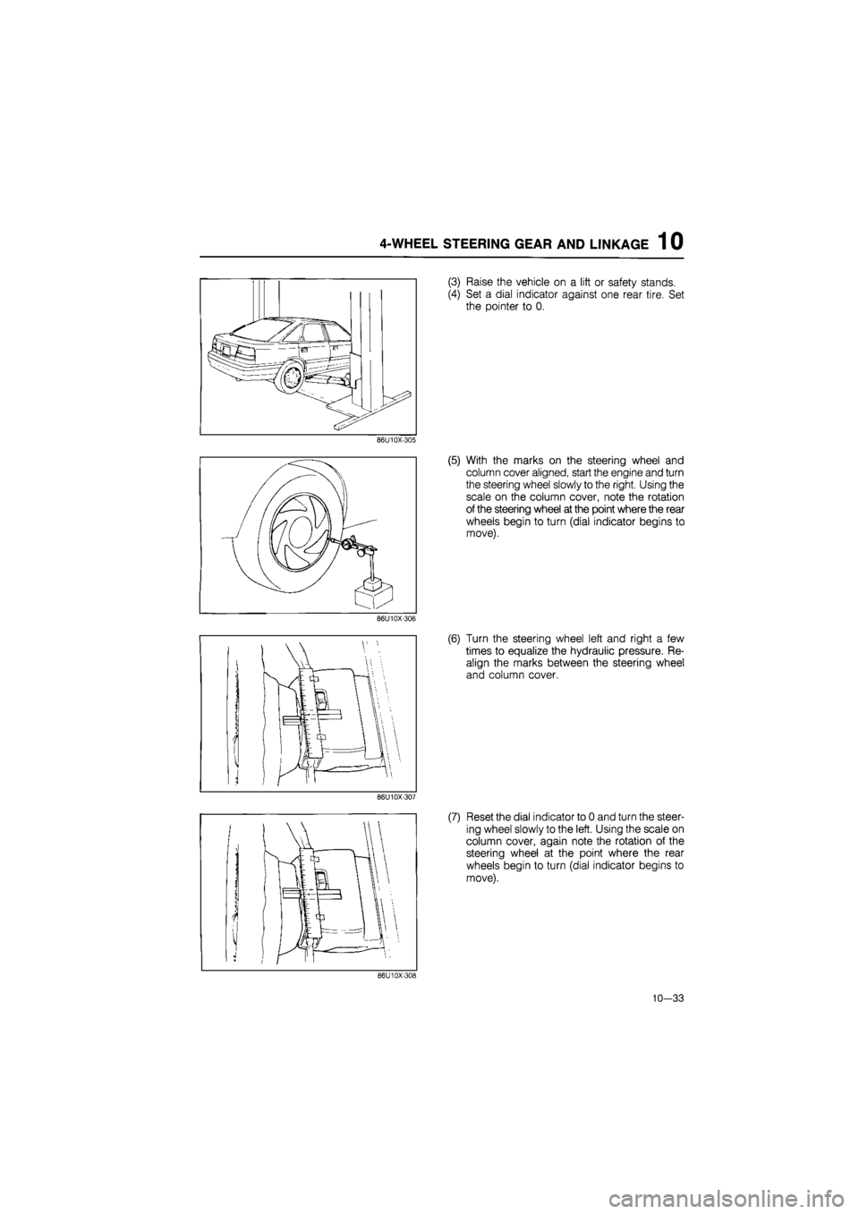
4-WHEEL STEERING GEAR AND LINKAGE 1 0
(3) Raise the vehicle on a lift or safety stands.
(4) Set a dial indicator against one rear tire. Set
the pointer to 0.
86U10X-305
(5) With the marks on the steering wheel and
column cover aligned, start the engine and turn
the steering wheel slowly to the right. Using the
scale on the column cover, note the rotation
of the steering wheel at the point where the rear
wheels begin to turn (dial indicator begins to
move).
86U10X-306
(6) Turn the steering wheel left and right a few
times to equalize the hydraulic pressure. Re-
align the marks between the steering wheel
and column cover.
86U10X-307
(7) Reset the dial indicator to 0 and turn the steer-
ing wheel slowly to the left. Using the scale on
column cover, again note the rotation of the
steering wheel at the point where the rear
wheels begin to turn (dial indicator begins to
move).
86U10X-308
10-33
Page 1666 of 1865
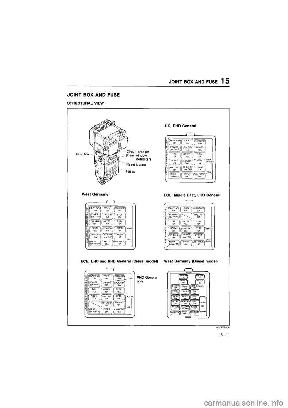
JOINT
BOX AND FUSE
1
5
JOINT BOX AND FUSE
STRUCTURAL VIEW
Joint box Circuit breaker
(Rear window
defroster)
Reset button
Fuses
West Germany
(REAR FOG* RADIO 15A 15A (HEADCLEANER) 20A
(POWER 30A WIND) TAIL (LH) 15A STOP 15A
TAIL (RH) 15A METER 15A TURN 15A
ROOM 15A f(D00R LOCK) [ 30A c
HORN 5A
(AIR COND)' 15A (COOLING 20A FAN>I ENGINE 15A
(REAR 15A WIPER) WIPER 20A (SUN ROOF) [ 15A
ECE, LHD and RHD General (Diesel model)
. Q .
(REAR FOG) 15A J RADIO 15A (rHEADCLEAMEfii I joa J (POWER 1 30A WIND)j (DIM DIP) 15A ( HAZAARD ' I TAIL 15A METER 15A TURN 15A
' ROOM ' ISA j flBOOR LOCKl"1 L STOP 1SA -[(AIR COND) 15A J ' ENGINE 15A
(REAR 15A WIPER) WIPER 20A (SUN ROOF) I 16A
RHD General
only
UK, RHD General
(REAR FOG)
[
15A J
RADIO 15A (HEADCLEANER) 20A
(POWER 30A WIND) (DIM DIP) 15A HAZARD 10A
TAIL 15A METER 10A TURN 15A
ROOM 15A (DOOR LOCK) 30A STOP 15A
(AIR COND) 15A '(COOLING 20A FAN) ENGINE 15A
(REAR 15A WIPER) WIPER 20A (SUN ROOF) [ 15A ,
ECE, Middle East, LHD General
Q
(REAR FOG) 15A J RADIO 15A (HEADCLEANER) 20A
(POWER 30A WIND) HAZARD 10A
TAIL 15A METER 15A TURN 15A
ROOM 5A (DOOR LOCK) 3CA STOP tSA ] (AIR CONO)| . ISA jj| ((COOLING! ( ENGINE 1 J [
BOA
FAfJ)J [ 15A J
(REAR 15AWIP£R), ^ C WIPER "1[SUN HOOF?
1)J
[ 2QA
J
[ 15A
West Germany (Diesel model)
MAIN (fWl
ISA I
MALM (LM1
15A
DIM iLHI
ISA
PEAfl FOCii
I 'SA | RAQIO T5A I
HEAP CLEANEF*
1 I (POWEfl I
3PA WI^D;. TAIL (LH)
15A
)C
TAIL
(DOOR LOC*C|
HOflN 15A Jt 1SA
(
AIR COND)
jy (COOUNQ
gqA FAN)
ENGINE 16A
|fl£AR WlPEFl!
ILJSi '
DEfOO
3 OA
Dtf
WtPEfl
USUNROQF Jl JPA H 15A [
86U15X-006
15-11
Page 1750 of 1865
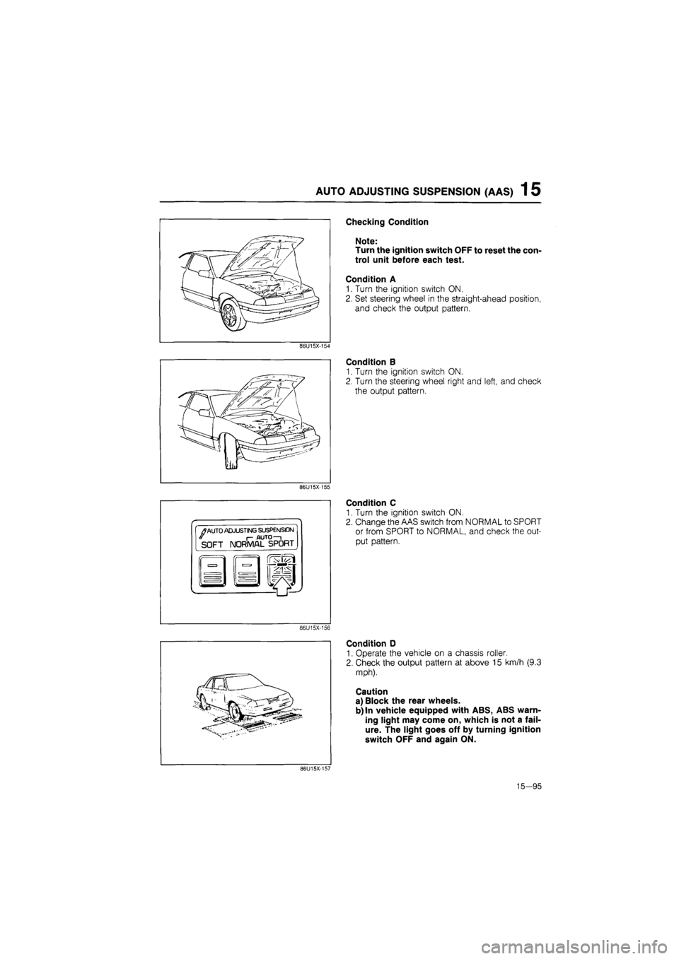
AUTO ADJUSTING SUSPENSION (AAS) 1 5
Checking Condition
Note:
Turn the ignition switch OFF to reset the con-
trol unit before each test.
Condition A
1. Turn the ignition switch ON.
2. Set steering wheel in the straight-ahead position,
and check the output pattern.
86U15X-154
Condition B
1. Turn the ignition switch ON.
2. Turn the steering wheel right and left, and check
the output pattern.
86U15X-155
•
/
AUTO ADJUSTING SUSPENSION I- AUTO—i SOFT NORMAL SPORT
Condition C
1. Turn the ignition switch ON.
2. Change the AAS switch from NORMAL to SPORT
or from SPORT to NORMAL, and check the out-
put pattern.
86U15X-156
Condition D
1. Operate the vehicle on a chassis roller.
2. Check the output pattern at above 15 km/h (9.3
mph).
Caution
a) Block the rear wheels.
b) In vehicle equipped with ABS, ABS warn-
ing light may come on, which is not a fail-
ure. The light goes off by turning ignition
switch OFF and again ON.
86U15X-157
15—95