1987 MAZDA 626 air suspension
[x] Cancel search: air suspensionPage 2 of 1865
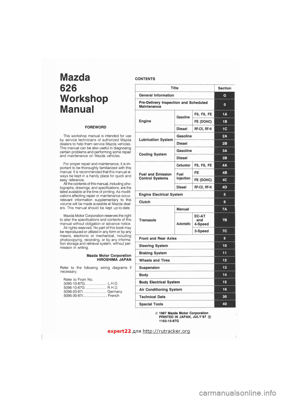
Mazda
626
Workshop
Manual
FOREWORD
This workshop manual is intended for use
by service technicians of authorized Mazda
dealers to help them service Mazda vehicles.
This manual can be also useful in diagnosing
certain problems and performing some repair
and maintenance on Mazda vehicles.
For proper repair and maintenance, it is im-
portant to be thoroughly familiarized with this
manual. It is recommended that this manual al-
ways be kept in a handy place for quick and
easy reference.
All the contents of this manual, including pho-
tographs, drawings, and specifications, are the
latest available at the time of printing. As modifi-
cations affecting repair or maintenance occur,
relevant information supplementary to this
volume will be made available at Mazda deal-
ers. This manual should be kept up-to-date.
Mazda Motor Corporation reserves the right
to alter the specifications and contents of this
manual without obligation or advance notice.
All rights reserved. No part of this book may
be reproduced or utilized in any form or by any
means, electronic or mechanical, including
photocopying, recording, or by any informa-
tion storage and retrieval system, without per-
mission in writing.
Mazda Motor Corporation
HIROSHIMA JAPAN
Refer to the following wiring diagrams if
necessary.
Refer to From No.
5095-10-87 G L.H.D.
5096-10-87 G R.H.D.
5096-20-871 Germany
5095-30-871 French
CONTENTS
Title Section
General Information G
Pre-Delivery Inspection and Scheduled
Maintenance 0
Gasoline F6, F8, FE 1A
Engine
Gasoline
FE (DOHC) 1B
Diesel RF-CX, RF-N 1C
Lubrication System
Gasoline 2A
Lubrication System
Diesel 2B I
Cooling System
Gasoline 3A 1
Cooling System
Diesel 3B
Carburetor F6, F8, FE 4A
Fuel and Emission Fuel FE 4B I
Control Systems Injection FE (DOHC) 4C
Diesel RF-CX, RF-N 4D j
Engine Electrical System 5
Clutch 6
Manual 7A
Transaxle
Automatic
EC-AT
and
4-Speed
7B
3-Speed 7C
Front and Rear Axles 9
Steering System 10
Braking System 11
Wheels and Tires 12
Suspension 13
Body 14 |
Body Electrical System 15
Air Conditioning System 16
Technical Data 30
Special Tools 40
© 1987 Mazda Motor Corporation
PRINTED IN JAPAN, JULY'87 ©
1163-10-87G
expert22 flna http://rutracker.org
Page 11 of 1865
CHASSIS NUMBER LOCATION/ABBREVIATIONS/UNITS G
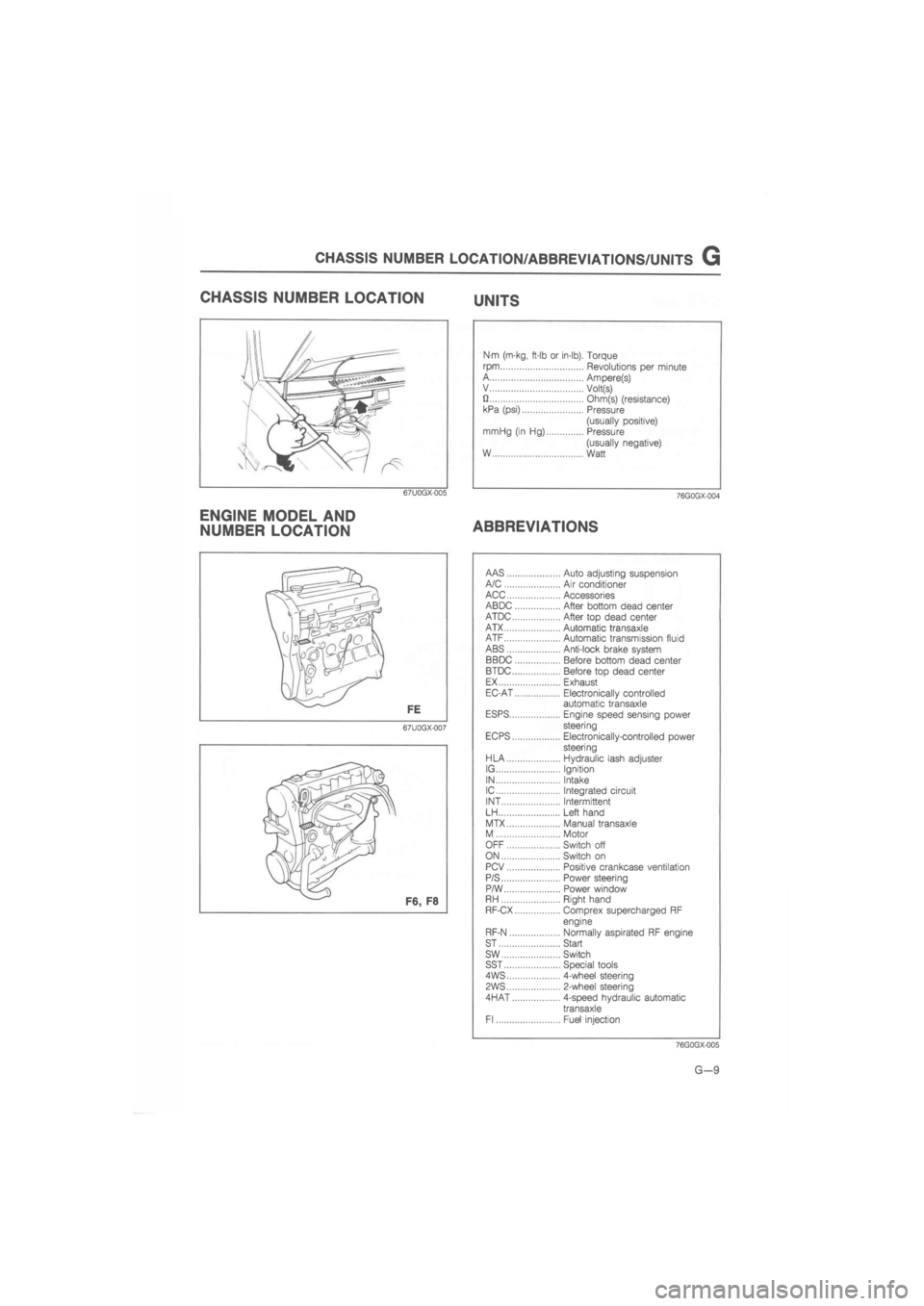
CHASSIS NUMBER LOCATION UNITS
67U0GX-005
ENGINE MODEL AND
NUMBER LOCATION
Nm (m-kg, ft-lb or in-lb). Torque
rpm Revolutions per minute A Ampere(s) V Volt(s) U Ohm(s) (resistance) kPa (psi) Pressure
(usually positive) mrriHg (in Hg) Pressure
(usually negative) W Watt
76G0GX-004
ABBREVIATIONS
67U0GX-007
AAS Auto adjusting suspension A/C Air conditioner ACC Accessories ABDC After bottom dead center ATDC After top dead center ATX Automatic transaxle ATF Automatic transmission fluid ABS Anti-lock brake system BBDC Before bottom dead center BTDC Before top dead center EX Exhaust EC-AT Electronically controlled automatic transaxle ESPS Engine speed sensing power steering EC PS Electronically-controlled power steering HLA Hydraulic lash adjuster IG Ignition IN Intake IC Integrated circuit INT Intermittent LH Left hand
MTX Manual transaxle M Motor OFF Switch off ON Switch on PCV Positive crankcase ventilation P/S Power steering P/W Power window RH Right hand RF-CX Comprex supercharged RF
engine
RF-N Normally aspirated RF engine ST Start sw Switch SST Special tools 4WS 4-wheel steering
PWS 2-wheel steering
4HAT 4-speed hydraulic automatic
transaxle Fl Fuel injection
76GQGX-005
G—9
Page 14 of 1865
0 PRE-DELIVERY INSPECTION
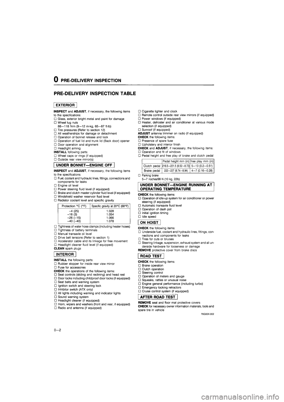
PRE-DELIVERY INSPECTION TABLE
EXTERIOR
INSPECT and ADJUST, if necessary, the following items
to the specifications:
• Glass, exterior bright metal and paint for damage
• Wheel lug nuts
88—118 N m (9—12 m-kg, 65—87 ft-lb)
• Tire pressures (Refer to section 12)
• All weatherstrips for damage or detachment
• Operation of bonnet release and lock
• Operation of fuel lid and trunk lid (Back door) opener
• Door operation and alignment
• Headlight aiming
INSTALL following parts:
• Wheel caps or rings (if equipped)
• Outside rear view mirror(s)
UNDER BONNET—ENGINE OFF
INSPECT and ADJUST, if necessary, the following items
to the specifications:
• Fuel, coolant and hydraulic lines, fittings, connections and
components for leaks
• Engine oil level
• Power steering fluid level (if equipped)
• Brake and clutch master cylinder fluid level (if equipped)
• Windshield washer reservoir fluid level
• Radiator coolant level and specific gravity
Protection °C (°F) Specific gravity at 20°C (68°F)
-4 (25) 1.028
-16(3) 1.054
-26 (-15) 1.066 -40 (-40) 1.078
• Tightness of water hose clamps (including heater hoses)
• Tightness of battery terminals
• Manual transaxle oil level
• Drive belt tensions (Refer to section 1)
• Accelerator cable and its linkage for free movement
• Headlight cleaner fluid level (if equipped)
CLEAN spark plugs
INTERIOR
INSTALL the following parts:
• Rubber stopper for inside rear view mirror
• Fuse for accessories
CHECK the operations of the following items:
• Seat controls (sliding and reclining) and head rest
• Door locks including childproof door locks (if equipped)
• Seat belts and warning system
• Ignition switch and steering lock
• Inhibitor switch (ATX only)
• All lights including warning and indicator lights
• Sound warning system
• Headlight cleaner (if equipped)
• Horn, wipers and washers (front and rear, if equipped)
• Radio and antenna (if equipped)
• Cigarette lighter and clock
• Remote control outside rear view mirrors (if equipped)
• Power windows (if equipped)
• Heater, defroster and air conditioner at various mode
selection (if equipped)
• Sunroof (if equipped)
ADJUST antenna trimmer on radio (if equipped)
CHECK the following items:
• Presence of spare fuse
• Upholstery and interior finish
CHECK and ADJUST, if necessary, the following items:
• Operation and fit of windows
• Pedal height and free play of brake and clutch pedal
Pedal height mm (in) free play mm (in)
Clutch pedal 216.5-221.5 (8.52-8.72) 5-13 (0.2-0.51)
Brake pedal 222-227 (8.74-8.94) 4-7 (0.16-0.28)
• Parking brake
5-7 noches/98 N (10 kg, 22lb)
UNDER BONNET—ENGINE RUNNING AT
OPERATING TEMPERATURE
CHECK the following items:
• Operation of idle-up system for air conditioner or power
steering (if equipped)
• Automatic transaxle fluid level
• Operation of dash pot
• Initial ignition timing
• Idle speed
ON HOIST
CHECK the following items:
• Underside fuel, coolant and hydraulic lines, fittings, con-
nections and components for leaks
• Tires for cuts or bruises
• Steering linkage, suspension, exhaust system and all un-
derside hardware for looseness or damage
REMOVE protective cover from brake discs
ROAD TEST"
CHECK the following items:
• Brake operation
• Clutch operation
• Steering control
• Operation of meters and gauge
• Squeaks, rattles or unusual noise
• Engine general performance (including turbo)
• Emergency locking retractors
• Cruise control system (if equipped)
AFTER ROAD TEST
REMOVE seat and floor mat protective covers
CHECK for necessary owner information materials, tools and
spare tire in vehicle
-76G00X-002
0-2
Page 1494 of 1865
WHEELS AND TIRES 1 2
86U12X-004
\k
y
i jYj
/ <4/
/ v Wear platform
Wear indicators
86U12X-005
(a) (b)
Shoulder wear Center wear
(c)
Feathered edge
(d)
*f tftiit t
Toe-in or toe-out wear Uneven wear
WHEELS AND TIRES
INSPECTION AND ADJUSTMENTS
Check the following, and adjust or replace as
necessary.
1. Air pressure
Check the air pressure of all tires, including the
spare tire, with an air pressure gauge.
(Refer to page 12—2.)
Caution
The air pressure must be measured when the
tire is cold.
2. Tire wear
Specifications
Remaining tread
Ordinary tires: 1.6 mm (0.063 in) min.
(Tire should be replaced if wear indicators are
exposed.)
Snow tires: 50% of tread
(Tire should be replaced if wear indicators are
exposed.)
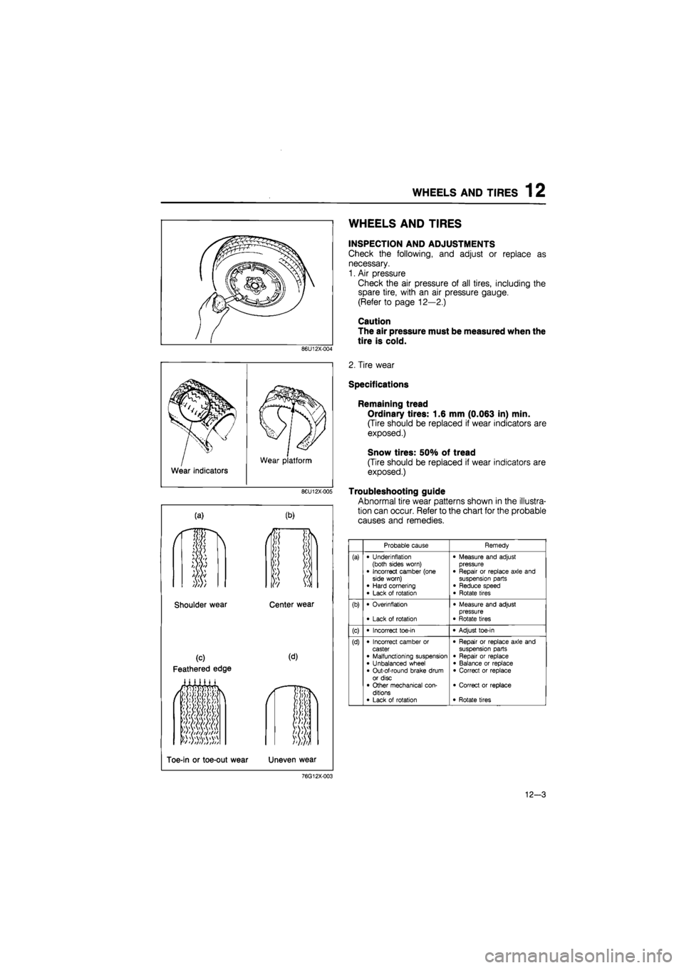
Troubleshooting guide
Abnormal tire wear patterns shown in the illustra-
tion can occur. Refer to the chart for the probable
causes and remedies.
Probable cause Remedy
(a) • Underinflation (both sides worn) • Incorrect camber (one side worn) • Hard cornering • Lack of rotation
• Measure and adjust pressure • Repair or replace axle and suspension parts • Reduce speed • Rotate tires
(b) • Overinflation
• Lack of rotation
• Measure and adjust pressure • Rotate tires
(c) • Incorrect toe-in • Adjust toe-in
(d) • Incorrect camber or caster • Malfunctioning suspension • Unbalanced wheel • Out-of-round brake drum or disc • Other mechanical con-ditions • Lack of rotation
• Repair or replace axle and suspension parts • Repair or replace • Balance or replace • Correct or replace
• Correct or replace
• Rotate tires
76G12X-003
12-3
Page 1656 of 1865
15
BODY ELECTRICAL SYSTEM
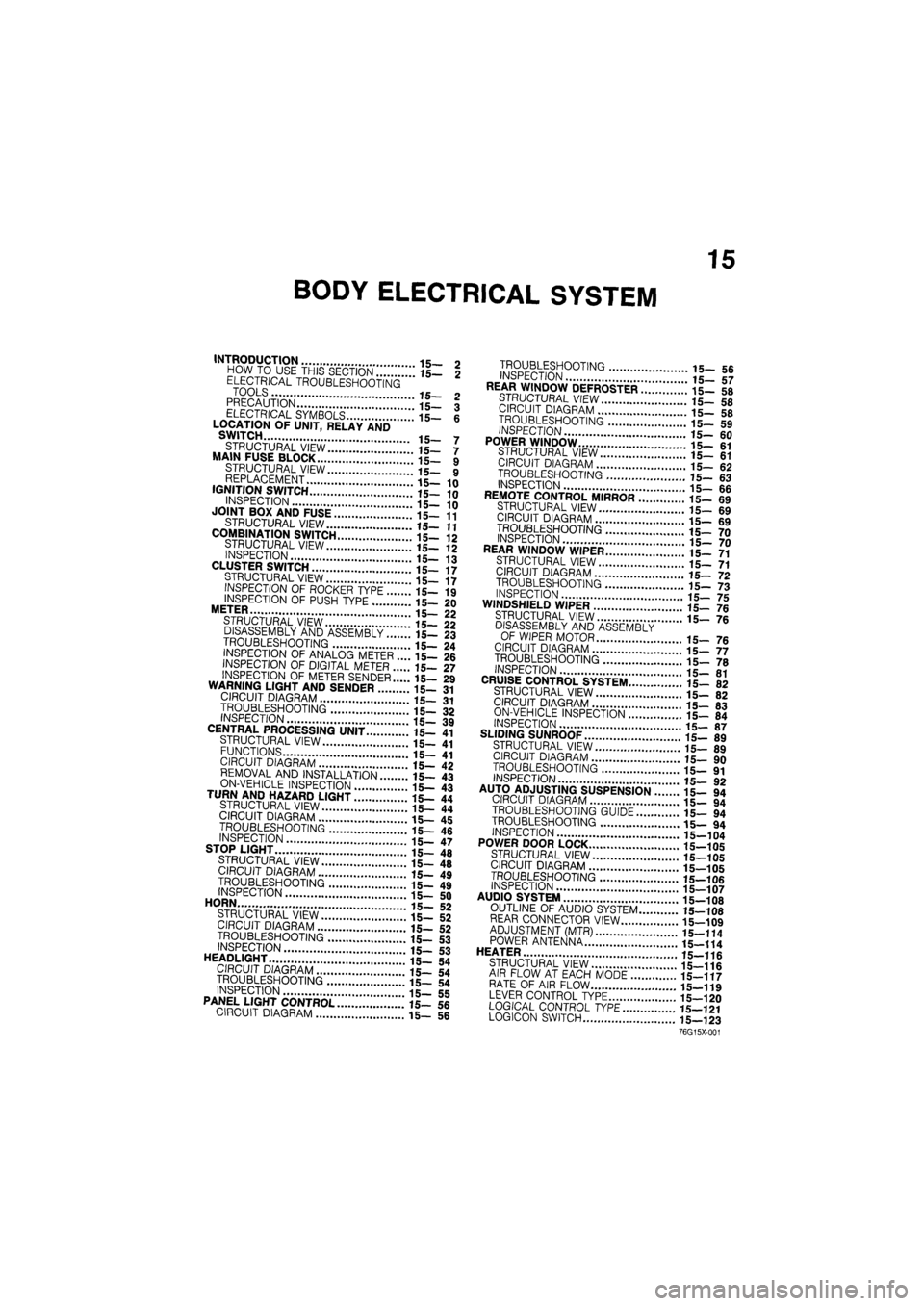
INTRODUCTION 15- 2 HOW TO USE THIS SECTION 15— 2 ELECTRICAL TROUBLESHOOTING TOOLS 15- 2 PRECAUTION 15— 3 ELECTRICAL SYMBOLS 15- 6 LOCATION OF UNIT, RELAY AND SWITCH 15- 7
STRUCTURAL VIEW 15— 7 MAIN FUSE BLOCK 15- 9 STRUCTURAL VIEW 15— 9 REPLACEMENT 15—10 IGNITION SWITCH 15—10
INSPECTION 15— 10 JOINT BOX AND FUSE 15—11
STRUCTURAL VIEW 15—11
COMBINATION SWITCH 15-12 STRUCTURAL VIEW 15- 12 INSPECTION 15— 13 CLUSTER SWITCH 15—17 STRUCTURAL VIEW 15— 17 INSPECTION OF ROCKER TYPE 15— 19
INSPECTION OF PUSH TYPE 15— 20 METER 15— 22 STRUCTURAL VIEW 15— 22 DISASSEMBLY AND ASSEMBLY 15— 23
TROUBLESHOOTING 15— 24 INSPECTION OF ANALOG METER .... 15— 26 INSPECTION OF DIGITAL METER 15— 27
INSPECTION OF METER SENDER 15— 29 WARNING LIGHT AND SENDER 15- 31 CIRCUIT DIAGRAM 15— 31
TROUBLESHOOTING 15- 32 INSPECTION 15— 39 CENTRAL PROCESSING UNIT 15— 41 STRUCTURAL VIEW 15— 41 FUNCTIONS 15- 41 CIRCUIT DIAGRAM 15— 42 REMOVAL AND INSTALLATION 15— 43
ON-VEHICLE INSPECTION 15- 43 TURN AND HAZARD LIGHT 15- 44 STRUCTURAL VIEW 15— 44 CIRCUIT DIAGRAM 15— 45
TROUBLESHOOTING 15- 46 INSPECTION 15— 47 STOP LIGHT 15— 48
STRUCTURAL VIEW 15— 48 CIRCUIT DIAGRAM 15— 49
TROUBLESHOOTING 15- 49 INSPECTION 15- 50 HORN 15— 52 STRUCTURAL VIEW 15— 52 CIRCUIT DIAGRAM 15— 52 TROUBLESHOOTING 15— 53 INSPECTION 15-53 HEADLIGHT 15— 54 CIRCUIT DIAGRAM 15— 54 TROUBLESHOOTING 15— 54 INSPECTION 15— 55 PANEL LIGHT CONTROL 15— 56 CIRCUIT DIAGRAM 15— 56
TROUBLESHOOTING 15_ 5fi INSPECTION 17 REAR WINDOW DEFROSTER ..i".'! 15- 58
STRUCTURAL VIEW 15-5fl CIRCUIT DIAGRAM 15_ «
TROUBLESHOOTING '.. 15_ 59
INSPECTION
15-60 POWER WINDOW 15-61 STRUCTURAL VIEW il_ «1 CIRCUIT DIAGRAM 15_ 62 TROUBLESHOOTING 15- «3 INSPECTION 15-66 REMOTE CONTROL MIRROR ........15- 69 STRUCTURAL VIEW 15-69 CIRCUIT DIAGRAM 15_ 69
TROUBLESHOOTING 15_ 70 INSPECTION 15_ 70 REAR WINDOW WIPER 15_ 71 STRUCTURAL VIEW 15-71 CIRCUIT DIAGRAM .'.'.'...' 15_ 72
TROUBLESHOOTING 15-73 INSPECTION 15-75 WINDSHIELD WIPER 15-76 STRUCTURAL VIEW ' ' 15— 7e
DISASSEMBLY AND ASSEMBLY OF WIPER MOTOR 15_ 76 CIRCUIT DIAGRAM 15-77 TROUBLESHOOTING " " 15— 70 INSPECTION 15-81 CRUISE CONTROL SYSTEM 15- 82 STRUCTURAL VIEW 15-82 CIRCUIT DIAGRAM 15-83 ON-VEHICLE INSPECTION \..\m 15- 84 INSPECTION 15-87 SLIDING SUNROOF 15-89 STRUCTURAL VIEW 15_ 89 CIRCUIT DIAGRAM i5_ 90
TROUBLESHOOTING 15— 91 INSPECTION 15_ 90 AUTO ADJUSTING SUSPENSION 15— 94
CIRCUIT DIAGRAM 15- 94
TROUBLESHOOTING GUIDE 15— 94
TROUBLESHOOTING 15— 94
INSPECTION 15-104
POWER DOOR LOCK 15-105
STRUCTURAL VIEW 15-105
CIRCUIT DIAGRAM 15-105
TROUBLESHOOTING 15-106 INSPECTION 15-107 AUDIO SYSTEM " 15_108 OUTLINE OF AUDIO SYSTEM 15-108 REAR CONNECTOR VIEW 15-109 ADJUSTMENT (MTR) 15—114 POWER ANTENNA 15-114 HEATER J
STRUCTURAL VIEW 15-116 AIR FLOW AT EACH MODE 15-117 RATE OF AIR FLOW 15-119 LEVER CONTROL TYPE 15-120 LOGICAL CONTROL
TYPE
15—121 LOGICON SWITCH 15—123
76G15X-001
Page 1753 of 1865
1 5 AUTO ADJUSTING SUSPENSION
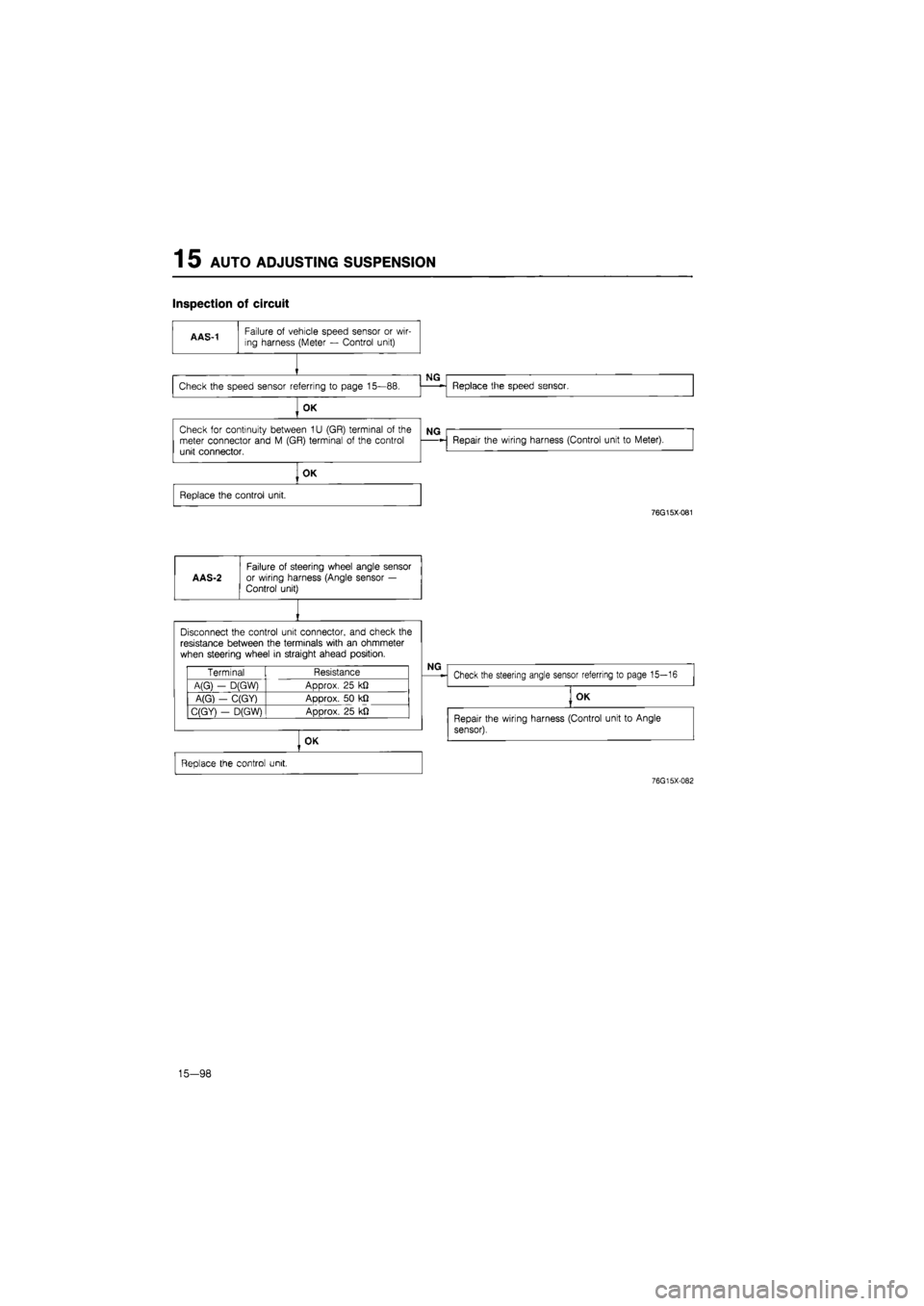
Inspection of circuit
OK
Check
for
continuity between
1U
(GR) terminal
of
the meter connector and
M
(GR) terminal
of
the control unit connector.
Repair the wiring harness (Control unit
to
Meter).
OK
Replace the control unit.
76G15X-081
AAS-2
Failure
of
steering wheel angle sensor
or wiring harness (Angle sensor
—
Control unit)
I
Disconnect the control unit connector, and check
the
resistance between the terminals with
an
ohmmeter
when steering wheel
in
straight ahead position.
Terminal Resistance
A(G)
-
D(GW) ADDrox.
25 kfi
A(G)
-
C(GY) Approx.
50 kfl
C(GY^
-
D(G\M ADorox.
25 kfi
OK
Replace the control unit.
76G15X-082
15-98
Page 1754 of 1865
AUTO ADJUSTING SUSPENSION
(AAS) 1 5
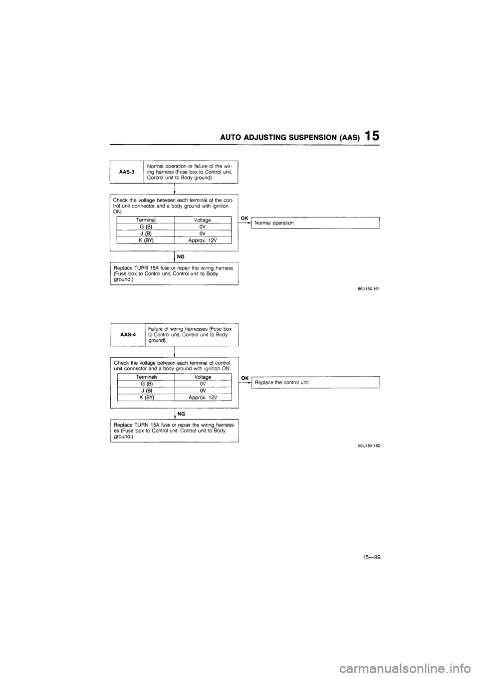
AAS-3
Normal operation
or
failure
of
the wir-ing harness (Fuse box
to
Control unit, Control unit
to
Body ground)
Check the voltage between each terminal
of
the con-trol unit connector and
a
body ground with ignition ON.
Terminal Voltage
G(B) OV
J(B) OV
K (BY) Approx.
12V
OK
Normal operation.
NG
Replace TURN 15A fuse
or
repair the wiring harness (Fuse box
to
Control unit, Control unit
to
Body ground.)
86U15X-161
AAS-4
Failure
of
wiring harnesses (Fuse
box
to Control unit, Control unit
to
Body
ground).
Check the voltage between each terminal
of
control unit connector and
a
body ground with ignition
ON.
Terminals Voltage
G (B) OV
J (B) OV
K (BY)
ADDTOX.
12V
OK
Replace the control unit.
NG
Replace TURN 15A fuse
or
repair the wiring harness-
es (Fuse box
to
Control unit, Control unit
to
Body
ground.)
86U15X-162
15-99
Page 1755 of 1865
1 5 AUTO ADJUSTING SUSPENSION (AAS)
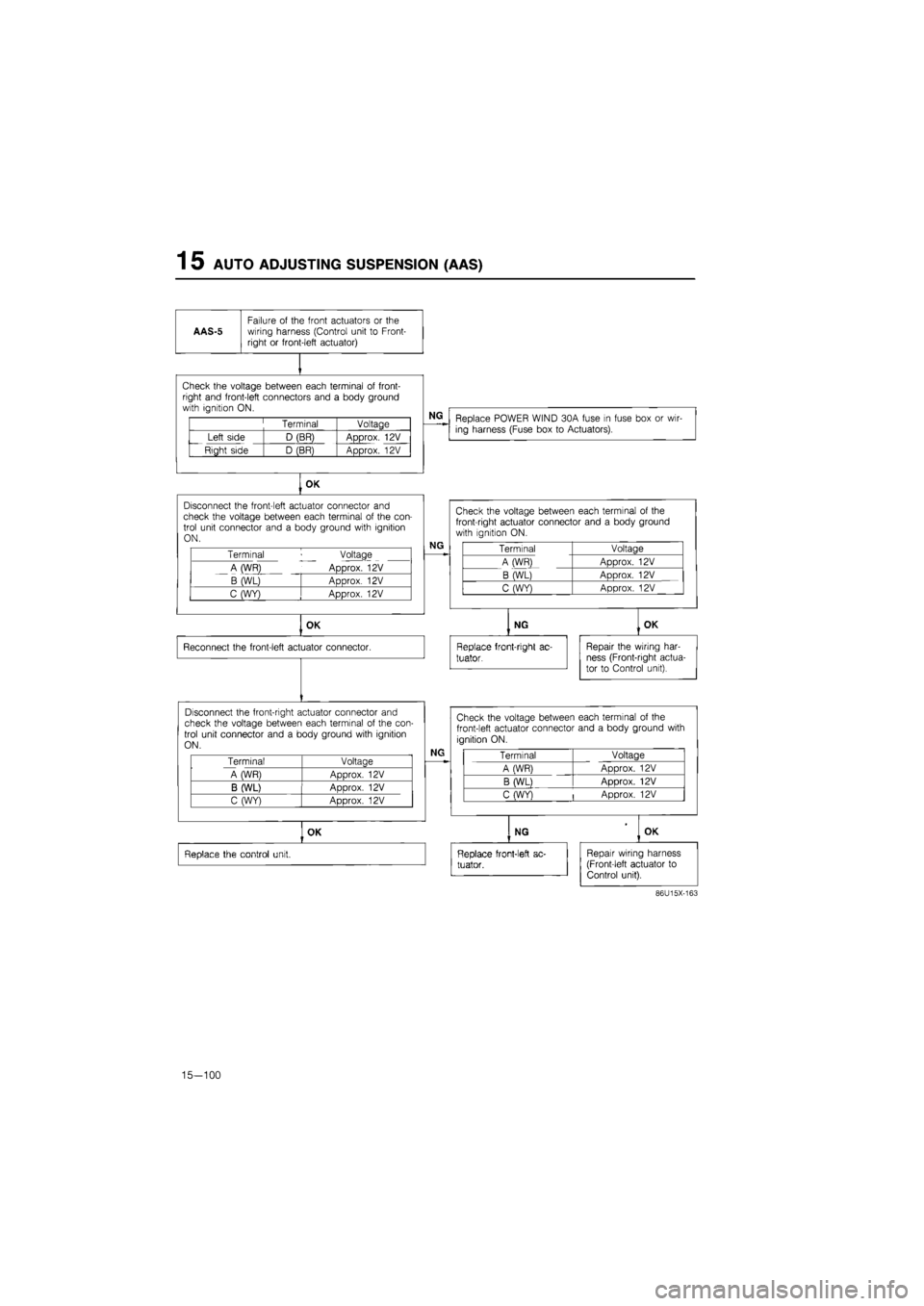
AAS-5
Failure
of
the front actuators
or the
wiring harness (Control unit
to
Front-right
or
front-left actuator)
Check the voltage between each terminal
of
front-right and front-left connectors and
a
body ground with ignition ON.
Terminal Voltage
Left side D (BR) Approx.
12V
Right side D (BR) Approx.
12V
NG
Replace POWER WIND 30A fuse
in
fuse box
or
wir-ing harness (Fuse box
to
Actuators).
OK
Disconnect the front-left actuator connector
and
check the voltage between each terminal
of
the con-trol unit connector and
a
body ground with ignition ON.
Terminal Voltage
A (WR) Approx.
12V
B (WL) Approx.
12V
C (WY) Approx.
12V
NG
OK
Reconnect the front-left actuator connector.
Disconnect the front-right actuator connector and check the voltage between each terminal
of
the con-trol unit connector and
a
body ground with ignition ON.
Terminal Voltage
A WR) Aoorox.
12V
B (WL) ADDrox.
12V
C (WY) Approx.
12V
Check the voltage between each terminal
of the
front-right actuator connector and
a
body ground with ignition
ON.
Terminal Voltage
A (WR) Approx.
12V
B (WL) Approx.
12V
C (WY) Approx.
12V
NG
Replace front-right
ac-
tuator.
OK
Repair the wiring har-ness (Front-right actua-tor
to
Control unit).
NG
Check the voltage between each terminal
of
the
front-left actuator connector and
a
body ground with
ignition ON.
Terminal Voltage
A (WR) Approx.
12V
B (WL) Approx.
12V
C (WY)
|
Approx.
12V
OK
Replace the control unit.
NG OK
Replace front-left
ac-
tuator.
Repair wiring harness (Front-left actuator
to
Control unit).
86U15X-163
15-100