Page 1756 of 1865

AUTO ADJUSTING SUSPENSION (AAS) 1 5
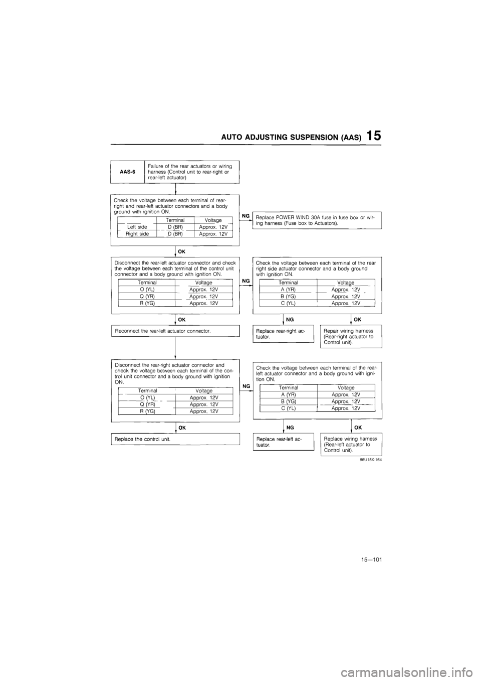
AAS-6
Failure
of
the rear actuators
or
wiring harness (Control unit
to
rear-right
or
rear-left actuator)
vi i11 1vuuuyu tw/v^ii I^CI^I i id i i in I«I wi i
right and rear-left actuator connectors and
a
body ground with ignition ON.
Terminal Voltage
Left side D (BR) Approx.
12V
Right side D (BR) Approx.
12V
NG
Replace POWER WIND 30A fuse
in
fuse box
or
wir-ing harness (Fuse box
to
Actuators).
OK
Disconnect the rear-left actuator connector and check the voltage between each terminal
of
the control unit connector and
a
body ground with ignition ON.
Terminal Voltage
0 (YL) Approx.
12V
Q (YR) Approx.
12V
R (YG) Approx.
12V
NG
OK
Reconnect the rear-left actuator connector.
Disconnect the rear-right actuator connector and check the voltage between each terminal
of
the con-trol unit connector and
a
body ground with ignition ON.
Terminal
'
Voltage
0 (YL)
ADDrox 12V
Q (YR)
ADDrox. 12V
R (YG} Approx.
12V
NG
OK
Replace the control unit.
Check the voltage between each terminal
of
the rear right side actuator connector and
a
body ground with ignition ON.
Terminal Voltage
A (YR) Approx.
12V
B (YG) Approx.
12V
C (YL) Approx.
12V
NG
Replace rear-right ac-
tuator,
OK
Repair wiring harness (Rear-right actuator
to
Control unit).
Check the voltage between each terminal
of
the rear-left actuator connector and
a
body ground with igni-tion ON.
Terminal Voltaae
A (YR) Approx.
12V
B (YG) ADDrox.
12V
C (YL) Approx.
12V
NG
Replace rear-1 eft
ac-
tuator.
OK
Replace wiring harness (Rear-left actuator
to
Control unit).
86U15X-164
15—101
Page 1757 of 1865

1 5 AUTO ADJUSTING SUSPENSION
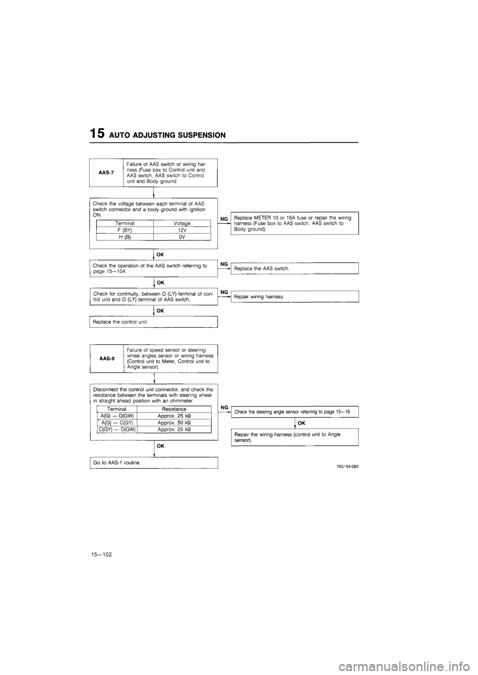
AAS-7
Failure
of
AAS switch
or
wiring har-ness (Fuse box
to
Control unit and AAS switch, AAS switch
to
Control unit and Body ground
Check the voltage between each terminal
of
AAS switch connector and
a
body ground with ignition ON.
Terminal Voltage
F (BY) 12V
H (B) OV
NG Replace METER
10 or
15A fuse
or
repair the wiring harness (Fuse box
to
AAS switch, AAS switch
to
Body ground).
OK
Check the operation
of
the AAS switch referring
to
page 15—104.
, OK
Check
for
continuity, between
D
(LY) terminal
of
con-
trol unit and
D
(LY) terminal
of
AAS switch.
OK
Replace the control unit.
A AS-8
Failure
of
speed sensor
or
steering wheel angles sensor
or
wiring harness (Control unit
to
Meter, Control unit
to
Angle sensor).
NG
Replace the AAS switch.
NG
Repair wiring harness.
Disconnect the control unit connector, and check the resistance between the terminals with steering wheel in straight ahead position with
an
ohmmeter.
Terminal Resistance
A(G)
-
D(GW) Approx.
25
k£2
' A(G}
-
C(GY) Approx.
50 kfl
C(GY)
-
D(GW) Approx.
25
kJ2
NG
Check the steering angle sensor referring
to
page 15—16
OK
Go
to
AAS-1 routine.
OK
Repair the wiring harness (control unit
to
Angle
sensor).
76G15X-083
15-102
Page 1758 of 1865
AUTO ADJUSTING SUSPENSION 1 5
AAS-9
Failure of speed sensor or wiring har-ness (Control unit to Meter, Fuse box to Control unit, Control unit to Body ground)
Replace METER 10 or 15A fuse or repair the wiring harness (Fuse box to Control unit, Control unit to Body ground).
Check the voltage between each terminal of control
unit connector and a body ground with ignition ON.
Terminal Voltage
G (B) OV
J (B) OV
K (BY) Approx. 12V
OK
Go to AAS-1 routine.
76G15X-084
15—103
Page 1852 of 1865

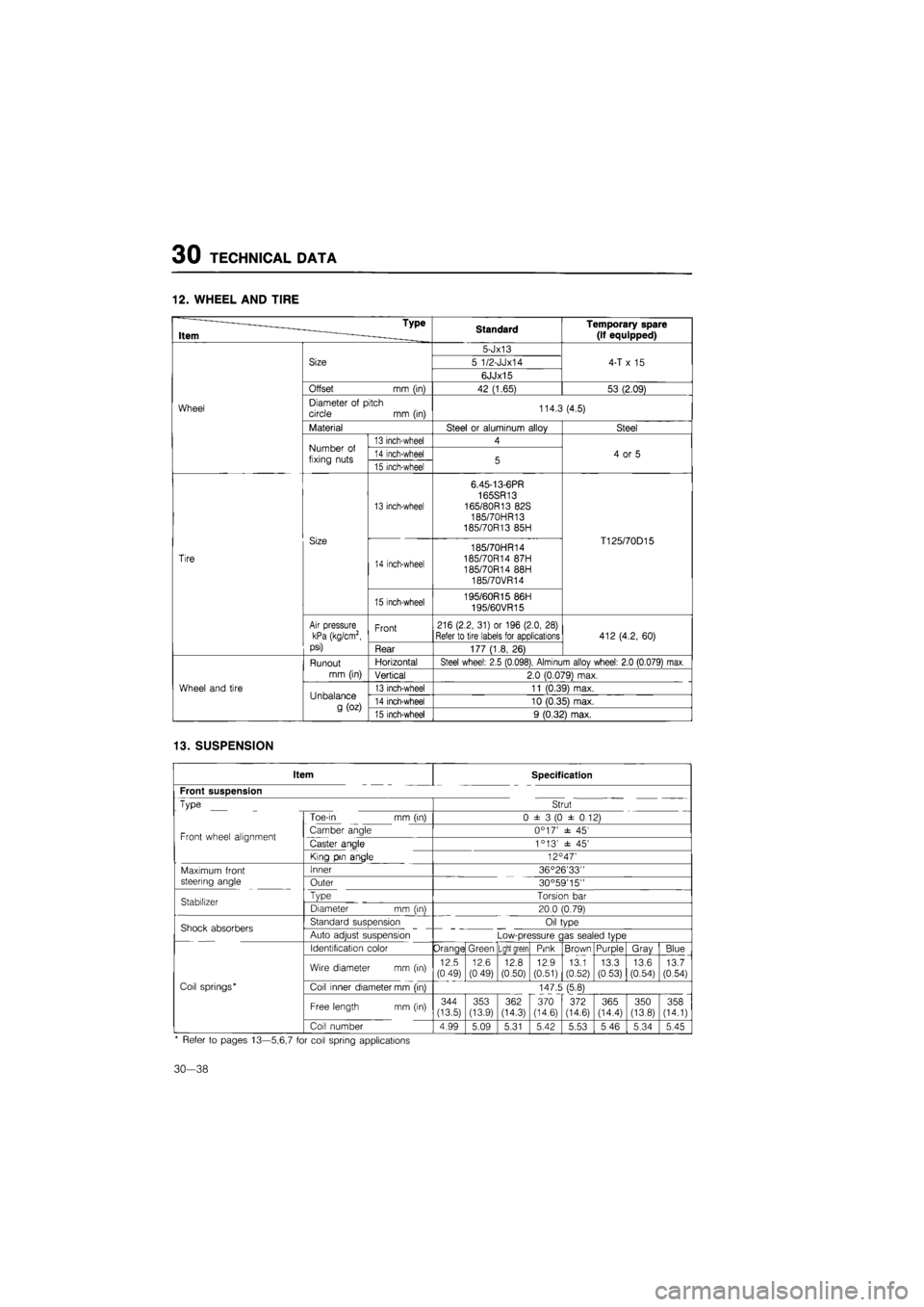
30 TECHNICAL DATA
12. WHEEL AND TIRE
* ~— - Type
Item ~ ———_____ Standard Temporary spare
(if equipped)
Wheel
Size
5-Jx13
4-T
x 15
Wheel
Size 5 1/2-JJx14 4-T
x 15
Wheel
Size
6JJx15
4-T
x 15
Wheel
Offset
mm (in)
42 (1.65) 53 (2.09)
Wheel Diameter
of
pitch circle
mm
(in) 114.3 (4.5) Wheel
Material Steel
or
aluminum alloy Steel
Wheel
Number
of
fixing nuts
13 inch-wheel 4
4
or 5
Wheel
Number
of
fixing nuts 14 inch-wheel 5 4
or 5
Wheel
Number
of
fixing nuts 15 inch-wheel 5 4
or 5
Tire
Size
13 inch-wheel
6.45-13-6PR 165SR13 165/80R13 82S
185/70HR13 185/70R13 85H
T125/70D15
Tire
Size
14 inch-wheel
185/70HR14 185/70R14 87H 185/70R14 88H 185/70VR14
T125/70D15
Tire
Size
15 inch-wheel 195/60R15 86H 195/60VR15
T125/70D15
Tire
Air pressure kPa (kg/cm2, psi)
Front 216 (2.2, 31)
or
196 (2.0, 28)
Refer to tire labels for applications 412 (4.2, 60)
Tire
Air pressure kPa (kg/cm2, psi) Rear 177 (1.8,
26)
412 (4.2, 60)
Wheel and tire
Runout
mm (in)
Horizontal Steel wheel: 2.5 (0.098), Alminum allov wheel: 2.0 (0.079) max.
Wheel and tire
Runout
mm (in) Vertical 2.0 (0.079) max.
Wheel and tire Unbalance
g
(oz)
13 inch-wheel 11 (0.39) max. Wheel and tire Unbalance
g
(oz) 14 inch-wheel 10 (0.35) max.
Wheel and tire Unbalance
g
(oz) 15 inch-wheel 9 (0.32) max.
13. SUSPENSION
Item Specification
Front suspension
Type Strut
Toe-in
mm
(in) 0 ±
3 (0
±
0
12)
Front wheel alignment Camber angle 0°17' ±
45'
Front wheel alignment Caster angle 1 °13' ±
45'
King pin angle 12C 47'
Maximum front Inner 36°26'33"
steering angle Outer 30°59'15"
Stabilizer Type Torsion
bar
Stabilizer Diameter
mm (in)
20.0 (0.79)
Shock absorbers Standard suspension Oil type Shock absorbers Auto adjust suspension Low-pressure gas sealed type
Identification color Orange Green Light green Pink Brown Purple Gray Blue
Wire diameter
mm (in)
12.5
(0.49)
12.6
(0.49) 12.8 (0.50) 12.9 (0.51) 13.1 (0.52) 13.3 (0.53) 13.6 (0.54) 13.7 (0.54)
Coil springs* Coil inner diameter mm (in) 147.5 (5.8)
Free length
mm
(in) 344 (13.5)
CO <35
362
(14.3)
370
(14.6)
372 (14.6) 365 (14.4) 350 (13.8) 358 (14.1)
Coil number 4.99 5.09 5.31 5.42 5.53 5.46 5.34 5.45
* Refer
to
pages 13—5,6,7
for
coil spring applications
30-38
Page 1863 of 1865
SPECIAL TOOLS 40
TOOL NUMBER
& DESCRIPTION PRIORITY ILLUSTRATION
49 G032 3A0
Repair set, power steering (ESPS)
A
0 "
'
= 1 6 J
•Dn
0 O
•ujQ
BRAKE
TOOL NUMBER
& DESCRIPTION PRIORITY ILLUSTRATION
49 0259 770B
Wrench, flare
nut
A
49 0221 600C
Expand tool,
disc brake
B
49 FA18 602
Wrench disc,
brake piston B
SUSPENSION
TOOL NUMBER & DESCRIPTION PRIORITY ILLUSTRATION
49 G028 2A0
Replacer lower arm bush (4WS)
A
49 G034 2A0
Replacer lower arm bush A
-
Q
0a0(D
TOOL NUMBER & DESCRIPTION PRIORITY ILLUSTRATION
— — —
TOOL NUMBER & DESCRIPTION PRIORITY ILLUSTRATION
49 B043 002
Bearing installer (Rear disc)
A
49 F043
001
Adjust gauge A
49 B043 001
Adjust gauge
(FE
DOHC-R.H.D)
—
iP
TOOL NUMBER
& DESCRIPTION PRIORITY ILLUSTRATION
49 U034 2A0
Replacer rubber bush (4WS)
A
49 G034
1
AO
Coil spring
compressor
A
40—9