1987 MAZDA 626 inflation pressure
[x] Cancel search: inflation pressurePage 888 of 1865

7B TROUBLESHOOTING (G4A-EL)
STEP 2 (PRELIMINARY INSPECTION)
In this step, the fundamental points related to the automatic transaxle are checked. These points must
be kept in the correct condition at all times in order to assure proper operation of the automatic transaxle.
1. Automatic Transmission Fluid (ATF)
Check ATF level and condition. (Refer to page 7B—71)
2. Selector Lever
Check selector lever position and adjust if necessary. (Refer to page 7B—72)
76G07B-022
3. Throttle cable
(1) Check the inner and outer cable for damage.
(2) Make sure that the accelerator operates
smoothly.
76G07B-023
4. Idle Speed
Check idle speed. (Refer to Section 4B)
5. Tire Inflation Pressure
Check tire inflation pressure. (Refer to Section 12)
76G07B-024
6. Inhibitor Switch
Check the inhibitor switch for operation. (Refer to
page 7B—65)
76G07B-025
7B-22
Page 912 of 1865

7B TROUBLESHOOTING (G4A-HL)
5. Throttle Cable
(1) Check the inner and outer cable for damage.
(2) Make sure that the accelerator operates
smoothly.
76g07b-046
6. Idle Speed
Check idle speed. (Refer to Section 4A)
7. Tire Inflation Pressure
Check tire inflation pressure. (Refer to Section 12)
8. Ignition Timing
Check ignition timing. (Refer to Section 5)
7B-46
Page 1122 of 1865
7C TROUBLESHOOTING
TROUBLESHOOTING
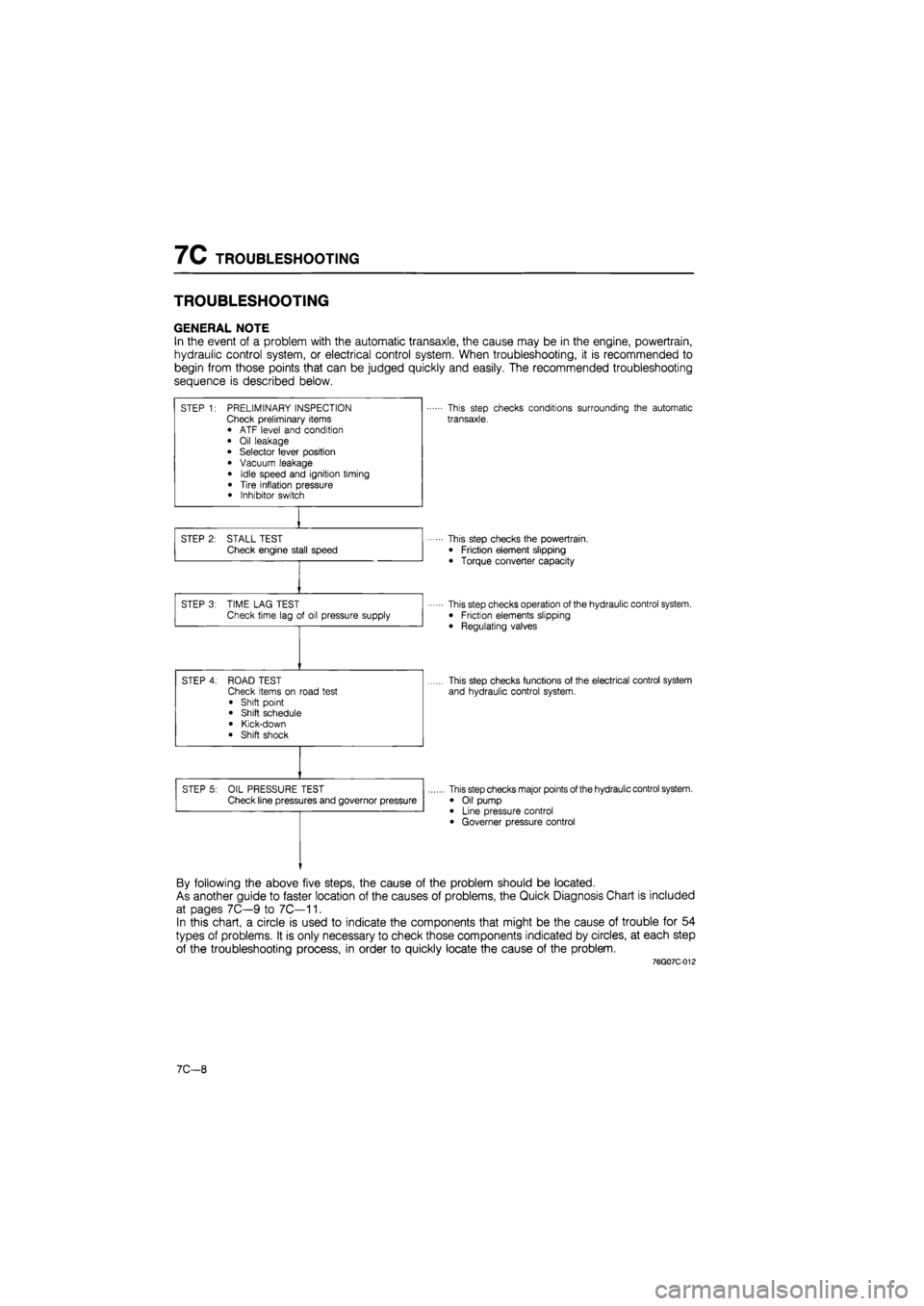
GENERAL NOTE
In the event of a problem with the automatic transaxle, the cause may be in the engine, powertrain,
hydraulic control system, or electrical control system. When troubleshooting, it is recommended to
begin from those points that can be judged quickly and easily. The recommended troubleshooting
sequence is described below.
STEP 1: PRELIMINARY INSPECTION Check preliminary items • ATF level and condition
• Oil leakage • Selector lever position
• Vacuum leakage
• Idle speed and ignition timing
• Tire inflation pressure • Inhibitor switch
This step checks conditions surrounding the automatic
transaxle.
STEP 2: STALL TEST Check engine stall speed This step checks the powertrain.
• Friction element slipping
• Torque converter capacity
STEP 3: TIME LAG TEST Check time lag of oil pressure supply This step checks operation of the hydraulic control system. • Friction elements slipping
• Regulating valves
STEP 4: ROAD TEST Check items on road test
• Shift point • Shift schedule
• Kick-down • Shift shock
This step checks functions of the electrical control system
and hydraulic control system.
STEP 5: OIL PRESSURE TEST Check line pressures and governor pressure This step checks major points of the hydraulic control system.
• Oil pump • Line pressure control • Governer pressure control
By following the above five steps, the cause of the problem should be located.
As another guide to faster location of the causes of problems, the Quick Diagnosis Chart is included
at pages 7C—9 to 7C—11.
In this chart, a circle is used to indicate the components that might be the cause of trouble for 54
types of problems. It is only necessary to check those components indicated by circles, at each step
of the troubleshooting process, in order to quickly locate the cause of the problem.
76G07C-012
7C—8
Page 1127 of 1865
TROUBLESHOOTING 7C
76G07C-020
76G07C-021
76G07C-022
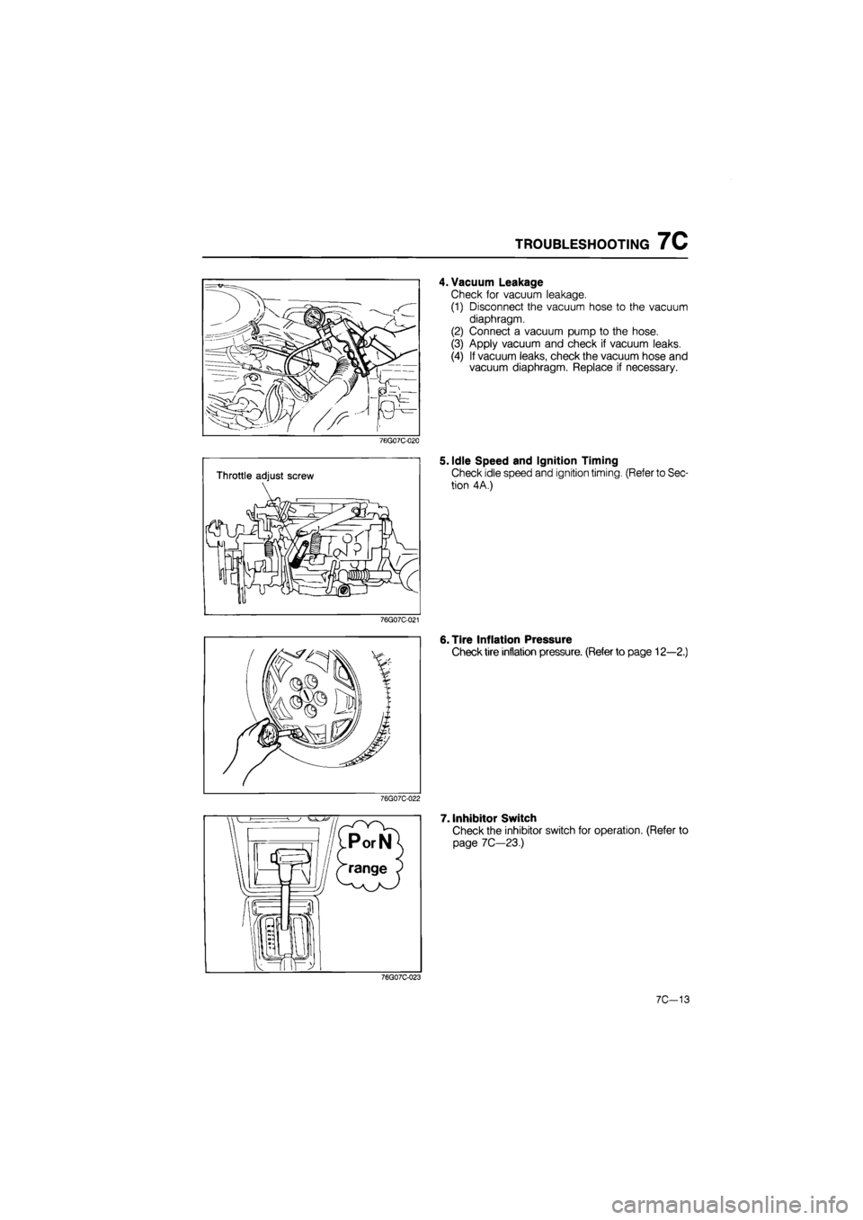
4. Vacuum Leakage
Check for vacuum leakage.
(1) Disconnect the vacuum hose to the vacuum
diaphragm.
(2) Connect a vacuum pump to the hose.
(3) Apply vacuum and check if vacuum leaks.
(4) If vacuum leaks, check the vacuum hose and
vacuum diaphragm. Replace if necessary.
5. Idle Speed and Ignition Timing
Check idle speed and ignition timing. (Refer to Sec-
tion 4A.)
6. Tire Inflation Pressure
Check tire inflation pressure. (Refer to page 12—2.)
7. Inhibitor Switch
Check the inhibitor switch for operation. (Refer to
page 7C—23.)
76G07C-023
7C-13
Page 1494 of 1865
WHEELS AND TIRES 1 2
86U12X-004
\k
y
i jYj
/ <4/
/ v Wear platform
Wear indicators
86U12X-005
(a) (b)
Shoulder wear Center wear
(c)
Feathered edge
(d)
*f tftiit t
Toe-in or toe-out wear Uneven wear
WHEELS AND TIRES
INSPECTION AND ADJUSTMENTS
Check the following, and adjust or replace as
necessary.
1. Air pressure
Check the air pressure of all tires, including the
spare tire, with an air pressure gauge.
(Refer to page 12—2.)
Caution
The air pressure must be measured when the
tire is cold.
2. Tire wear
Specifications
Remaining tread
Ordinary tires: 1.6 mm (0.063 in) min.
(Tire should be replaced if wear indicators are
exposed.)
Snow tires: 50% of tread
(Tire should be replaced if wear indicators are
exposed.)
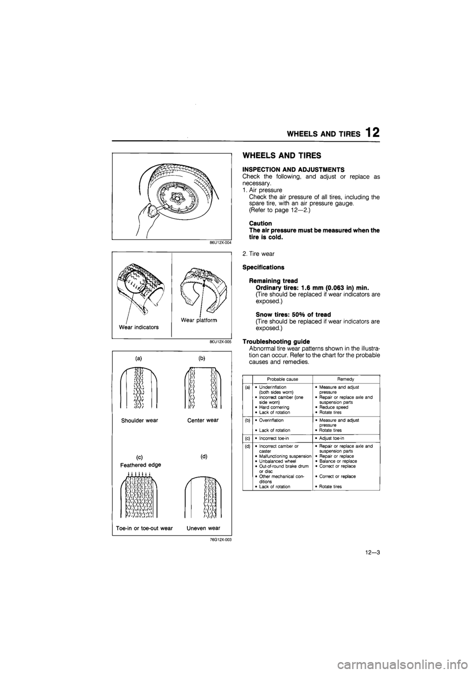
Troubleshooting guide
Abnormal tire wear patterns shown in the illustra-
tion can occur. Refer to the chart for the probable
causes and remedies.
Probable cause Remedy
(a) • Underinflation (both sides worn) • Incorrect camber (one side worn) • Hard cornering • Lack of rotation
• Measure and adjust pressure • Repair or replace axle and suspension parts • Reduce speed • Rotate tires
(b) • Overinflation
• Lack of rotation
• Measure and adjust pressure • Rotate tires
(c) • Incorrect toe-in • Adjust toe-in
(d) • Incorrect camber or caster • Malfunctioning suspension • Unbalanced wheel • Out-of-round brake drum or disc • Other mechanical con-ditions • Lack of rotation
• Repair or replace axle and suspension parts • Repair or replace • Balance or replace • Correct or replace
• Correct or replace
• Rotate tires
76G12X-003
12-3
Page 1547 of 1865
1 3 FRONT WHEEL ALIGNMENT
FRONT WHEEL ALIGNMENT
86U13X-108
69G10X-031
Pre-inspection
1. Check the tire inflation and bring to the recom-
mended pressure.
2. Inspect the front wheel bearing play and correct,
it if necessary.
3. Inspect the wheel and tire runout.
4. Inspect the ball joints and steering linkage for any
excessive looseness.
5. The vehicle must be on level ground and have no
luggage or passenger load.
6. The difference in height between the left and right
sides from the center of the wheel to the fender
brim must be within 10 mm (0.39 in).
Caution
a) Front and rear wheel alignment should be
checked simultaneously. If adjustment is
made to either the front or rear wheels,
recheck the alignment, particularly toe-in,
on all other wheels.
b) Check and adjust the steering angle trans-
fer shaft after adjusting the front wheel
alignment. (Refer to Section 10)
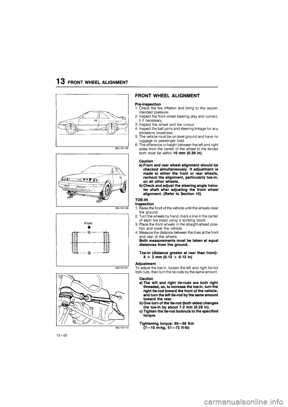
TOE-IN
Inspection
1. Raise the front of the vehicle until the wheels clear
the ground.
2. Turn the wheels by hand, mark a line in the center
of each tire tread using a scribing block.
3. Place the front wheels in the straight-ahead posi-
tion and lower the vehicle.
4. Measure the distance between the lines at the front
and rear of the wheels.
Both measurements must be taken at equal
distances from the ground.
Toe-in (distance greater at rear than front):
3 ± 3 mm (0.12 ± 0.12 in)
Adjustment
To adjust the toe-in, loosen the left and right tie-rod
lock nuts, then turn the tie-rods by the same amount.
Caution
a) The left and right tie-rods are both right
threaded, so, to increase the toe-in, turn the
right tie-rod toward the front of the vehicle,
and turn the left tie-rod by the same amount
toward the rear.
b) One turn of the tie-rod (both sides) changes
the toe-in by about 7.2 mm (0.28 in).
c) Tighten the tie-rod locknuts to the specified
torque.
Tightening torque: 69—98 N-m
(7—10 m-kg, 51—72 ft-lb) 86U13X-110
13-50
Page 1549 of 1865
13 REAR WHEEL ALIGNMENT
76G13X-033
86U13X-116
86U13X-117
86U13X-116
13-52
REAR WHEEL ALIGNMENT
PRE-INSPECTION
1. Check the tire inflation and bring to the recom-
mended pressure.
2. Inspect the wheel and tire runout.
3. The vehicle must be on level ground and have no
luggage or passenger load.
4. Check that the suspension is correctly adjusted.
5. The difference in height between the left and right
sides from the center of the wheel to the fender
rim should be within 10 mm (0.39 in).
Caution
a) Front and rear wheel alignments should be
checked simultaneously. If adjustment is
made to either the front or rear wheels,
recheck the alignment, particularly toe-in,
on all other wheels.
b) Check and adjust the steering angle trans-
fer shaft after adjusting the rear wheel align-
ment. (Refer to Section 10.)
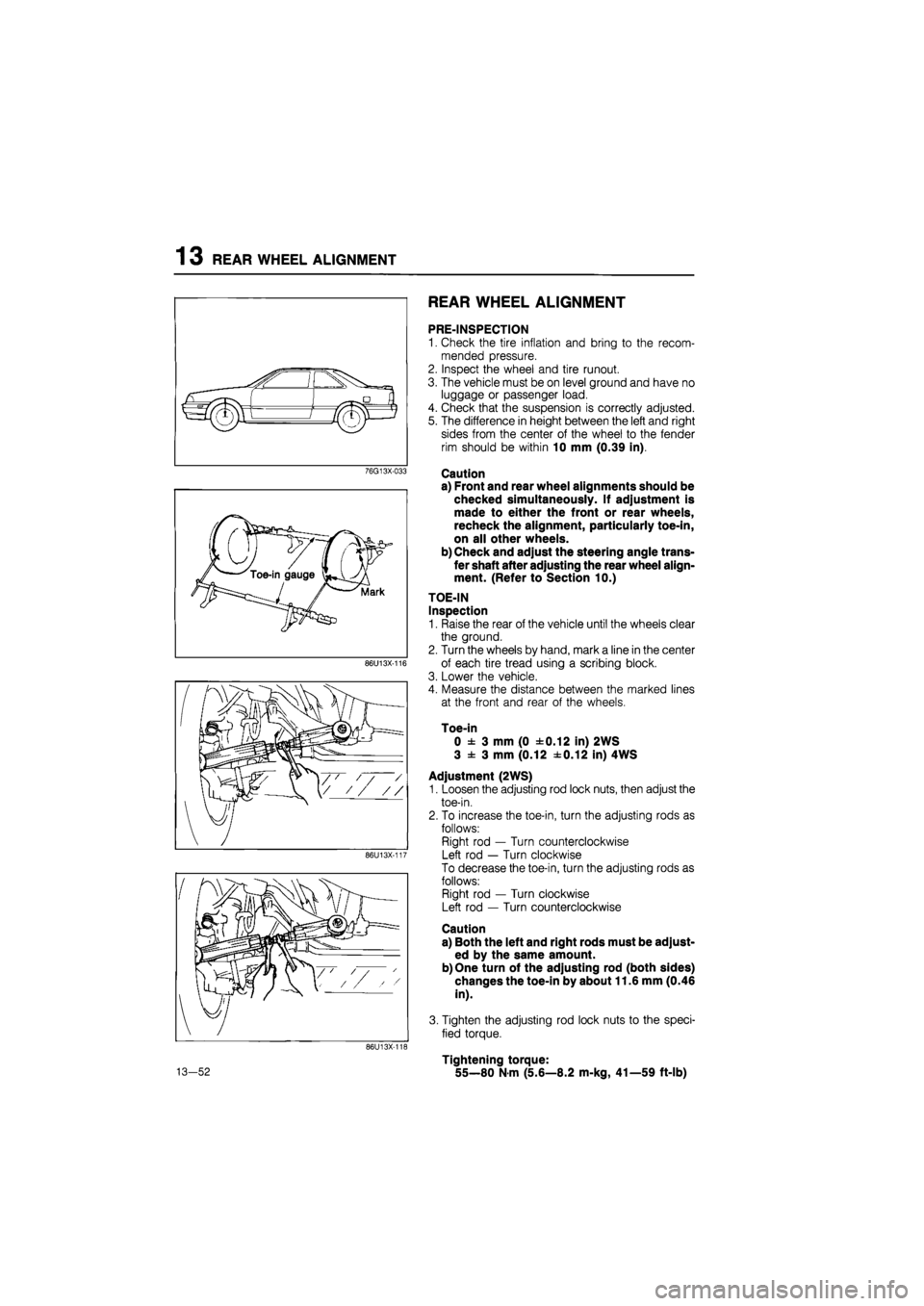
TOE-IN
Inspection
1. Raise the rear of the vehicle until the wheels clear
the ground.
2. Turn the wheels by hand, mark a line in the center
of each tire tread using a scribing block.
3. Lower the vehicle.
4. Measure the distance between the marked lines
at the front and rear of the wheels.
Toe-in
0 ± 3 mm (0 ±0.12 in) 2WS
3 ± 3 mm (0.12 ±0.12 in) 4WS
Adjustment (2WS)
1. Loosen the adjusting rod lock nuts, then adjust the
toe-in.
2. To increase the toe-in, turn the adjusting rods as
follows:
Right rod — Turn counterclockwise
Left rod — Turn clockwise
To decrease the toe-in, turn the adjusting rods as
follows:
Right rod — Turn clockwise
Left rod — Turn counterclockwise
Caution
a) Both the left and right rods must be adjust-
ed by the same amount.
b) One turn of the adjusting rod (both sides)
changes the toe-in by about 11.6 mm (0.46
in).
3. Tighten the adjusting rod lock nuts to the speci-
fied torque.
Tightening torque:
55—80 N-m (5.6—8.2 m-kg, 41—59 ft-lb)