Page 32 of 1865
0 1 ro o
interval
Procedure & item
Number of Months or km, whichever corns first
©1 ©2 ©3 ©4 Service data and inspection point Page
interval
Procedure & item
Months — 6 12 18 24 30 36 42 48 ©1 ©2 ©3 ©4 Service data and inspection point Page
interval
Procedure & item
x 1000 Km
1 10 20 30 40 50 60 70 80 ©1 ©2 ©3 ©4 Service data and inspection point Page
interval
Procedure & item
Miles x 1000
0.6 6 12 18 24 30 36 42 48
©1 ©2 ©3 ©4 Service data and inspection point Page
Front suspension ball joints I I O o o o • Damage, looseness and grease
leakage 13—20
Drive shaft dust boots I I I I o o 0 o • Cracking and damage 9-32 9—36
Bolts and nuts on chassis and body T T T T T o 0 o o —
Page 500 of 1865
4B IDLE-UP SYSTEM
AIR VALVE
Pre-inspection
1. Start the engine and run it at idle.
2. Pinch the bypass air hose and check that the en-
gine rpm drops.
When engine still cool RPM reduced
After warming-up RPM drop within
200 rpm
3. If the speed is not reduced when cold, check the
air valve, or check for vacuum leaks at the bypass
air hose.
4. If the speed drop is more than 200 rpm when
warm, check the air valve and current to the valve.
Inspection of Terminal Voltage
1. Disconnect the connector from the valve.
2. Remove the rubber boot from the connector.
3. Start the engine and run it at idle.
4. Check that there is battery voltage at terminal (WY),
using a voltmeter.
5. If not correct, check the circuit opening relay and
wiring harness.
76G04B-046
Inspection of Air Valve
1. Check the valve for operation.
Temperature 20°C (68°F) Valve open
(When engine cool)
After warming-up Valve closed
2. Replace valve if faulty.
76G04B-047
4B—38 expert22 Arm http://rutracker.org
Page 557 of 1865

CONTROL SYSTEM 4B
76G04B-114
c jr y—
D
'
CO CO
76G04B-115
76U04A-018
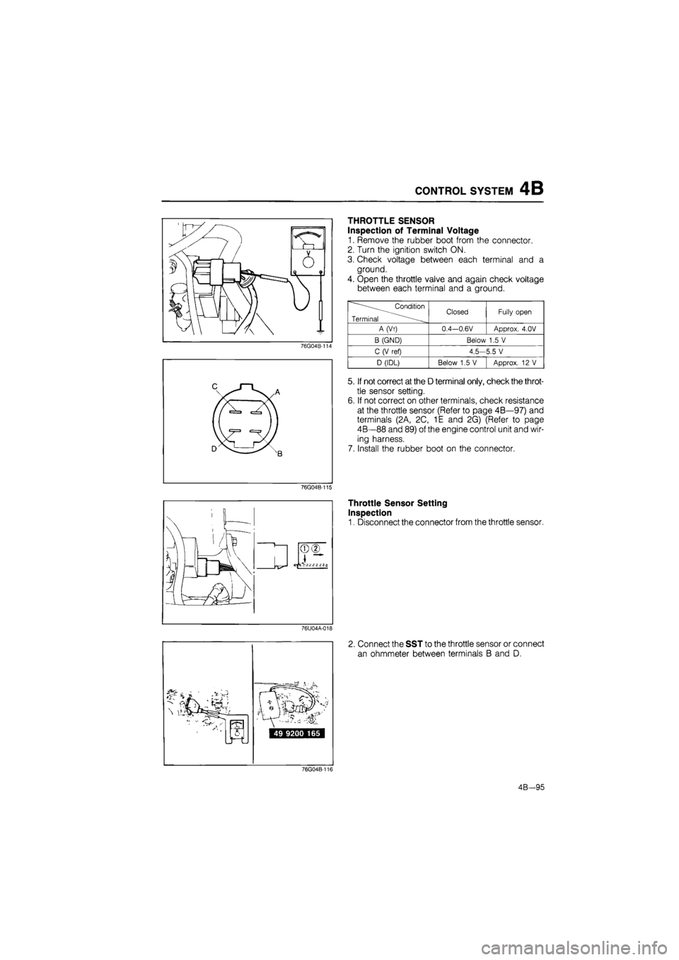
THROTTLE SENSOR
Inspection of Terminal Voltage
1. Remove the rubber boot from the connector.
2. Turn the ignition switch ON.
3. Check voltage between each terminal and a
ground.
4. Open the throttle valve and again check voltage
between each terminal and a ground.
Condition
Terminal Closed Fully open
A(Vt) 0.4—0.6V Approx. 4.0V
B (GND) Below 1.5 V
C (V ref) 4.5—5.5 V
D (IDL) Below 1.5 V Approx. 12 V
5. If not correct at the D terminal only, check the throt-
tle sensor setting.
6. If not correct on other terminals, check resistance
at the throttle sensor (Refer to page 4B—97) and
terminals (2A, 2C, 1E and 2G) (Refer to page
4B—88 and 89) of the engine control unit and wir-
ing harness.
7. Install the rubber boot on the connector.
Throttle Sensor Setting
Inspection
1. Disconnect the connector from the throttle sensor.
2. Connect the SST to the throttle sensor or connect
an ohmmeter between terminals B and D.
76G04B-116
4B-95
Page 664 of 1865
CONTROL SYSTEM 4C
AIR FLOW SENSOR
Visual Inspection
1. Remove the air hose.
2. Check the air flow sensor visually for the following:
a) Torn protection net (air cleaner side)
76G04C-183
b) Restricted protection net
76G04C-184
Output Voltage Inspection
1. Remove the rubber boot from the air flow sensor
connector.
2. Check terminal voltage with a voltmeter.
——^.Condition Terminal — ... Ign. switch;ON Engine running
A (Idle mixture) 0—5V
B (Power supply) Approx. 12V
C (Burn-off) OV
D (Air flow mass) 1.0-1,6V I 1.7V-5V
E (Ground) OV
F (Ground) 0V
6. If not correct, check the wiring harness for an open
or short circuit
7. If the wiring harness is OK, replace the air flow
sensor.
76G04C-185
4C-103
Page 669 of 1865
4C CONTROL SYSTEM
Check connector: Green (6 pin)
cable
49 H018 9A1
Inspection of Sensitivity
1. Warm up the engine to the normal operating tem-
perature and run it at idle.
2. Connect the SST to the check connector.
Note
Digital code checker (49 G018 9A0) can be
used.
76G04C-213
Increase the engine speed to between 2,000 and
3,000 rpm, and check that the monitor lamp flash-
es for 10 seconds.
Monitor lamp: Flashes ON and OFF
more than 8 times/10 sec
86U04A-208
A B C D
/llkw^ - ®
I « ^
76G04C-201
4C—108
DISTRIBUTOR
On-vehicle Inspection
1. Remove the rubber boot from the distributor con-
nector.
2. Run the engine at idle.
3. Check terminal voltage with a voltmeter.
Terminal Voltaae
A (G signal) 1.0—2.4
B (Ne sianaB 1.8—2.2
C (Power supply) Approx. 12V
D (Ground) OV
4. If not correct, check the wiring harness for an open
or short circuit, then check the distributor for G sig-
nal or Ne signal.
Page 670 of 1865

CONTROL SYSTEM 4C
76G04C-203
76G04C-204
76G04C-205
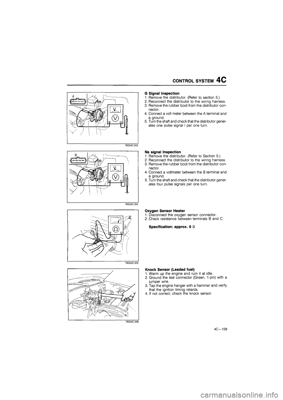
G Signal Inspection
1. Remove the distributor. (Refer to section 5.)
2. Reconnect the distributor to the wiring harness.
3. Remove the rubber boot from the distributor con-
nector.
4. Connect a volt meter between the A terminal and
a ground.
5. Turn the shaft and check that the distributor gener-
ates one pulse signal I per one turn.
Ne signal Inspection
1. Remove the distributor. (Refer to Section 5.)
2. Reconnect the distributor to the wiring harness.
3. Remove the rubber boot from the distributor con-
nector.
4. Connect a voltmeter between the B terminal and
a ground.
5. Turn the shaft and check that the distributor gener-
ates four pulse signals per one turn.
Oxygen Sensor Heater
1. Disconnect the oxygen sensor connector.
2. Check resistance between terminals B and C.
Specification: approx. 6 Q
Knock Sensor (Leaded fuel)
1. Warm up the engine and rum it at idle.
2. Ground the test connector (Green, 1-pin) with a
jumper wire.
3. Tap the engine hanger with a hammer and verify
that the ignition timing retards.
4. If not correct, check the knock sensor.
76G04C-206
4C-109
Page 715 of 1865

SPARK PLUG 5
Slow Charge
1. Stop the engine
2. Turn all the accessories off.
3. Remove the negative battery cable.
4. Perform a slow charge (3.5A to 4.5A).
5. Add distilled water if necessary while charging.
6. Charge once more if the specific gravity is under
fully charged gravity.
4BG05X-010
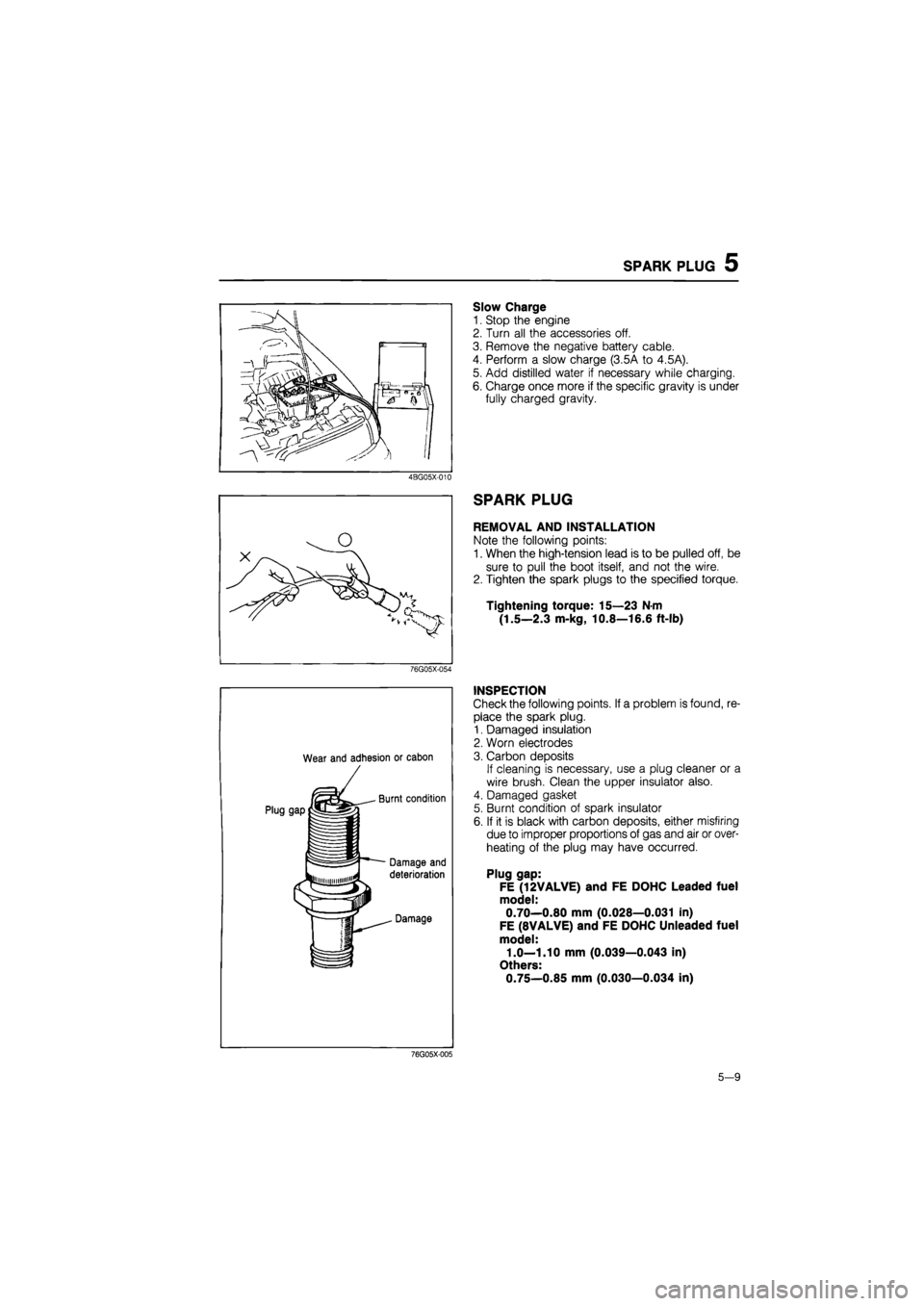
SPARK PLUG
REMOVAL AND INSTALLATION
Note the following points:
1. When the high-tension lead is to be pulled off, be
sure to pull the boot itself, and not the wire.
2. Tighten the spark plugs to the specified torque.
Tightening torque: 15—23 N-m
(1.5—2.3 m-kg, 10.8—16.6 ft-lb)
76G05X-054
Wear and adhesion or cabon
INSPECTION
Check the following points. If a problem is found, re-
place the spark plug.
1. Damaged insulation
2. Worn electrodes
3. Carbon deposits
If cleaning is necessary, use a plug cleaner or a
wire brush. Clean the upper insulator also.
4. Damaged gasket
5. Burnt condition of spark insulator
6. If it is black with carbon deposits, either misfiring
due to improper proportions of gas and air or over-
heating of the plug may have occurred.
Plug gap:
FE (12VALVE) and FE DOHC Leaded fuel
model:
0.70—0.80 mm (0.028—0.031 in)
FE (8VALVE) and FE DOHC Unleaded fuel
model:
1.0—1.10 mm (0.039—0.043 in)
Others:
0.75—0.85 mm (0.030—0.034 in)
76G05X-005
5-9
Page 798 of 1865
6 CLUTCH RELEASE CYLINDER
REMOVAL
1. Disconnect the clutch pipe, with the SST.
Note
Plug the pipe in order to prevent fluid from
leaking.
86U06X-020
2. Remove the installation bolts.
3. Remove the release cylinder.
86U06X-021
DISASSEMBLY
Components
6—9 N»m (60—90 em-kg, 52-78 In-lb)
1. Boot
2. Push rod
3. Piston.and pis-
ton cup
4. Return spring
5. Bleeder cap
6. Bleeder screw
7. Steel ball
8. Cylinder body
76G06X-022
6-12