1987 MAZDA 626 height
[x] Cancel search: heightPage 14 of 1865

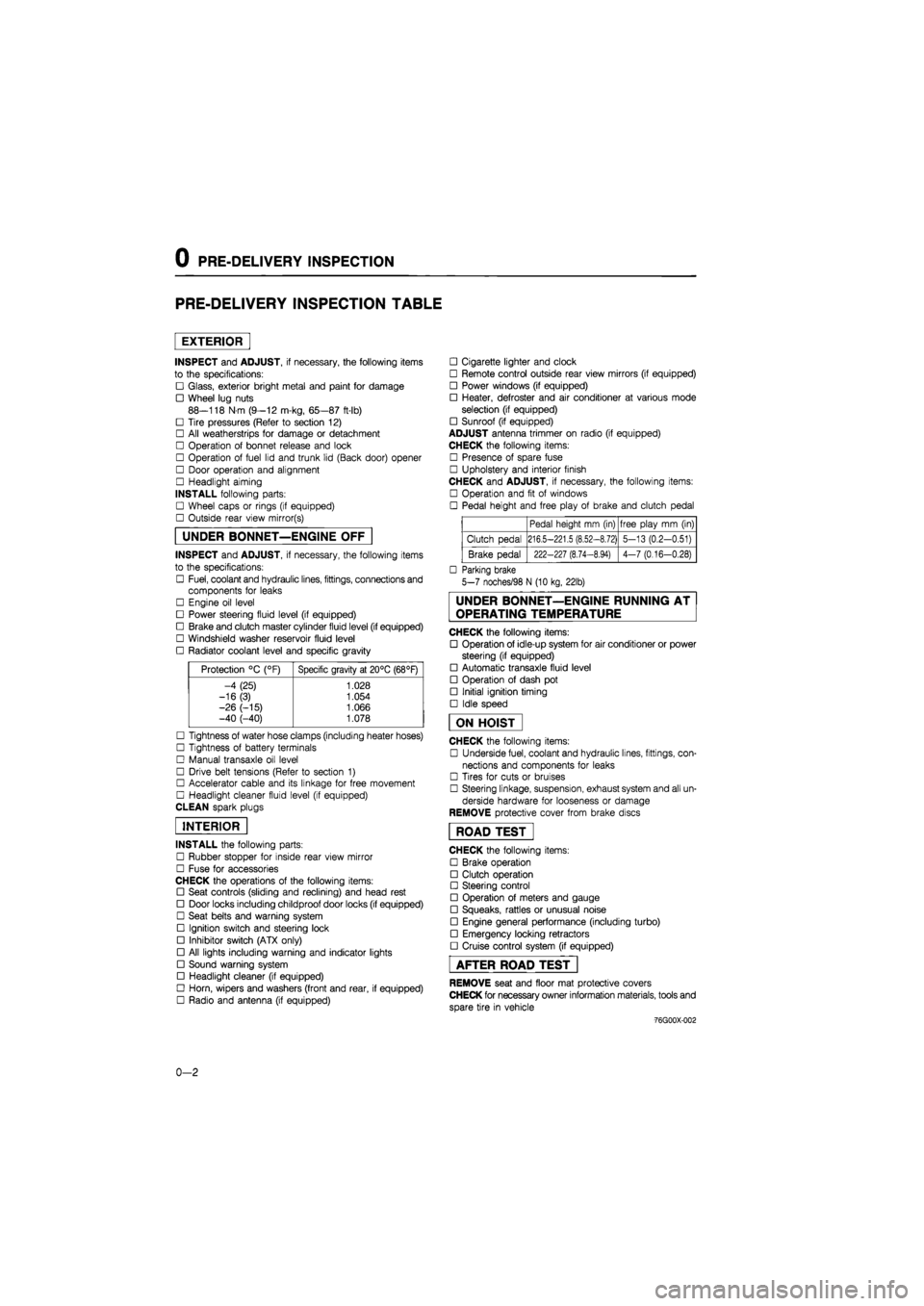
0 PRE-DELIVERY INSPECTION
PRE-DELIVERY INSPECTION TABLE
EXTERIOR
INSPECT and ADJUST, if necessary, the following items
to the specifications:
• Glass, exterior bright metal and paint for damage
• Wheel lug nuts
88—118 N m (9—12 m-kg, 65—87 ft-lb)
• Tire pressures (Refer to section 12)
• All weatherstrips for damage or detachment
• Operation of bonnet release and lock
• Operation of fuel lid and trunk lid (Back door) opener
• Door operation and alignment
• Headlight aiming
INSTALL following parts:
• Wheel caps or rings (if equipped)
• Outside rear view mirror(s)
UNDER BONNET—ENGINE OFF
INSPECT and ADJUST, if necessary, the following items
to the specifications:
• Fuel, coolant and hydraulic lines, fittings, connections and
components for leaks
• Engine oil level
• Power steering fluid level (if equipped)
• Brake and clutch master cylinder fluid level (if equipped)
• Windshield washer reservoir fluid level
• Radiator coolant level and specific gravity
Protection °C (°F) Specific gravity at 20°C (68°F)
-4 (25) 1.028
-16(3) 1.054
-26 (-15) 1.066 -40 (-40) 1.078
• Tightness of water hose clamps (including heater hoses)
• Tightness of battery terminals
• Manual transaxle oil level
• Drive belt tensions (Refer to section 1)
• Accelerator cable and its linkage for free movement
• Headlight cleaner fluid level (if equipped)
CLEAN spark plugs
INTERIOR
INSTALL the following parts:
• Rubber stopper for inside rear view mirror
• Fuse for accessories
CHECK the operations of the following items:
• Seat controls (sliding and reclining) and head rest
• Door locks including childproof door locks (if equipped)
• Seat belts and warning system
• Ignition switch and steering lock
• Inhibitor switch (ATX only)
• All lights including warning and indicator lights
• Sound warning system
• Headlight cleaner (if equipped)
• Horn, wipers and washers (front and rear, if equipped)
• Radio and antenna (if equipped)
• Cigarette lighter and clock
• Remote control outside rear view mirrors (if equipped)
• Power windows (if equipped)
• Heater, defroster and air conditioner at various mode
selection (if equipped)
• Sunroof (if equipped)
ADJUST antenna trimmer on radio (if equipped)
CHECK the following items:
• Presence of spare fuse
• Upholstery and interior finish
CHECK and ADJUST, if necessary, the following items:
• Operation and fit of windows
• Pedal height and free play of brake and clutch pedal
Pedal height mm (in) free play mm (in)
Clutch pedal 216.5-221.5 (8.52-8.72) 5-13 (0.2-0.51)
Brake pedal 222-227 (8.74-8.94) 4-7 (0.16-0.28)
• Parking brake
5-7 noches/98 N (10 kg, 22lb)
UNDER BONNET—ENGINE RUNNING AT
OPERATING TEMPERATURE
CHECK the following items:
• Operation of idle-up system for air conditioner or power
steering (if equipped)
• Automatic transaxle fluid level
• Operation of dash pot
• Initial ignition timing
• Idle speed
ON HOIST
CHECK the following items:
• Underside fuel, coolant and hydraulic lines, fittings, con-
nections and components for leaks
• Tires for cuts or bruises
• Steering linkage, suspension, exhaust system and all un-
derside hardware for looseness or damage
REMOVE protective cover from brake discs
ROAD TEST"
CHECK the following items:
• Brake operation
• Clutch operation
• Steering control
• Operation of meters and gauge
• Squeaks, rattles or unusual noise
• Engine general performance (including turbo)
• Emergency locking retractors
• Cruise control system (if equipped)
AFTER ROAD TEST
REMOVE seat and floor mat protective covers
CHECK for necessary owner information materials, tools and
spare tire in vehicle
-76G00X-002
0-2
Page 16 of 1865

0 1 Interval
Procedure & item
Number of Months or km, whichever corns first
©1 ©2 ©3 ©4 Service data and inspection point Page
Interval
Procedure & item
Months — 6 12 18 24 30 36 42 48 ©1 ©2 ©3 ©4 Service data and inspection point Page
Interval
Procedure & item
x 1000 Km 1 10 20 30 40 50 60 70 80 ©1 ©2 ©3 ©4 Service data and inspection point Page
Interval
Procedure & item
Miles x
1000 0.6 6 12 18 24 30 36 42 48
©1 ©2 ©3 ©4 Service data and inspection point Page
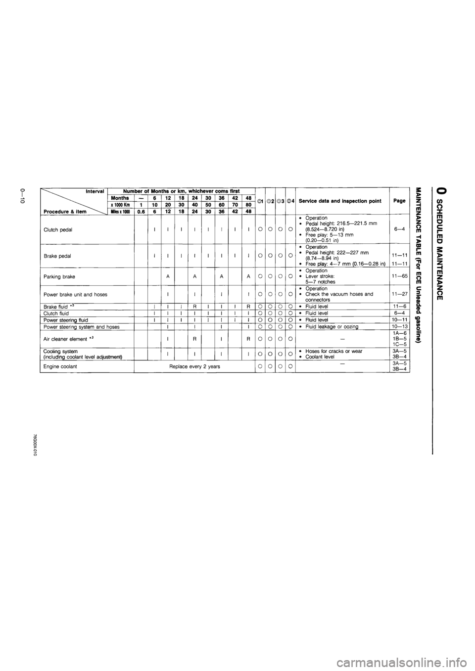
Clutch pedal I 1 I I I I I I O O o o
• Operation
• Pedal height: 216.5—221.5 mm
(8.524—8.720 in) • Free play: 5—13 mm (0.20-0.51 in)
6-4
Brake pedal I 1 I I I I I I O o o o
• Operation
• Pedal height: 222—227 mm (8.74-8.94 in)
• Free play: 4—7 mm (0.16—0.28 in)
11—11
11—11
Parking brake A A A A o o o o
• Operation
• Lever stroke:
5—7 notches
11—65
Power brake unit and hoses 1 I I I o o o o • Operation • Check the vacuum hoses and con-nectors
11—27
Brake fluid " I 1 I R I I I R o o o o • Fluid level 11-6
Clutch fluid I 1 I I I I I I o o o o • Fluid level 6—4
Power steering fluid I 1 I I I I I I
I
o
o"
o
o
o o • Fluid level 10—11
Power steering system and hoses 1 I I
I I
I
o
o"
o
o o o • Fluid leakage or oozing 10—13
Air cleaner element *3 1 R I R —
1A—6 1B—5 1C—5
Choke system 1 I I o o X X
• Carburetor linkage • Choke diaphragm • Choke valve clearance
• Choke Unloader system
4A-26 4A—34 4A—34 4A—33
Cooling system (including coolant level adjustment) 1 I I I o o o o • Hoses for cracks or wear
• Coolant level
3A—5 3B—4
Engine coolant Replace every 2 years o o o o -3A-5 3B-4
Page 22 of 1865

0
1
o
interval
Procedure & Item
Number of Months or km, whichever corns first
©1 ©2 ©3 ©4 Service data and inspection point Page
interval
Procedure & Item
Months — 6 12 18 24 30 36 42 48 ©1 ©2 ©3 ©4 Service data and inspection point Page
interval
Procedure & Item
x
1000 Km
1 10 20 30 40 50 60 70 80 ©1 ©2 ©3 ©4 Service data and inspection point Page
interval
Procedure & Item
Miles x 1000
0.6 6 12 18 24 30 36 42 48
©1 ©2 ©3 ©4 Service data and inspection point Page
Clutch pedal I I I I I I I I O o o o
• Operation
• Pedal height: 216.5—221.5 mm (8.524—8.720 in)
• Free play: 5—13 mm (0.20—0.51 in)
6-4
Brake pedal I I I I I I I I O o o o
• Operation • Pedal height: 222—227 mm (8.74—8.94 in)
• Free play: 4—7 mm (0.16—0.28 in)
11-11
11—11
Parking brake A A A A o o o o
• Operation • Lever stroke: 5—7 notches
11-65
Power brake unit and hoses I I I I o o o o
• Operation • Check the vacuum hoses and connectors
11—27
Brake fluid *5 I I I R I I I R 0 o o o • Fluid level 11—6
Clutch fluid I I I I I I I I o o o 0 • Fluid level 6-4
Power steering fluid I I I I I I I I o o o o • Fluid level 10—11
Power steering system and hoses I I I I 0 o o 0 • Fluid leakage or oozing 10—13
Air cleaner element *3 I R I R o o o o —
1 A—6 1B—5 1C-5
Cooling system (including coolant level adjustment) I I I I o o o o • Hoses for cracks or wear • Coolant level
3A—5
3B-4
Engine coolant Replace every 2 years 0 o 0 0 — 3A-5 3B—4
a> a o o X o o
Page 28 of 1865

0 1
CO
interval Number of Months or km, whichever corns first
Months — 6 12 18 24 30 36 42 48 ©1 ©2 ©3 ©4 Service data and inspection point Page x 1000 Km 1 10 20 30 40 50 60 70 80 ©1 ©2 ©3 ©4 Service data and inspection point Page
Procedure & item Miles x 1000 0.6 6 12 18 24 30 36 42 48
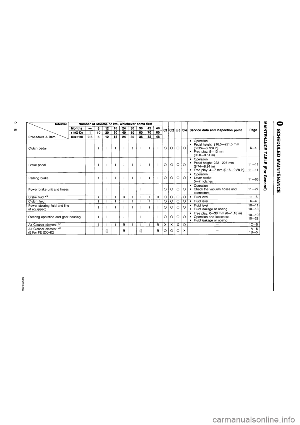
Clutch pedal I I I I I I I I O o o o
• Operation • Pedal height: 216.5—221.5 mm (8.524—8.720 in) • Free play: 5—13 mm (0.20—0.51 in)
6—4
Brake pedal I I I I I I I I o o o o
• Operation
• Pedal height: 222—227 mm (8.74—8.94 in)
• Free play: 4—7 mm (0.16—0.28 in)
11-11
11—11
Parking brake I I I I I I I I o o o o
• Operation • Lever stroke 5—7 notches 11-65
Power brake unit and hoses I I I I o o o o
• Operation • Check the vacuum hoses and connectors
11—27
Brake fluid *s I I I R I I I R o o o o • Fluid level 11-6
Clutch fluid I I I I I I I I o o o o • Fluid level 6-4
Power steering fluid and line (if equipped) I I I I I I I I o o o o • Fluid level • Fluid leakage or oozing
10—11
10—13
Steering operation and gear housing I I I I I o o o o
• Free play: 0—30 mm (0—1.18 in) • Operation and looseness • Fluid leakage or oozing
10—10
10-28
Air Cleaner element *3 I I I R I I I R X X X o — 1C—5
Air Cleaner element *3 (1) For FE (DOHC) (0 R (I) R o o o X — 1A—6
1B—5
Page 80 of 1865

INSPECTION AND REPAIR 1 A
INSPECTION AND REPAIR
1. Clean all parts, taking care to remove any gasket fragments, dirt, oil or grease, carbon, moisture
residue, or other foreign materials.
2. Inspect and repair must be performed in the order specified.
Caution
Be careful not to damage the joints or friction surfaces of aluminum alloy components (such
as the cylinder head or pistons).
86U01X-077
Cylinder Head
1. Inspect the cylinder head for damage, cracks, and
leakage of water or oil. Replace if necessary.
2. Measure the cylinder head distortion in the six
directions shown in the figure.
Distortion: 0.15 mm (0.006 in) max.
79G01C-106
If the cylinder head distortion exceeds specifica-
tion, grind the cylinder head surface.
If the cylinder head height is not within specifica-
tion, replace it.
Height:
91.95—92.05 mm (3.620—3.624 in)
Grinding limit: 0.20 mm (0.008 in) max.
Note
Before grinding the cylinder head, first check
the following. Replace if necessary.
• Sinking of valve seat
• Damage of manifold contact surface
• Camshaft oil clearance and end play
Measure the manifold contact surface distortion in
the six directions shown in the figure.
Distortion: 0.15 mm (0.006 in) max.
If distortion exceeds specification grind the surface
or replace the cylinder head.
79G01C-053
1A—48
Page 82 of 1865

INSPECTION AND REPAIR 1 A
86U01X-082
Valve guide
Cylinder head
76G01A-057
(2) Method No. 2
Measure the valve stem play at a point close
to the valve guide with the valve lifted slightly
off the valve seat.
Clearance
IN : 0.025—0.060 mm (0.0010—0.0024 in)
EX: 0.030—0.065 mm (0.0012—0.0026 in)
Maximum: 0.20 mm (0.0079 in)
7. If the clearance exceeds the maximum, replace the
valve and/or valve guide.
8. Check that the valve guide projection height
(dimension A in the figure). Replace if necessary.
Height:
19.8—20.3 mm (0.780—0.799 in)... 12-valve
19.1—19.6 mm (0.752—0.772 in)...8-valve
Replacement of valve guide
Note
Although the shapes of the intake and exhaust
valve guides are different, use the exhaust
valve guide on both sides as a replacement.
86U01X-214
Removal
1. Gradually heat the cylinder head in water to ap-
prox. 90°C (194°F).
76G01A-131
1A—50
Page 83 of 1865

INSPECTION AND REPAIR 1 A
12-valve:
8-valve:
49 0249 01 OA
49 0221 251A
76G01A-058
76G01A-059
V
86U01X-087
2. Remove the valve guide from the side opposite the
combustion chamber with the SST.
3. Remove the valve guide clip (8-valve).
Installation
1. Fit the clip onto the valve guide (8 valve).
2. Gradually heat the cylinder head in water to ap-
prox. 90°C (194°F).
3. Tap the valve guide in from the side opposite the
combustion chamber with the SST until the projec-
tion height is as specified.
Valve Seat
1. Inspect the contact surface of the valve seat and
valve face for the following.
(1) Roughness
(2) Damage
2. If necessary, resurface the valve seat with a 45°
valve seat cutter and/or resurface the valve face.
3. Apply a thin coat of prussian blue to the valve face.
4. Check the valve seating by rotating the valve
against the seat.
(1) If blue does not appear 360° around the valve
face, replace the valve.
(2) If blue does not appear 360° around the valve
seat, resurface the seat.
79G01C-053
1A—51
Page 85 of 1865

INSPECTION AND REPAIR 1 A
76G01A-062
86U01X-092
76G01A-063
A vl^k
L^-X
B As^
Valve Spring
1. Inspect each valve spring for cracks or damage.
2. Check the free length and angle. Replace if
necessary.
Free length mm (in)
Standard Minimum
12-valve IN 49.5 (1.949) 49.0 (1.929) 12-valve EX 50.4 (1.984) 48.7 (1.917)
I FE.Middle Outer 51.2 (2.016) 50.6 (1.992)
8-valve East General Inner 45.7 (1.799) 43.7 (1.720) 8-valve
Others Outer 52.0 (2.047) 51.5 (2.028) 8-valve
Others Inner 44.0 (1.732) 43.3 (1.705)
Angle: 1.8 mm (0.071 in) max.
Camshaft
1. Set the front and rear journals on V-blocks.
Check the camshaft runout. Replace if necessary.
Runout: 0.03 mm (0.0012 in) max.
2. Check the cam for wear or damage. Replace if
necessary.
3. Check the cam lobe height at the two points as
shown in the figure.
Height mm (in)
Standard Minimum
12-valve IN 41.340 (1.6276) 41.14 (1.620) 12-valve EX 41.847 (1.6476) 41.65 (1.640)
8-valve IN 38.157 (1.5022) 37.96 (1.494) 8-valve EX 38.160 (1.5024) 37.96 (1.494)
4. Measure wear of the journals in X and Y directions
at the two points as shown in the figure.
Diameter mm (in)
12-valve 8-valve
No. 1,5 31.940-31.965 (1.2575-1.2585) 31.940-32.035 (1.2575-1.2612)
No. 2,3,4 31.910-31.935 (1.2563-1.2573) 31.910-32.065 (1.2563—1.2624)
Out-of-round: 0.05 mm (0.002 in) max.
76G01A-129
1
A—53