1987 MAZDA 626 low oil pressure
[x] Cancel search: low oil pressurePage 14 of 1865

0 PRE-DELIVERY INSPECTION
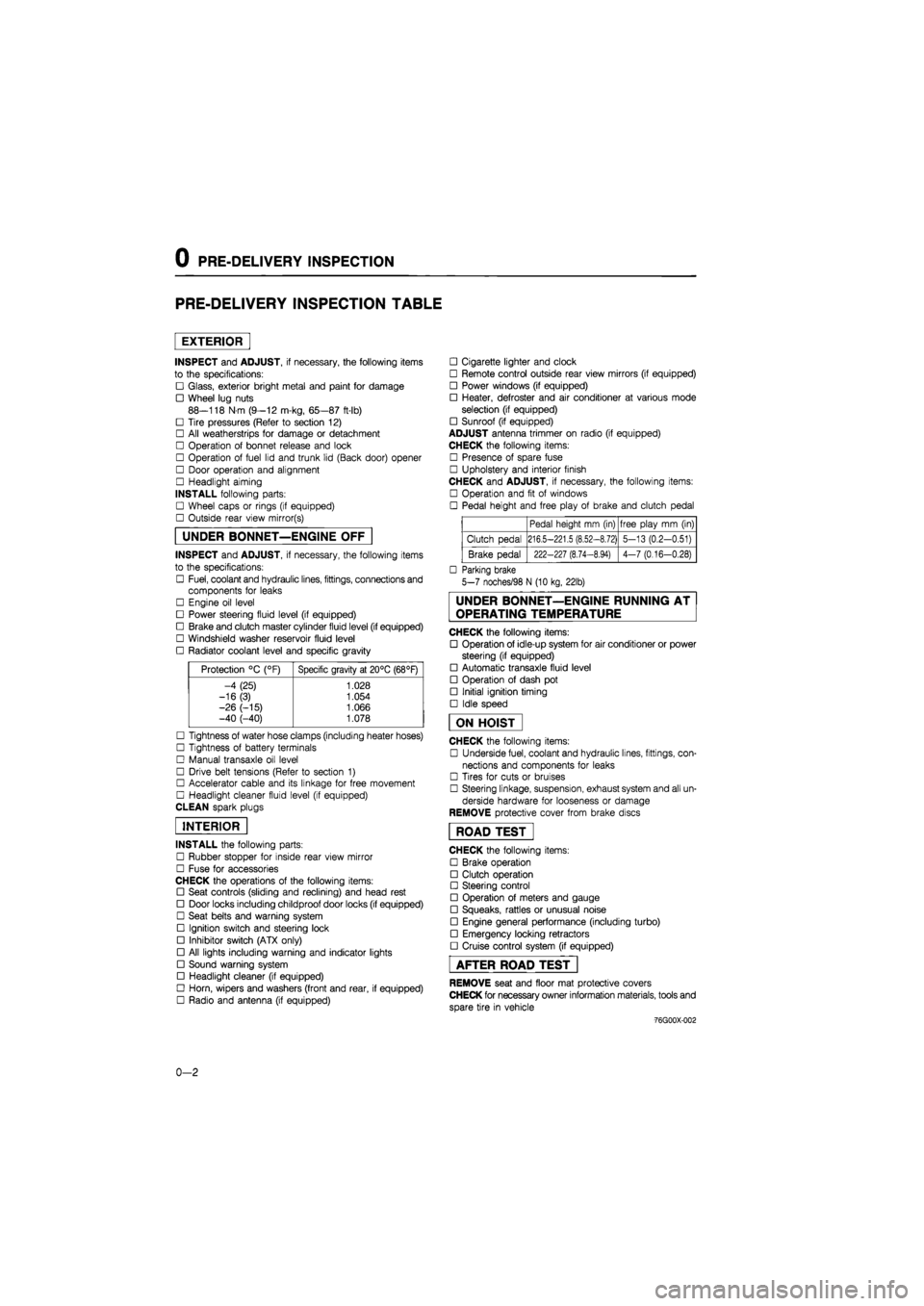
PRE-DELIVERY INSPECTION TABLE
EXTERIOR
INSPECT and ADJUST, if necessary, the following items
to the specifications:
• Glass, exterior bright metal and paint for damage
• Wheel lug nuts
88—118 N m (9—12 m-kg, 65—87 ft-lb)
• Tire pressures (Refer to section 12)
• All weatherstrips for damage or detachment
• Operation of bonnet release and lock
• Operation of fuel lid and trunk lid (Back door) opener
• Door operation and alignment
• Headlight aiming
INSTALL following parts:
• Wheel caps or rings (if equipped)
• Outside rear view mirror(s)
UNDER BONNET—ENGINE OFF
INSPECT and ADJUST, if necessary, the following items
to the specifications:
• Fuel, coolant and hydraulic lines, fittings, connections and
components for leaks
• Engine oil level
• Power steering fluid level (if equipped)
• Brake and clutch master cylinder fluid level (if equipped)
• Windshield washer reservoir fluid level
• Radiator coolant level and specific gravity
Protection °C (°F) Specific gravity at 20°C (68°F)
-4 (25) 1.028
-16(3) 1.054
-26 (-15) 1.066 -40 (-40) 1.078
• Tightness of water hose clamps (including heater hoses)
• Tightness of battery terminals
• Manual transaxle oil level
• Drive belt tensions (Refer to section 1)
• Accelerator cable and its linkage for free movement
• Headlight cleaner fluid level (if equipped)
CLEAN spark plugs
INTERIOR
INSTALL the following parts:
• Rubber stopper for inside rear view mirror
• Fuse for accessories
CHECK the operations of the following items:
• Seat controls (sliding and reclining) and head rest
• Door locks including childproof door locks (if equipped)
• Seat belts and warning system
• Ignition switch and steering lock
• Inhibitor switch (ATX only)
• All lights including warning and indicator lights
• Sound warning system
• Headlight cleaner (if equipped)
• Horn, wipers and washers (front and rear, if equipped)
• Radio and antenna (if equipped)
• Cigarette lighter and clock
• Remote control outside rear view mirrors (if equipped)
• Power windows (if equipped)
• Heater, defroster and air conditioner at various mode
selection (if equipped)
• Sunroof (if equipped)
ADJUST antenna trimmer on radio (if equipped)
CHECK the following items:
• Presence of spare fuse
• Upholstery and interior finish
CHECK and ADJUST, if necessary, the following items:
• Operation and fit of windows
• Pedal height and free play of brake and clutch pedal
Pedal height mm (in) free play mm (in)
Clutch pedal 216.5-221.5 (8.52-8.72) 5-13 (0.2-0.51)
Brake pedal 222-227 (8.74-8.94) 4-7 (0.16-0.28)
• Parking brake
5-7 noches/98 N (10 kg, 22lb)
UNDER BONNET—ENGINE RUNNING AT
OPERATING TEMPERATURE
CHECK the following items:
• Operation of idle-up system for air conditioner or power
steering (if equipped)
• Automatic transaxle fluid level
• Operation of dash pot
• Initial ignition timing
• Idle speed
ON HOIST
CHECK the following items:
• Underside fuel, coolant and hydraulic lines, fittings, con-
nections and components for leaks
• Tires for cuts or bruises
• Steering linkage, suspension, exhaust system and all un-
derside hardware for looseness or damage
REMOVE protective cover from brake discs
ROAD TEST"
CHECK the following items:
• Brake operation
• Clutch operation
• Steering control
• Operation of meters and gauge
• Squeaks, rattles or unusual noise
• Engine general performance (including turbo)
• Emergency locking retractors
• Cruise control system (if equipped)
AFTER ROAD TEST
REMOVE seat and floor mat protective covers
CHECK for necessary owner information materials, tools and
spare tire in vehicle
-76G00X-002
0-2
Page 41 of 1865

TUNE-UP PROCEDURE 1A
High-Tension Lead
Check the following points. Clean or replace if
necessary.
1. Damaged lead
2. Carbon deposits
86U01X-014
76G01A-012
49 0187 280
76G01A-013
Carburetor Float Level (Carburetor)
1. Run the engine at idle.
2. Check that the fuel level is at the center of the float
level indicator window.
If necessary, adjust the fuel float level. (Refer to Sec-
tion 4A.)
Hydraulic Lash Adjuster (12 valve)
Note
Tappet noise may occur if the engine is not
operated for an extended period of time. The
noise should stop after the engine has
reached normal operating temperature.
1. Check for tappet noise. If noise exsits, check the
following points.
(1) Engine oil condition and level
(2) Engine oil pressure (Refer to Section 2A)
2. If the noise does not stop, check for movement of
each HLA by pushing down each rocker arm by
hand while at TDC of compression stroke.
3. If the rocker arm moves down, replace the HLA.
(Refer to page 1A—75.)
76G01A-014
1
A—9
Page 45 of 1865

ON-VEHICLE INSPECTION 1 A
ON-VEHICLE INSPECTION
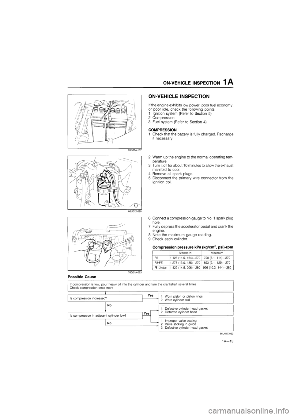
If the engine exhibits low power, poor fuel economy,
or poor idle, check the following points.
1. Ignition system (Refer to Section 5)
2. Compression
3. Fuel system (Refer to Section 4)
COMPRESSION
1. Check that the battery is fully charged. Recharge
if necessary.
76G01A-107
2. Warm up the engine to the normal operating tem-
perature.
3. Turn it off for about 10 minutes to allow the exhaust
manifold to cool.
4. Remove all spark plugs.
5. Disconnect the primary wire connector from the
ignition coil.
86U01X-020
6. Connect a compression gauge to No.
1
spark plug
hole.
7. Fully depress the accelerator pedal and crank the
engine.
8. Note the maximum gauge reading.
9. Check each cylinder.
Compression pressure kPa (kg/cm2, psi)-rpm
Standard Minimum
F6 1,128 (11.5, 164)—270 790 (8.1, 114)—270
F8-FE 1,275 (13.0, 185)—270 893 (9.1, 129)—270
FE 12-valve 1,422 (14.5, 206)—280 996 (10.2, 144)—280
76G01A-023
Possible Cause
86U01X-022
1A—13
Page 79 of 1865

DISASSEMBLY (CYLINDER BLOCK) 1 A
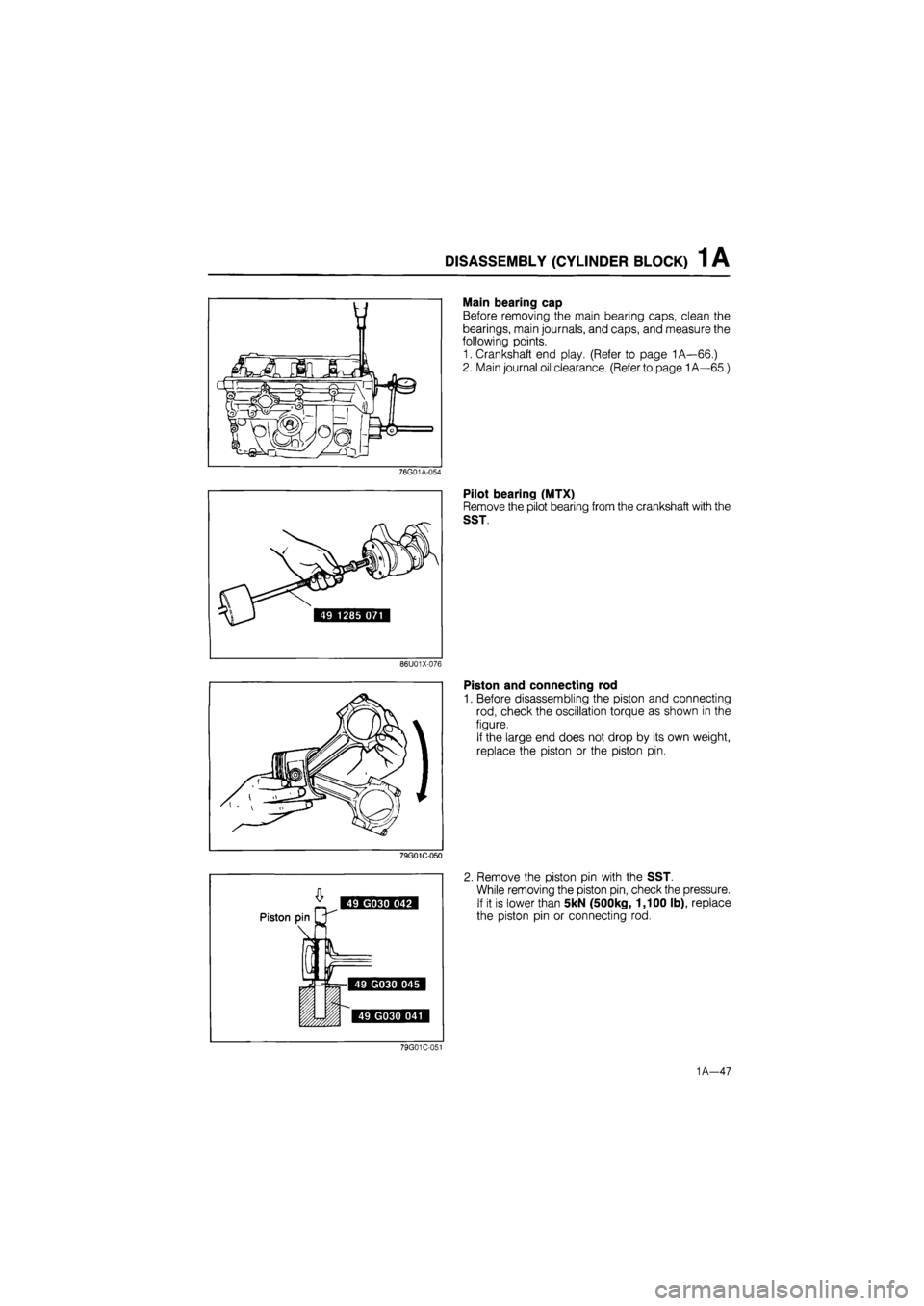
Main bearing cap
Before removing the main bearing caps, clean the
bearings, main journals, and caps, and measure the
following points.
1. Crankshaft end play. (Refer to page 1A—66.)
2. Main journal oil clearance. (Refer to page
1
A—65.)
76G01A-054
Pilot bearing (MTX)
Remove the pilot bearing from the crankshaft with the
SST.
86U01X-076
Piston and connecting rod
1. Before disassembling the piston and connecting
rod, check the oscillation torque as shown in the
figure.
If the large end does not drop by its own weight,
replace the piston or the piston pin.
79G01C-050
2. Remove the piston pin with the SST.
While removing the piston pin, check the pressure.
If it is lower than 5kN (500kg, 1,100 lb), replace
the piston pin or connecting rod.
76G01A-139
1A—47
Page 95 of 1865

ASSEMBLY (CYLINDER BLOCK) 1 A
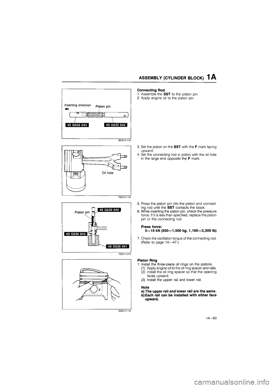
Connecting Rod
1. Assemble the SST to the piston pin.
2. Apply engine oil to the piston pin.
86U01X-118
3. Set the piston on the SST with the F mark facing
upward.
4. Set the connecting rod in piston with the oil hole
in the large end opposite the F mark.
76G01A-135
5. Press the piston pin into the piston and connect-
ing rod until the SST contacts the block.
While inserting the piston pin, check the pressure
force. If it is less than specified, replace the piston
pin or the connecting rod.
Press force:
5—15 kN (500—1,500 kg, 1,100—3,300 lb)
Check the oscillation torque of the connecting rod.
(Refer to page 1A—47.)
76G01A-072
Piston Ring
1. Install the three-piece oil rings on the pistons.
(1) Apply engine oil to the oil ring spacer and rails.
(2) Install the oil ring spacer so that the opening
faces upward.
(3) Install the upper rail and lower rail.
Note
a) The upper rail and lower rail are the same.
b) Each rail can be installed with either face
upward.
69G01A-144
1A—63
Page 129 of 1865

INSTALLATION 1A
Connector Location
Install each harness as shown in the figure.
1. IG coil
2. Engine ground
3. Water temperature sensor
4. P/S switch
5. Oxygen sensor (Fl)
6. Water thermo switch
7. Injection harness (Fl)
8. F/l solenoid (Fl)
76G01A-146
9. Throttle position sensor (Fl)
10. Alternator
11. Oil pressure switch
12. Starter
13. P.T.C. heater (carb.)
14. Solenoid valve (Slow cot) (carb.)
15. Solenoid valve (carb.)
16. Transmission harness
1A—97
Page 139 of 1865

TUNE-UP PROCEDURE 1 B
High-Tension Lead
Check the following points. Clean or replace if
necessary.
1. Damaged lead
2. Carbon deposits
86U01X-014
i^rrr ' /
49 0187 280
76G01B-011
76G01B-012
Hydraulic Lash Adjuster (HLA)
Note
Tappet noise may occur if the engine is not
operated for an extended period of time. The
noise should stop after the engine has
reached normal operating temperature.
1. Check for tappet noise. If noise exists, check the
following points.
(1) Engine oil condition and level
(2) Engine oil pressure (Refer to Section 2A)
2. If the noise does not stop, check for movement of
each HLA by pushing it during disassembly.
3. If the HLA moves, replace the HLA. (Refer to page
1B—60.)
Ignition Timing
1. Warm up the engine and run it at idle.
2. Turn all electric loads OFF.
3. Connect a timing light tester.
4. Disconnect the vacuum hose from the vacuum
control, and plug the hose.
5. Check that the ignition timing mark (yellow) on the
crankshaft pulley and the timing mark on the tim-
ing belt cover are aligned.
Ignition timing: 12° ± 1° BTDC
(at idle speed)
76G01B-008
1B—8
Page 219 of 1865

TUNE-UP PROCEDURE 1C
P/S oil pump Checking point
B
Vacuum/^ i V pumpf o ) y ®
v Rear \ camshaft
J
pulley
A-—mP
P/S oil pump \ L^
76G01C-009
Drive Belt
1. Check the drive belt for wear, cracks, or fraying.
Replace if necessary.
2. Check the drive belt deflection by applying moder-
ate pressure (98 N, 10 kg, 22 lb) midway between
the pulleys.
Alternator
Deflection mm (in)
New 8.0-10.0 (0.31-0.39)
Used 9.0—11.0 (0.35—0.43)
If necessary, loosen the idler lock nut and adjust
the belt deflection by turning the adjust bolt.
Tightening torque:
37—52 N-m (3.8—5.3 m-kg, 27—38 ft-lb)
Vacuum pump and P/S oil pump
Deflection mm (in)
Vacuum
pump
New 7.5-8.5 (0.30-0.33) Vacuum
pump Used 8.5-9.5 (0 33-0.37)
P/S oil pump
New 6.5-7.5 (0.26-0 30) P/S oil pump Used 7.0-8.0 (0.28—0.31)
If necessary, adjust the belt deflection as follows.
(1) Loosen the vacuum pump bolts ©and (§).
(2) Lever the vacuum pump outward and apply
tension to the belt.
(3)Tighten the adjust bolt
Tightening torque:
19—26
N
m (1.9—2.6 m-kg, 14—19 ft-lb)
(4)Tighten the mounting bolt
Tightening torque:
37—52
N
m (3.8—5.3 m-kg, 27—38 ft-lb)
A/C compressor
Deflection mm (in)
New 8.5—9.5 (0.33—0.37)
Used 9.5-10.5 (0.37-0.41)
If necessary, loosen the idler lock nut and adjust
the belt deflection by turning the adjust bolt.
Tightening torque:
37—52 Nm (3.8—5.3 m-kg, 27—38 ft-lb)
1C-7