Page 799 of 1865

CLUTCH RELEASE CYLINDER 6
86U06X-023
86U06X-024
O^CfVYYTi)
I y
Piston cup
76U06X-029
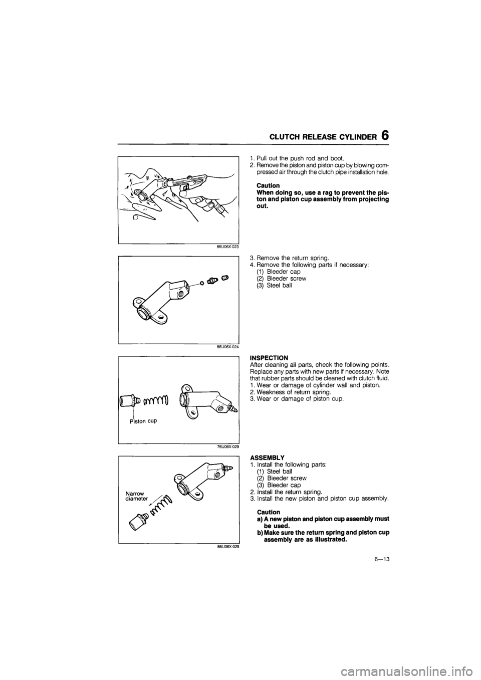
1. Pull out the push rod and boot.
2. Remove the piston and piston cup by blowing com-
pressed air through the clutch pipe installation hole.
Caution
When doing so, use a rag to prevent the pis-
ton and piston cup assembly from projecting
out.
3. Remove the return spring.
4. Remove the following parts if necessary:
(1) Bleeder cap
(2) Bleeder screw
(3) Steel ball
INSPECTION
After cleaning all parts, check the following points.
Replace any parts with new parts if necessary. Note
that rubber parts should be cleaned with clutch fluid.
1. Wear or damage of cylinder wall and piston.
2. Weakness of return spring.
3. Wear or damage of piston cup.
ASSEMBLY
1. Install the following parts:
(1) Steel ball
(2) Bleeder screw
(3) Bleeder cap
2. Install the return spring.
3. Install the new piston and piston cup assembly.
Caution
a) A new piston and piston cup assembly must
be used.
b) Make sure the return spring and piston cup
assembly are as illustrated.
86U06X-025
6—13
Page 800 of 1865

6 AIR BLEEDING
76U06X-031
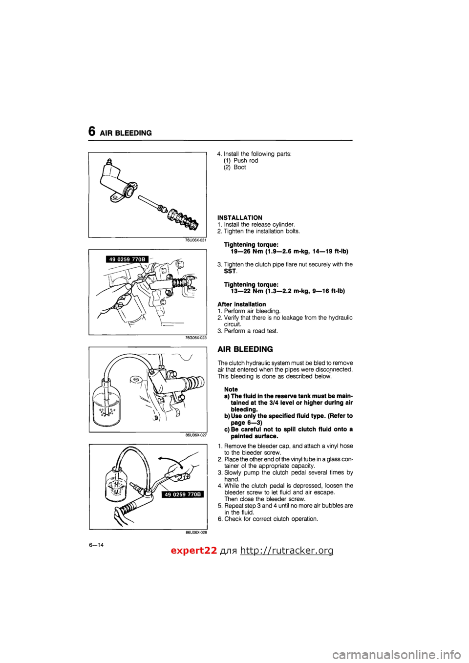
4. Install the following parts:
(1) Push rod
(2) Boot
INSTALLATION
1. Install the release cylinder.
2. Tighten the installation bolts.
Tightening torque:
19—26 N-m (1.9—2.6 m-kg, 14—19 ft-lb)
3. Tighten the clutch pipe flare nut securely with the
SST
Tightening torque:
13—22 N-m (1.3—2.2 m-kg, 9—16 ft-lb)
After installation
1. Perform air bleeding.
2. Verify that there is no leakage from the hydraulic
circuit.
3. Perform a road test.
49 0259 770B
AIR BLEEDING
The clutch hydraulic system must be bled to remove
air that entered when the pipes were disconnected.
This bleeding is done as described below.
Note
a) The fluid in the reserve tank must be main-
tained at the 3/4 level or higher during air
bleeding.
b) Use only the specified fluid type. (Refer to
page 6—3)
c) Be careful not to spill clutch fluid onto a
painted surface.
1. Remove the bleeder cap, and attach a vinyl hose
to the bleeder screw.
2. Place the other end of the vinyl tube in a glass con-
tainer of the appropriate capacity.
3. Slowly pump the clutch pedal several times by
hand.
4. While the clutch pedal is depressed, loosen the
bleeder screw to let fluid and air escape.
Then close the bleeder screw.
5. Repeat step 3 and 4 until no more air bubbles are
in the fluid.
6. Check for correct clutch operation.
86U06X-027
86U06X-028
49 0259 770B
76G06X-023
6—14
expert22 ajia http://rutracker.org
Page 813 of 1865
ON-VEHICLE MAINTENANCE 7A
DRIVESHAFT OIL SEALS
Replacement
Jack up the vehicle, support it on safety stands, and
then drain the transaxle oil. Next, use the following
procedure to replace the driveshaft oil seals:
1. Remove the front wheel(s).
2. Remove the splash shield(s).
3. Separate the front stabilizer from the lower arm.
61G07X-170
4 Remove the bolt and pull the lower arm downward.
Separate the knuckle from the lower arm ball-joint.
Note
Be careful not to damage the ball-joint dust
boot.
Remove the cotter pin then disconnect the tie-rod
end with the SST.
86U07A-009
6. Separate the driveshaft by pulling the front hub out-
ward. Do not use too much force at once, increase
the force gradually.
Note
a) Do not to allow the driveshaft ball-joint to
be bent to its maximum extent.
b) Support the driveshaft using string, wire,
etc.
86U07A-010
7. Remove the oil seal with a flat-tipped screwdriver.
86U07A-011
7A-7
Page 821 of 1865
REMOVAL 7A
86U07A-023
86U07A-024
86U07A-025
11. Disconnect the clutch release cylinder.
12. Disconnect the tie-rod ends using SST.
13. Remove the stabilizer bar control links.
14. Remove the bolts and nuts at the left and right low-
er arm bolt joints.
15. Pull the lower arms downward to separate them
from the knuckles.
Note
Do not damage the ball-joint dust boots.
16. Separate the left driveshaft from the transaxle by
prying with a bar inserted between the shaft and
the case.
Note
Do not damage the oil seal.
17. Remove the joint shaft bracket.
18. Separate the right driveshaft together with the joint
shaft in the same manner.
86U07A-026
7 A—15
Page 826 of 1865
7A DISASSEMBLY
STEP 2
Disassemble in the sequence shown in the figure referring to disassembly note for the specially marked
parts.
76G07A-018
76G07A-019
1. Bearing outer race 15. Selector 28. Roll pin
2. Oil seal 16. Oil seal 29. Reverse lever shaft
3. Bearing outer race 17. Bolt 30. Reverse lever
4. Funnel 18. Bleeder cover 31. Drain plug and washer
5. Bolts 19. Bleeder 32. Neutral switch and gasket
6. Guide plate 20. Bolt 33. Bearing outer race
7. Pipe 21. Speedometer driven gear 34. Diaphragm spring
8. Bolt assembly 35. Adjust shim
9. Change arm 22. O-ring 36. Bearing outer race
10. Roll pin 23. Roll pin 37. Adjust shim
11. Change rod 24. Driven gear 38. Oil seal
12. Boot 25. Gear case 39. Back-up light switch
13. Spring 26. Oil seal 40. Oil passage
14. Reverse gate 27. Bearing outer race
7A-20
Page 848 of 1865
7 A ASSEMBLY
86U07A-106
86U07A-107
86U07A-108
8. Install the new breather.
9. Install the new change rod oil seal.
10. Install the change rod ©, the boot the spring
(3),
the reverse gate @, and selector ©, as shown.
11. Install the new roll pin.
12. Install the change arm.
Tightening torque: 12—14 N-m
(120—140 cm-kg, 104—122 in-lb)
13. Install the guide plate.
Tightening torque:
©8—11 N-m
(80—115 cm-kg, 69—100 in-lb)
(1)22—33 N-m
(2.25—3.35 m-kg, 16—25 ft-lb)
14. Install reverse lever, and reverse lever shaft.
15. Install the new roll pin.
16. Install the speedometer driven gear assembly.
86U07A-109
7A-42
Page 864 of 1865
7A TRANSAXLE CONTROL
TRANSAXLE CONTROL
REMOVAL AND INSTALLATION
1. Jack up the vehicle and support it with safety stands.
2. Remove in the sequence shown in the figure.
3. Install in the reverse order of removal. 61G07X-165
86U07A-230
1. Change lever knob
2. Assist boot
3. Mounting rubber boot
4. Bolts and nuts
5. Change control rod
6. Bracket installation nuts
7. Nut and washer
8. Extension bar bracket as-
sembly and gasket
9. Bushing
10. Pipe
11. Change lever
12. Spring
13. Ball seat (upper)
14. Bushings
15. Boot
16. Holder
17. Ball seat (lower)
18. Extention bar
Note
Apply a coat of grease (lithium base, NLGI No. 2) to the change lever ball, the ball seats,
and each joint.
7A-58
Page 866 of 1865
7A TRANSAXLE CONTROL
Gear Shift Lever Ball
Apply grease to the ball seat surface, and install the
upper and lower ball seat, holder, and boot.
Note
Apply grease to all joints.
61G07X-193
Spring
Make sure that the hooked part of the spring is
properly seated in the bracket groove, as shown in
the figure.
63U07A-156
Bracket Cavity
Put grease in the bracket cavity.
63U07A-157
Change Control Rod
Install the change control rod so that its relationship
with the shift lever is as shown in the figure.
Tightening torque:
16—22
N
m (1.6—2.3 m-kg, 12—17 ft-lb)
61G07X-195
7A-60