Page 1336 of 1865
10 MANUAL STEERING
MANUAL STEERING
DISASSEMBLY
Disassemble in the sequence shown in the figure, referring to the disassembly note for specialy marked
parts.
Note
Before disassembling, drain the gear oil and remove all external grease and dirt.
86U10X088
1. Tie-rod end
2. Nut
3. Clip
4. Boot wire
5. Boot
6. Tie-rod
7. Washer
8. Adjust cover locknut
9. Adjust cover
10. Spring
11. Friction block
12. Dish spring
13. Holder
14. Needle roller
15. Roller assembly
16. Boot support
17. Rear cover locknut
18. Rear cover and oil seal
19. Bearing
20. Pinion
21. Bearing
22. Rack
23. Gear housing
24. Mounting rubber and
bracket
25. Bushing
10—48
Page 1342 of 1865
10 MANUAL STEERING
86U10X-107
86U10X-108
Pinion^ -1
Notch A Y
COSSSSW1
Rack
Central position
86U10X-109
g) Inner surface of housing rack bushing
h) Rack gear and outer circumference of rack shaft
L = 180 mm (7.09 in)
i) Tie-rod ball-joint
j) Inside left and right boots
Caution
Be careful not to fill the ventilation holes in
the rack shaft with grease.
5. Carefully install the rack in the direction of the
arrow.
6. Set the notch of the teeth of the rack at the pinion
position, then insert the pinion.
Caution
This notch is used for adjustment of the pin-
ion bearing preload without the pinion en-
gaged with the rack.
7. Install the upper bearing, and then screw on the
rear cover.
Caution
a) Apply sealant to the threads of the rear
cover.
b)Do not install the oil seal.
c) Screw on the rear cover with the SST.
86U10X-110
10—54
Page 1344 of 1865

10 MANUAL STEERING
86U10X-115
86U10X-116
86U10X-117
Dust Cover
)
2
Oil seal
is Nm
sn n
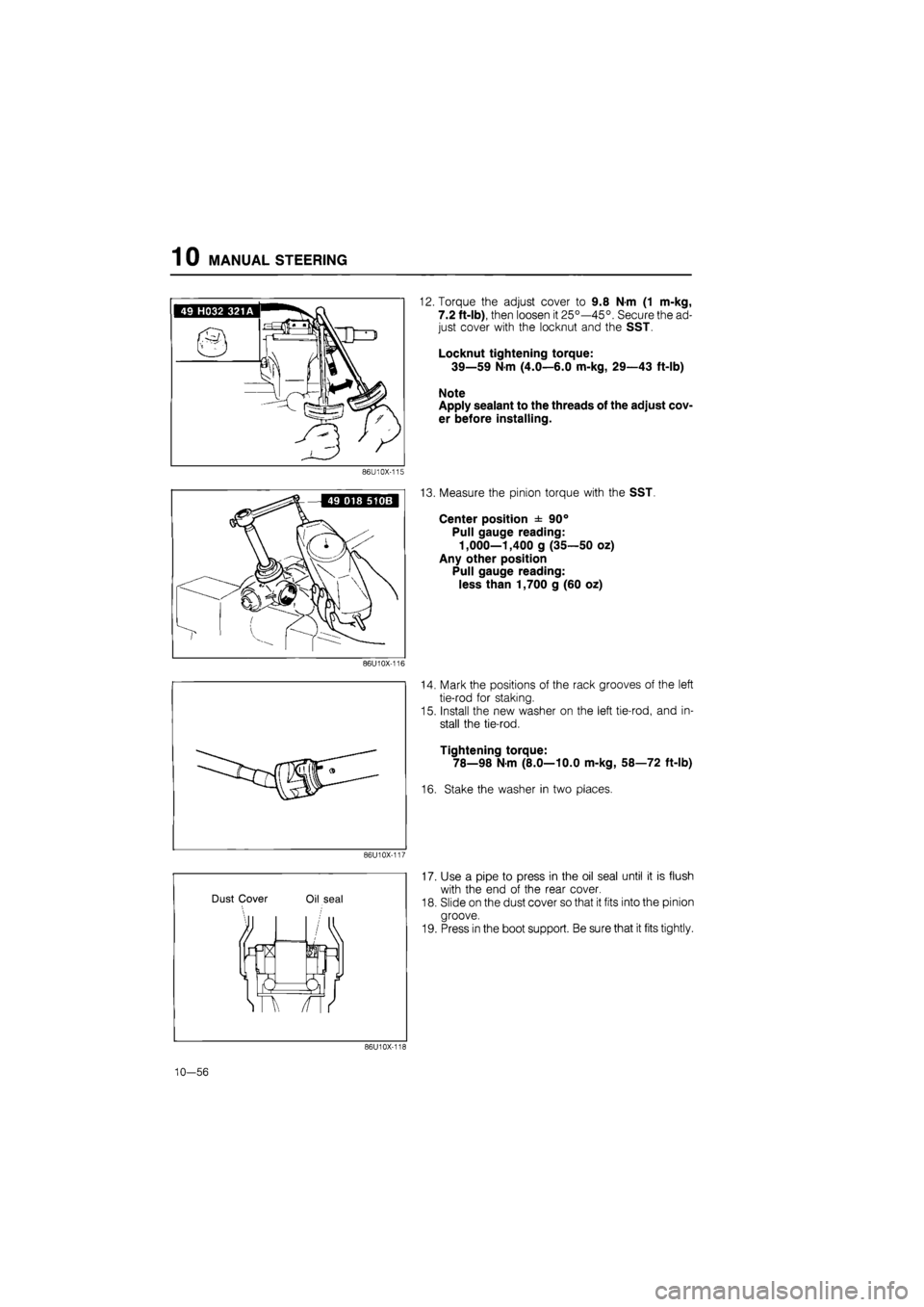
12. Torque the adjust cover to 9.8 N-m (1 m-kg,
7.2 ft-lb), then loosen it 25°—45°. Secure the ad-
just cover with the locknut and the SST.
Locknut tightening torque:
39—59 N-m (4.0—6.0 m-kg, 29—43 ft-lb)
Note
Apply sealant to the threads of the adjust cov-
er before installing.
13. Measure the pinion torque with the SST.
Center position ± 90°
Pull gauge reading:
1,000—1,400 g (35—50 oz)
Any other position
Pull gauge reading:
less than 1,700 g (60 oz)
14. Mark the positions of the rack grooves of the left
tie-rod for staking.
15. Install the new washer on the left tie-rod, and in-
stall the tie-rod.
Tightening torque:
78—98 N-m (8.0—10.0 m-kg, 58—72 ft-lb)
16. Stake the washer in two places.
17. Use a pipe to press in the oil seal until it is flush
with the end of the rear cover.
18. Slide on the dust cover so that it fits into the pinion
groove.
19. Press in the boot support. Be sure that it fits tightly.
86U10X-118
10—56
Page 1345 of 1865
MANUAL STEERING 10
20. Install the boot, then wrap a new wire around it two
times and twist 4 to 4.5 times.
Install the clip.
Caution
Check that the boot is not twisted or dented.
86U10X-119
21. Install the tie-rod ends, aligning them with the marks
made before disassembly.
86U10X-120
10—57
Page 1346 of 1865

1 0 ENGINE SPEED SENSING POWER STEERING
ENGINE SPEED SENSING POWER STEERING
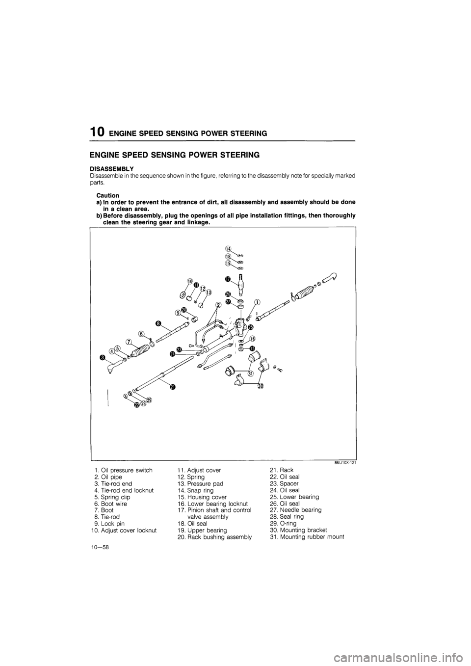
DISASSEMBLY
Disassemble in the sequence shown in the figure, referring to the disassembly note for specially marked
parts.
Caution
a) In order to prevent the entrance of dirt, all disassembly and assembly should be done
in a clean area.
b) Before disassembly, plug the openings of all pipe installation fittings, then thoroughly
clean the steering gear and linkage.
86U10X-121
1. Oil pressure switch
2. Oil pipe
3. Tie-rod end
4. Tie-rod end locknut
5. Spring clip
6. Boot wire
7. Boot
8. Tie-rod
9. Lock pin
10. Adjust cover locknut
11. Adjust cover
12. Spring
13. Pressure pad
14. Snap ring
15. Housing cover
16. Lower bearing locknut
17. Pinion shaft and control
valve assembly
18. Oil seal
19. Upper bearing
20. Rack bushing assembly
21. Rack
22. Oil seal
23. Spacer
24. Oil seal
25. Lower bearing
26. Oil seal
27. Needle bearing
28. Seal ring
29. O-ring
30. Mounting bracket
31. Mounting rubber mount
10—58
Page 1352 of 1865
1 0 ENGINE SPEED SENSING POWER STEERING
Gear housing and boots
1. Gear housing cracking or damage
2. Boot cracking or tearing
86U10X-142
ASSEMBLY
Torque Specifications
as
49—59 N m (5.0—6.0 m-kg, 36—43 ft-lb)
88—98 N m ^ (9.0—10.0 m-kg, 65—72 ft-lb)
31—36 N-m (3.2—3.7 m-kg, 23—27 ft-lb) I j 123-143 N-m / (12.5—14.5 m-kg, / 91-105 ft-lb)
69—98 Nm (7.0—10.0 m-kg, 51—72 ft-lb) 44—54 N-m (4.5—5.5 m-kg, 33—40 ft-lb)
34-44 N-m (3.5—4.5 m-kg, 25—33 ft-lb)
86U10X-251
10-64
Page 1361 of 1865
ENGINE SPEED SENSING POWER STEERING 1 0
3. Tap in a new roll pin.
86U10X-175
i V
vlM^lPl'' \f ) j//
/f
Boot
1. Apply grease to the inner surface of the small end
of the boot.
2. Install the boot. Wrap a new wire around the large
end of the boot two times and then twist it 4 to 4.5
times. Bend the twisted part toward the mounting
bracket.
Note
Be careful not to break the boot wire.
3. Install the spring clip on the small end of the boot.
86U10X-176
Tie-rod end
Align with the mark made before disassembly, and
then tighten the nut.
86U10X-177
Oil pipe
Secure the mounting bracket in a vise so that the oil
pipe connections face upward.
86U10X-178
10-73
Page 1363 of 1865
ELECTRONICALLY-CONTROLLED POWER STEERING 1 0
ELECTRONICALLY-CONTROLLED POWER STEERING
DISASSEMBLY
Disassemble in the sequence shown in the figure, referring to the disassembly note for specially marked
parts.
Caution
a) Because adjustment of the spool valve is not possible, do not disassemble the gear box
for spool valve repairs. If repairs are necessary, replace the gear box assembly.
b) In order to prevent the entrance of dirt, all disassembly and assembly should be done
in a clean area.
c) Before disassembly, plug the openings of all pipe installation fittings; then thoroughly
clean the steering gear and linkage.
86U10X-180
1. Pipe
2. Solenoid valve
3. Tie-rod end
4. Tie-rod end locknut
5. Spring clip
6. Boot wire
7. Boot
8. Tie-rod
9. Adjust cover locknut
10. Adjust cover
11. Spring
12. Pressure pad
13. Outer box assembly
14. Oil seal
15. Mounting bracket
16. Mounting rubber
10—75