Page 10 of 1865

G TOWING
76GOGX-OQ2
i-^C.
y -
- r^jfftj&H
r —I
76UQGX-003
86U0GX-004
G—8
TOWING
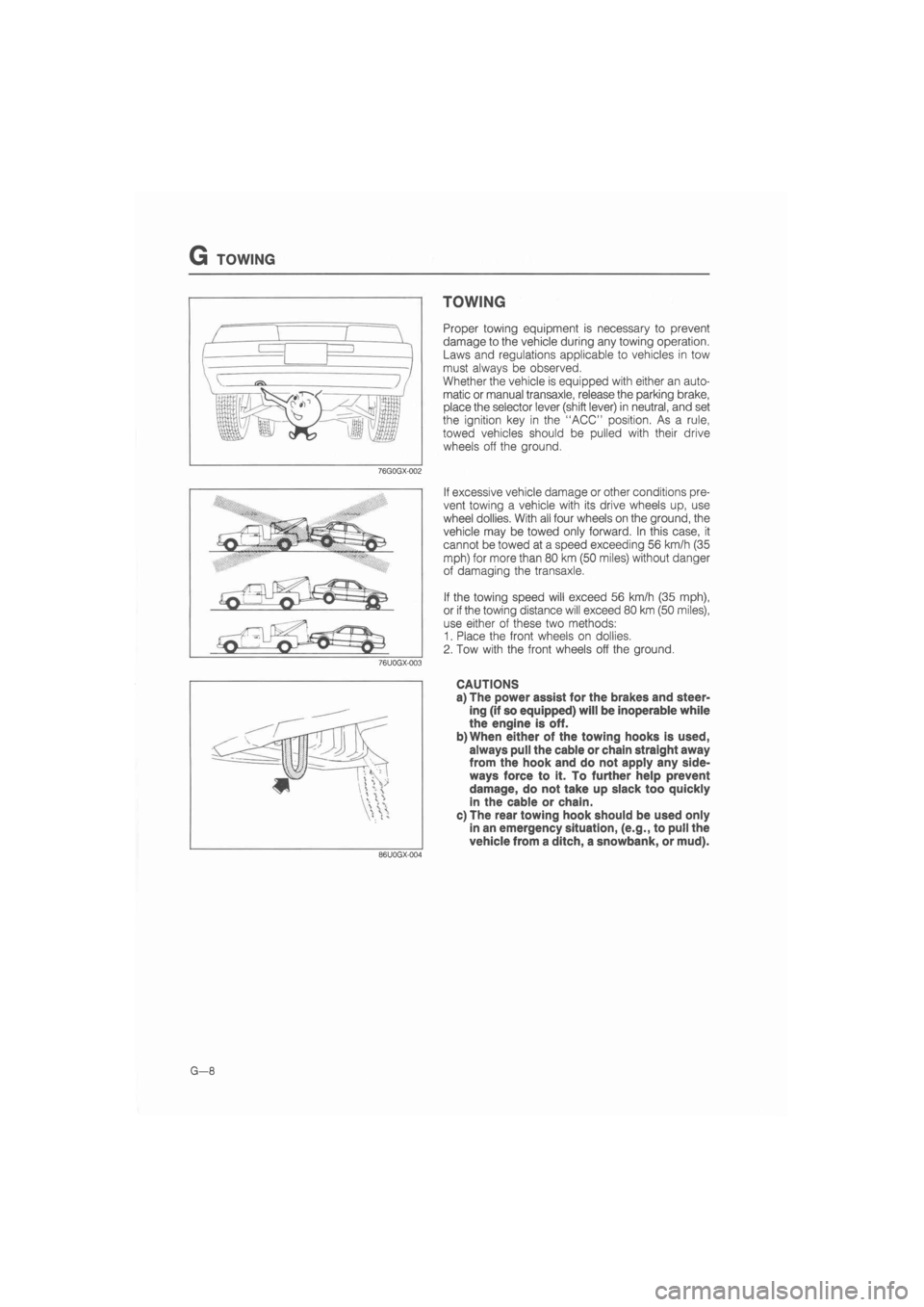
Proper towing equipment is necessary to prevent
damage to the vehicle during any towing operation.
Laws and regulations applicable to vehicles in tow
must always be observed.
Whether the vehicle is equipped with either an auto-
matic or manual transaxle, release the parking brake,
place the selector lever (shift lever) in neutral, and set
the ignition key in the "ACC" position. As a rule,
towed vehicles should be pulled with their drive
wheels off the ground.
If excessive vehicle damage or other conditions pre-
vent towing a vehicle with its drive wheels up, use
wheel dollies. With all four wheels on the ground, the
vehicle may be towed only forward. In this case, it
cannot be towed at a speed exceeding 56 km/h (35
mph) for more than 80 km (50 miles) without danger
of damaging the transaxle.
If the towing speed will exceed 56 km/h (35 mph),
or if the towing distance will exceed 80 km (50 miles),
use either of these two methods:
1. Place the front wheels on dollies.
2. Tow with the front wheels off the ground.
CAUTIONS
a) The power assist for the brakes and steer-
ing (if so equipped) will be inoperable while
the engine is off.
b)When either of the towing hooks is used,
always pull the cable or chain straight away
from the hook and do not apply any side-
ways force to it. To further help prevent
damage, do not take up slack too quickly
in the cable or chain.
c) The rear towing hook should be used only
in an emergency situation, (e.g., to pull the
vehicle from a ditch, a snowbank, or mud).
Page 965 of 1865
DISASSEMBLY 7B
DISASSEMBLY-STEP 3
Component
86U07B-151
1. Transaxle case
2. Output shell
3. Snap ring
4. Spring and retainer assembly
5. Low and reverse brake piston
6. Plug, washer, spring, and detent ball
7. Bracket
8. Manual shaft and manual plate
9. Actuator support
10. Parking assist lever
11. Parking pawl
7B—99
Page 968 of 1865
7B DISASSEMBLY
5. Remove the actuator support.
86U07B-160
86U07B-161
Parking Pawl
6. Remove the snap ring, then remove the parking
assist lever.
7. Remove the parking pawl.
(1) Remove the snap ring.
(2) Pull the parking shaft, then remove the spring
and parking pawl.
86U07B-162
7B—102
Page 1065 of 1865
ASSEMBLY 7B
2. Install the parking assist lever and snap ring.
86U07B-382
86U07B-383
86U07B-384
3. Install the actuator support.
Tightening torque:
11—14 Nm (1.1—1.4 m-kg, 8.0—10 ft-lb)
4. Install the manual shaft and manual plate.
(1) Install the manual plate, spacer, washer, and
nut.
(2) Tighten the nut to specified torque.
Tightening torque:
41—55 Nm (4.2—5.6 m-kg, 30—41 ft-lb)
(3) Install the bracket.
Tightening torque:
8—11 N-m (80—110 cm-kg, 69—95 in-lb)
86U07B-385
7B-199
Page 1487 of 1865

ANTI-LOCK BRAKE SYSTEM (ABS) 1 1
86U11X-190
86U11X-191
76G11X098
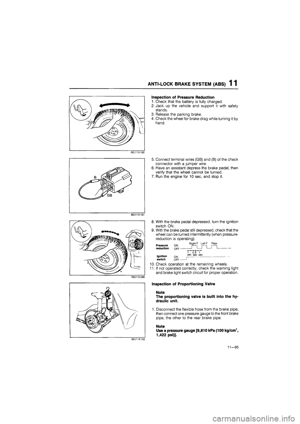
Inspection of Pressure Reduction
1. Check that the battery is fully charged.
2. Jack up the vehicle and support it with safety
stands.
3. Release the parking brake.
4. Check the wheel for brake drag while turning it by
hand.
5. Connect terminal wires (GB) and (B) of the check
connector with a jumper wire.
6. Have an assistant depress the brake pedal; then
verify that the wheel cannot be turned.
7. Run the engine for 10 sec, and stop it.
8. With the brake pedal depressed, turn the ignition
switch ON.
9. With the brake pedal still depressed, check that the
wheel can be turned intermittently (when pressure-
reduction is operating).
Right'F Left F Rear Pressure reduction
Ignition switch ON OFF
1 05 1 sec sec sec
J
10. Check operation at the remaining wheels.
11. If not operated correctly, check the warning light
and brake light switch circuit for proper operation.
Inspection of Proportioning Valve
Note
The proportioning valve is built into the hy-
draulic unit.
1. Disconnect the flexible hose from the brake pipe;
then connect one pressure gauge to the front brake
pipe, the other to the rear brake pipe.
Note
Use a pressure gauge [9,810 kPa (100 kg/cm2,
1,422 psi)].
86U11X-193
11—95