Page 16 of 1865

0 1 Interval
Procedure & item
Number of Months or km, whichever corns first
©1 ©2 ©3 ©4 Service data and inspection point Page
Interval
Procedure & item
Months — 6 12 18 24 30 36 42 48 ©1 ©2 ©3 ©4 Service data and inspection point Page
Interval
Procedure & item
x 1000 Km 1 10 20 30 40 50 60 70 80 ©1 ©2 ©3 ©4 Service data and inspection point Page
Interval
Procedure & item
Miles x
1000 0.6 6 12 18 24 30 36 42 48
©1 ©2 ©3 ©4 Service data and inspection point Page
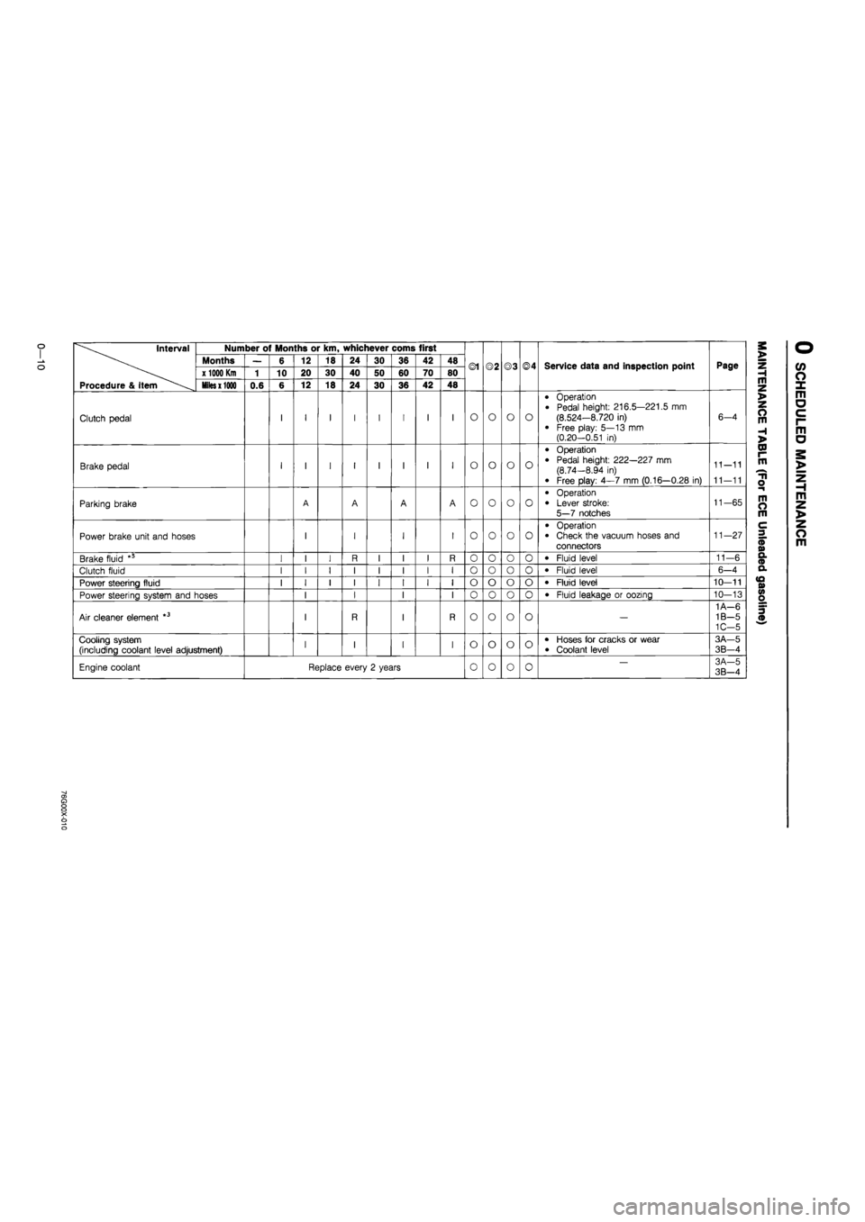
Clutch pedal I 1 I I I I I I O O o o
• Operation
• Pedal height: 216.5—221.5 mm
(8.524—8.720 in) • Free play: 5—13 mm (0.20-0.51 in)
6-4
Brake pedal I 1 I I I I I I O o o o
• Operation
• Pedal height: 222—227 mm (8.74-8.94 in)
• Free play: 4—7 mm (0.16—0.28 in)
11—11
11—11
Parking brake A A A A o o o o
• Operation
• Lever stroke:
5—7 notches
11—65
Power brake unit and hoses 1 I I I o o o o • Operation • Check the vacuum hoses and con-nectors
11—27
Brake fluid " I 1 I R I I I R o o o o • Fluid level 11-6
Clutch fluid I 1 I I I I I I o o o o • Fluid level 6—4
Power steering fluid I 1 I I I I I I
I
o
o"
o
o
o o • Fluid level 10—11
Power steering system and hoses 1 I I
I I
I
o
o"
o
o o o • Fluid leakage or oozing 10—13
Air cleaner element *3 1 R I R —
1A—6 1B—5 1C—5
Choke system 1 I I o o X X
• Carburetor linkage • Choke diaphragm • Choke valve clearance
• Choke Unloader system
4A-26 4A—34 4A—34 4A—33
Cooling system (including coolant level adjustment) 1 I I I o o o o • Hoses for cracks or wear
• Coolant level
3A—5 3B—4
Engine coolant Replace every 2 years o o o o -3A-5 3B-4
Page 22 of 1865

0
1
o
interval
Procedure & Item
Number of Months or km, whichever corns first
©1 ©2 ©3 ©4 Service data and inspection point Page
interval
Procedure & Item
Months — 6 12 18 24 30 36 42 48 ©1 ©2 ©3 ©4 Service data and inspection point Page
interval
Procedure & Item
x
1000 Km
1 10 20 30 40 50 60 70 80 ©1 ©2 ©3 ©4 Service data and inspection point Page
interval
Procedure & Item
Miles x 1000
0.6 6 12 18 24 30 36 42 48
©1 ©2 ©3 ©4 Service data and inspection point Page
Clutch pedal I I I I I I I I O o o o
• Operation
• Pedal height: 216.5—221.5 mm (8.524—8.720 in)
• Free play: 5—13 mm (0.20—0.51 in)
6-4
Brake pedal I I I I I I I I O o o o
• Operation • Pedal height: 222—227 mm (8.74—8.94 in)
• Free play: 4—7 mm (0.16—0.28 in)
11-11
11—11
Parking brake A A A A o o o o
• Operation • Lever stroke: 5—7 notches
11-65
Power brake unit and hoses I I I I o o o o
• Operation • Check the vacuum hoses and connectors
11—27
Brake fluid *5 I I I R I I I R 0 o o o • Fluid level 11—6
Clutch fluid I I I I I I I I o o o 0 • Fluid level 6-4
Power steering fluid I I I I I I I I o o o o • Fluid level 10—11
Power steering system and hoses I I I I 0 o o 0 • Fluid leakage or oozing 10—13
Air cleaner element *3 I R I R o o o o —
1 A—6 1B—5 1C-5
Cooling system (including coolant level adjustment) I I I I o o o o • Hoses for cracks or wear • Coolant level
3A—5
3B-4
Engine coolant Replace every 2 years 0 o 0 0 — 3A-5 3B—4
a> a o o X o o
Page 696 of 1865
FUEL SYSTEM 4D
RF-CX
o
M
o
10-
RF-N
M
m
M
o TO"
5-
76G04D-059
76G04D-060
76G04D-061
3. Turn the crankshaft, and align the flywheel indica-
tor pin at ATDC 10 (RF-CX), or TDC 0° (RF-N).
4. Turn the injection pump until the dial indicator in-
dicates 1 mm (0.04 in).
Note
Refer to page 4D—4 for initial setting of the
dial indicator.
Cam Height Inspection
1. Set the SST into the injection pump as for injec-
tion timing adjustment. (Refer to page 4D—4.)
2. Turn the crankshaft clockwise and read the maxi-
mum difference of the indicator value, which gives
the cam height.
Cam height: 2.2 mm (0.08 in)
76G04D-062
4D—25
Page 787 of 1865
CLUTCH
OUTLINE 6— 2
STRUCTURAL VIEW 6— 2
SPECIFICATIONS 6— 3
TROUBLESHOOTING GUIDE 6— 3
ON-VEHICLE MAINTENANCE 6— 4
FLUID LEVEL 6— 4
PEDAL HEIGHT 6— 4
PEDAL FREEPLAY 6— 4
CLUTCH PEDAL 6— 5
REMOVAL 6— 5
INSPECTION 6— 6
INSTALLATION 6— 6
ADJUSTMENT 6— 6
CLUTCH MASTER CYLINDER 6— 7
REMOVAL 6— 7
DISASSEMBLY 6—8
INSPECTION 6— 9
ASSEMBLY 6— 9
INSTALLATION 6—11
CLUTCH RELEASE CYLINDER 6—11
REMOVAL 6—12
DISASSEMBLY 6-12
INSPECTION 6—13
ASSEMBLY 6—13
INSTALLATION 6—14
AIR BLEEDING 6—14
CLUTCH AND FLYWHEEL 6—15
REMOVAL 6—15
INSPECTION 6—16
INSTALLATION 6—19
76G06X-001
Page 790 of 1865

6 ON-VEHICLE MAINTENANCE
6-4
ON-VEHICLE MAINTENANCE
FLUID LEVEL
1. Clean the area around the reservoir and the reser-
voir cap.
2. Check the fluid level. If the level is near or below
the "MIN" mark, add clutch fluid to the "MAX"
mark.
Fluid specification:
DOT-3 or DOT-4
(FMVSS 116, or SAE J1703)
PEDAL HEIGHT
Inspection
Measure the distance from the upper center of the
pedal pad to the firewall and ensure that the distance
is within specification.
Pedal height A:
216.5—221.5 mm (8.524—8.720 in)
Adjustment
To adjust the pedal height, loosen locknut and turn
stopper bolt or clutch switch.
PEDAL FREEPLAY
Inspection
Depress the pedal lightly by hand and measure the
freeplay to ensure that it is within specification.
Pedal freeplay: 5—13 mm (0.20—0.51 in)
Adjustment
1. Adjust the free play by loosening locknut C and
turning push rod D.
2. Check that the distance from the floor to the cen-
ter of the upper surface of the pedal pad is as
specified or more when the clutch is fully dis-
engaged.
Disengagement height B:
LHD 68 mm (2.7 in)
RHD 85 mm (3.3 in)
3. Tighten locknut C after adjustment.
Page 792 of 1865
6 CLUTCH PEDAL
INSPECTION
Check the following, and repair or replace any faulty
parts.
1. Worn or damaged pedal bushing
2. Twisted or bent pedal
3. Worn or damaged pedal pad
76G06X-008
INSTALLATION
Install in the reverse order of removal referring to the
installation note.
Installation Note
Apply grease (lithium base, NLGI No.2) to the
bushings.
76G06X-009
ADJUSTMENT
1. Adjust the pedal height. (Refer to page 6—4.)
2. Check the pedal free play, and adjust if necessary.
(Refer to page 6—4.)
3. Adjust the installation length of the assist spring.
The installation length is adjusted by turning nut
A show in the figure and adjusting dimension B.
Standard dimension:
38.6—39.6 (1.520—1.559 in)
76G06X-010
6-6
Page 1403 of 1865

BRAKE PEDAL 1 1
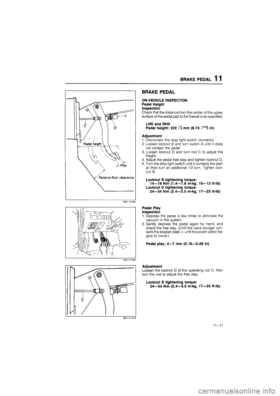
Pedal height
"tt^
Pedal-to-floor clearance
76G11X-008
BRAKE PEDAL
ON-VEHICLE INSPECTION
Pedal Height
Inspection
Check that the distance from the center of the upper
surface of the pedal pad to the firewall is as specified.
LHD and RHD
Pedal height: 222 mm (8.74 +0-200 in)
Adjustment
1. Disconnect the stop light switch connector.
2. Loosen locknut B and turn switch A until it does
not contact the pedal.
3. Loosen locknut D and turn rod C to adjust the
height.
4. Adjust the pedal free play and tighten locknut D.
5. Turn the stop light switch until it contacts the ped-
al; then turn an additional 1/2 turn. Tighten lock-
nut B.
Locknut B tightening torque:
14—18 N m (1.4—1.8 m-kg, 10—13 ft-lb)
Locknut D tightening torque:
24—34 Nm (2.4—3.5 m-kg, 17—25 ft-lb)
Pedal Play
Inspection
1. Depress the pedal a few times to eliminate the
vacuum in the system.
2. Gently depress the pedal again by hand, and
check the free play. (Until the valve plunger con-
tacts the stopper plate = until the power piston be-
gins to move.)
Pedal play: 4—7 mm (0.16—0.28 in)
76G11X-099
Adjustment
Loosen the locknut D of the operating rod C; then
turn the rod to adjust the free play.
Locknut D tightening torque:
24—34 Nm (2.4—3.5 m-kg, 17—25 ft-lb)
86U11X-018
11—11
Page 1417 of 1865
MASTER CYLINDER 1 1
Adjustment
Adjust the piston to push rod clearance in the follow-
ing order.
1. For (a) of judgement table
(1) Measure the height of (D) and record after
removing the SST from the master cylinder.
76G11X-028
Adjust nut
(2) Install the SST again to the master cylinder,
and turn the adjust nut so that clearance (C)
between the SST and the master cylinder is
0 mm (Oin).
(3) Measure the height of (E) when clearance (C)
is 0 mm (Oin).
(E) — (D) = Projecting amount of the power
brake unit push rod
76G11X-029
(4) Remove the push rod from the power brake
unit.
63G11X-349
(5) Make the piston to push rod clearance 0 mm
(Oin) by turning the push rod and shortening
the push rod length by the amount of (E) — (D).
Note
The threads of the push rod are specially
designed so that the push rod bolt becomes
harder to turn past a certain point to prevent
loosening of the bolt. Turn the push rod bolt
only within this range when adjusting.
76G11X030
11—25