1987 MAZDA 626 warning
[x] Cancel search: warningPage 4 of 1865
G IMPORTANT INFORMATION/FUNDAMENTAL PROCEDURES
IMPORTANT INFORMATION
BASIC ASSUMPTIONS
This workshop manual assumes that you have arid know how to properly use certain special tools
which are necessary for the safe and efficient performance of service operations on Mazda vehicles.
The manual also assumes that you are familiar generally with automobile systems and basic service
and repair procedures. You should not attempt to use this manual unless these assumptions are cor-
rect and you understand the consequences described below.
SAFETY RISK
This manual contains certain notes, warnings, etc., which you should carefully read and follow in or-
der to eliminate the risk of personal injury to yourself or others and the risk of improper service which
may damage the vehicle or render it unsafe. The fact that there are no such notes, etc., with respect
to any specific service method does not mean that there is no possibility that personal safety or vehicle
safety will be jeopardized by the use of incorrect methods or tools.
POSSIBLE LOSS OF WARRANTY
The manufacturer's warranty on Mazda vehicles and engines can be voided if improper service or
repairs are performed by persons other than an authorized Mazda dealer.
FUNDAMENTAL PROCEDURES
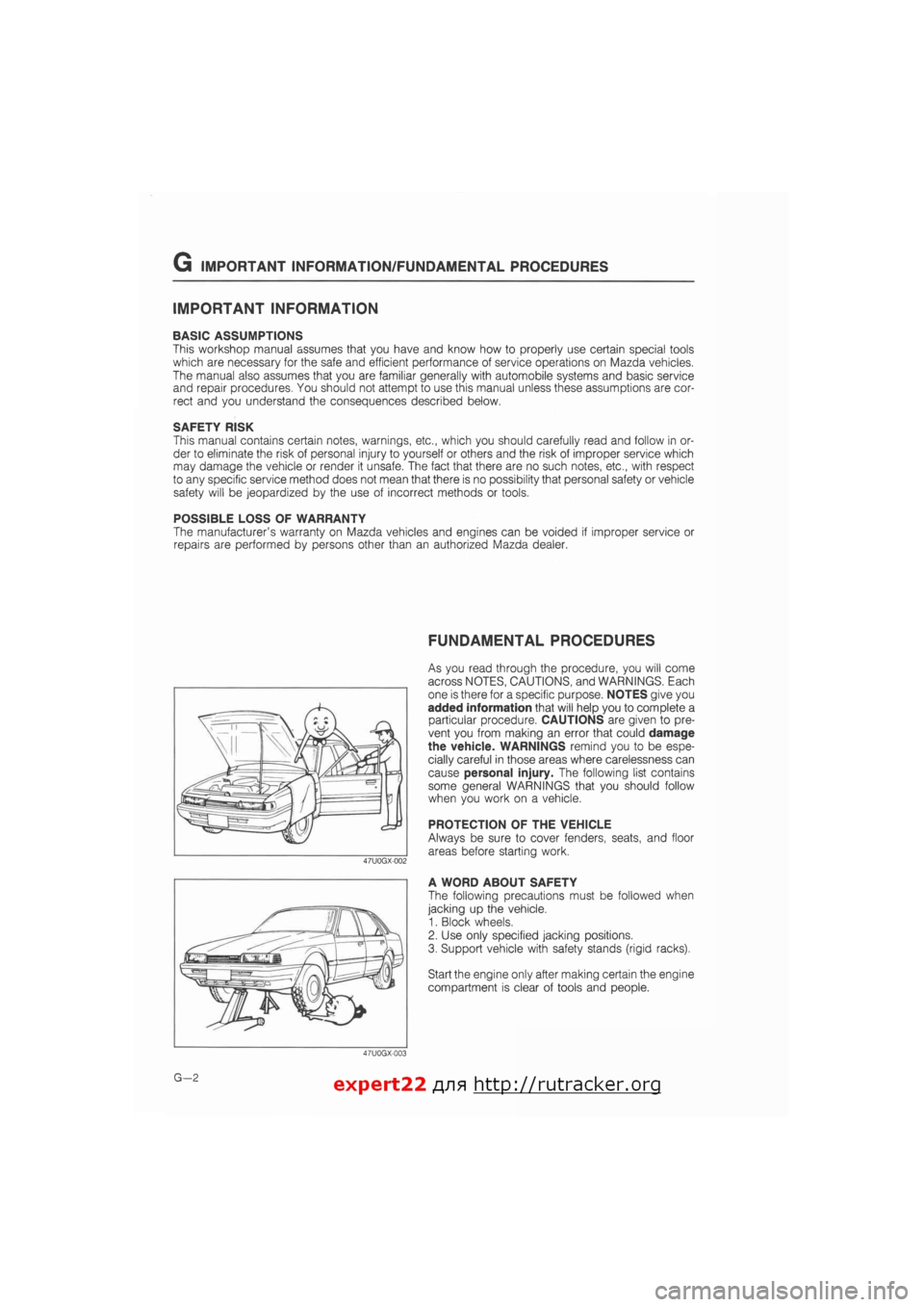
As you read through the procedure, you will come
across NOTES, CAUTIONS, and WARNINGS. Each
one is there for a specific purpose. NOTES give you
added information that will help you to complete a
particular procedure. CAUTIONS are given to pre-
vent you from making an error that could damage
the vehicle. WARNINGS remind you to be espe-
cially careful in those areas where carelessness can
cause personal injury. The following list contains
some general WARNINGS that you should follow
when you work on a vehicle.
PROTECTION OF THE VEHICLE
Always be sure to cover fenders, seats, and floor
areas before starting work.
A WORD ABOUT SAFETY
The following precautions must be followed when
jacking up the vehicle.
1. Block wheels.
2. Use only specified jacking positions.
3. Support vehicle with safety stands (rigid racks).
Start the engine only after making certain the engine
compartment is clear of tools and people.
G—2 expert22 fl/i* http://rutracker.org
Page 14 of 1865
0 PRE-DELIVERY INSPECTION
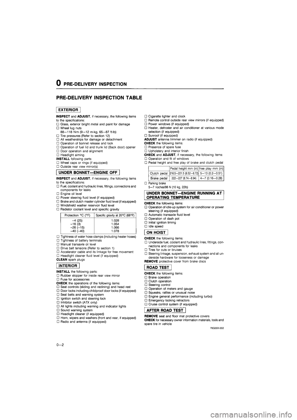
PRE-DELIVERY INSPECTION TABLE
EXTERIOR
INSPECT and ADJUST, if necessary, the following items
to the specifications:
• Glass, exterior bright metal and paint for damage
• Wheel lug nuts
88—118 N m (9—12 m-kg, 65—87 ft-lb)
• Tire pressures (Refer to section 12)
• All weatherstrips for damage or detachment
• Operation of bonnet release and lock
• Operation of fuel lid and trunk lid (Back door) opener
• Door operation and alignment
• Headlight aiming
INSTALL following parts:
• Wheel caps or rings (if equipped)
• Outside rear view mirror(s)
UNDER BONNET—ENGINE OFF
INSPECT and ADJUST, if necessary, the following items
to the specifications:
• Fuel, coolant and hydraulic lines, fittings, connections and
components for leaks
• Engine oil level
• Power steering fluid level (if equipped)
• Brake and clutch master cylinder fluid level (if equipped)
• Windshield washer reservoir fluid level
• Radiator coolant level and specific gravity
Protection °C (°F) Specific gravity at 20°C (68°F)
-4 (25) 1.028
-16(3) 1.054
-26 (-15) 1.066 -40 (-40) 1.078
• Tightness of water hose clamps (including heater hoses)
• Tightness of battery terminals
• Manual transaxle oil level
• Drive belt tensions (Refer to section 1)
• Accelerator cable and its linkage for free movement
• Headlight cleaner fluid level (if equipped)
CLEAN spark plugs
INTERIOR
INSTALL the following parts:
• Rubber stopper for inside rear view mirror
• Fuse for accessories
CHECK the operations of the following items:
• Seat controls (sliding and reclining) and head rest
• Door locks including childproof door locks (if equipped)
• Seat belts and warning system
• Ignition switch and steering lock
• Inhibitor switch (ATX only)
• All lights including warning and indicator lights
• Sound warning system
• Headlight cleaner (if equipped)
• Horn, wipers and washers (front and rear, if equipped)
• Radio and antenna (if equipped)
• Cigarette lighter and clock
• Remote control outside rear view mirrors (if equipped)
• Power windows (if equipped)
• Heater, defroster and air conditioner at various mode
selection (if equipped)
• Sunroof (if equipped)
ADJUST antenna trimmer on radio (if equipped)
CHECK the following items:
• Presence of spare fuse
• Upholstery and interior finish
CHECK and ADJUST, if necessary, the following items:
• Operation and fit of windows
• Pedal height and free play of brake and clutch pedal
Pedal height mm (in) free play mm (in)
Clutch pedal 216.5-221.5 (8.52-8.72) 5-13 (0.2-0.51)
Brake pedal 222-227 (8.74-8.94) 4-7 (0.16-0.28)
• Parking brake
5-7 noches/98 N (10 kg, 22lb)
UNDER BONNET—ENGINE RUNNING AT
OPERATING TEMPERATURE
CHECK the following items:
• Operation of idle-up system for air conditioner or power
steering (if equipped)
• Automatic transaxle fluid level
• Operation of dash pot
• Initial ignition timing
• Idle speed
ON HOIST
CHECK the following items:
• Underside fuel, coolant and hydraulic lines, fittings, con-
nections and components for leaks
• Tires for cuts or bruises
• Steering linkage, suspension, exhaust system and all un-
derside hardware for looseness or damage
REMOVE protective cover from brake discs
ROAD TEST"
CHECK the following items:
• Brake operation
• Clutch operation
• Steering control
• Operation of meters and gauge
• Squeaks, rattles or unusual noise
• Engine general performance (including turbo)
• Emergency locking retractors
• Cruise control system (if equipped)
AFTER ROAD TEST
REMOVE seat and floor mat protective covers
CHECK for necessary owner information materials, tools and
spare tire in vehicle
-76G00X-002
0-2
Page 39 of 1865
1A TUNE-UP PROCEDURE
Coolant Level (Cold engine)
1. Check that the coolant level is near the radiator inlet
port.
2. Check that the level in the coolant reservoir is be-
tween the FULL and LOW marks.
Add coolant if necessary.
Warning
a) Never remove the radiator cap while the en-
gine is hot.
b) Wrap a thick cloth around the cap and care-
fully remove it.
86U01X-008
When set
When measured
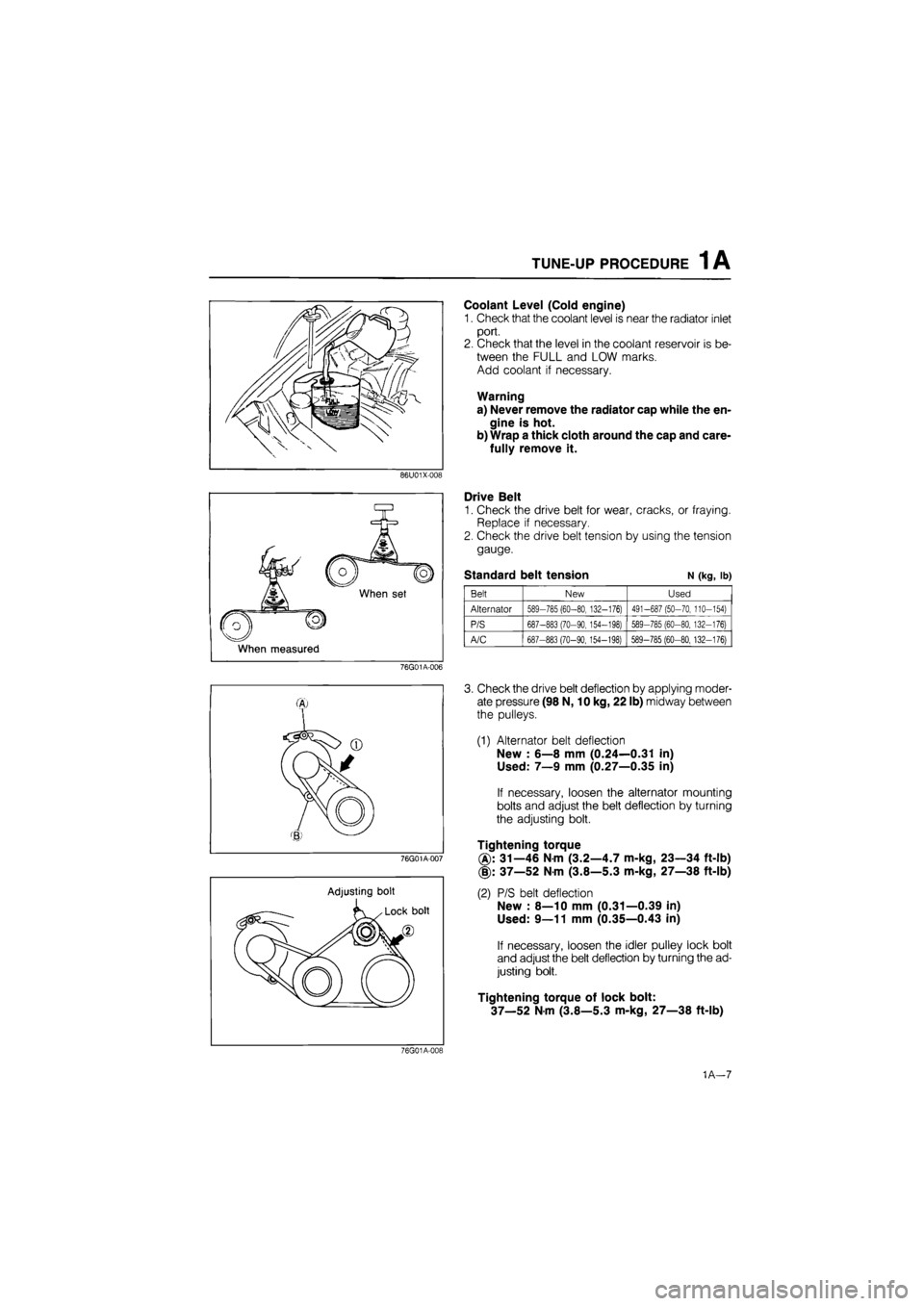
Drive Belt
1. Check the drive belt for wear, cracks, or fraying.
Replace if necessary.
2. Check the drive belt tension by using the tension
gauge.
Standard belt tension N (kg, lb)
Belt New Used
Alternator 589-785 (60-80, 132-176) 491-687 (50-70, 110-154)
P/S 687-883 (70-90, 154-198) 589-785 (60-80, 132-176)
A/C 687-883 (70-90,154-198) 589-785 (60-80, 132-176)
76G01A-006
76G01A-007
Adjusting bolt
3. Check the drive belt deflection by applying moder-
ate pressure (98 N, 10 kg, 22 lb) midway between
the pulleys.
(1) Alternator belt deflection
New : 6—8 mm (0.24—0.31 in)
Used: 7—9 mm (0.27—0.35 in)
If necessary, loosen the alternator mounting
bolts and adjust the belt deflection by turning
the adjusting bolt.
Tightening torque
31—46 Nm (3.2—4.7 m-kg, 23—34 ft-lb)
(§): 37—52 Nm (3.8—5.3 m-kg, 27—38 ft-lb)
(2) P/S belt deflection
New : 8—10 mm (0.31—0.39 in)
Used: 9—11 mm (0.35—0.43 in)
If necessary, loosen the idler pulley lock bolt
and adjust the belt deflection by turning the ad-
justing bolt.
Tightening torque of lock bolt:
37—52 Nm (3.8—5.3 m-kg, 27—38 ft-lb)
76G01A-019
1A—7
Page 52 of 1865
1 A ON-VEHICLE MAINTENANCE (CYLINDER HEAD)
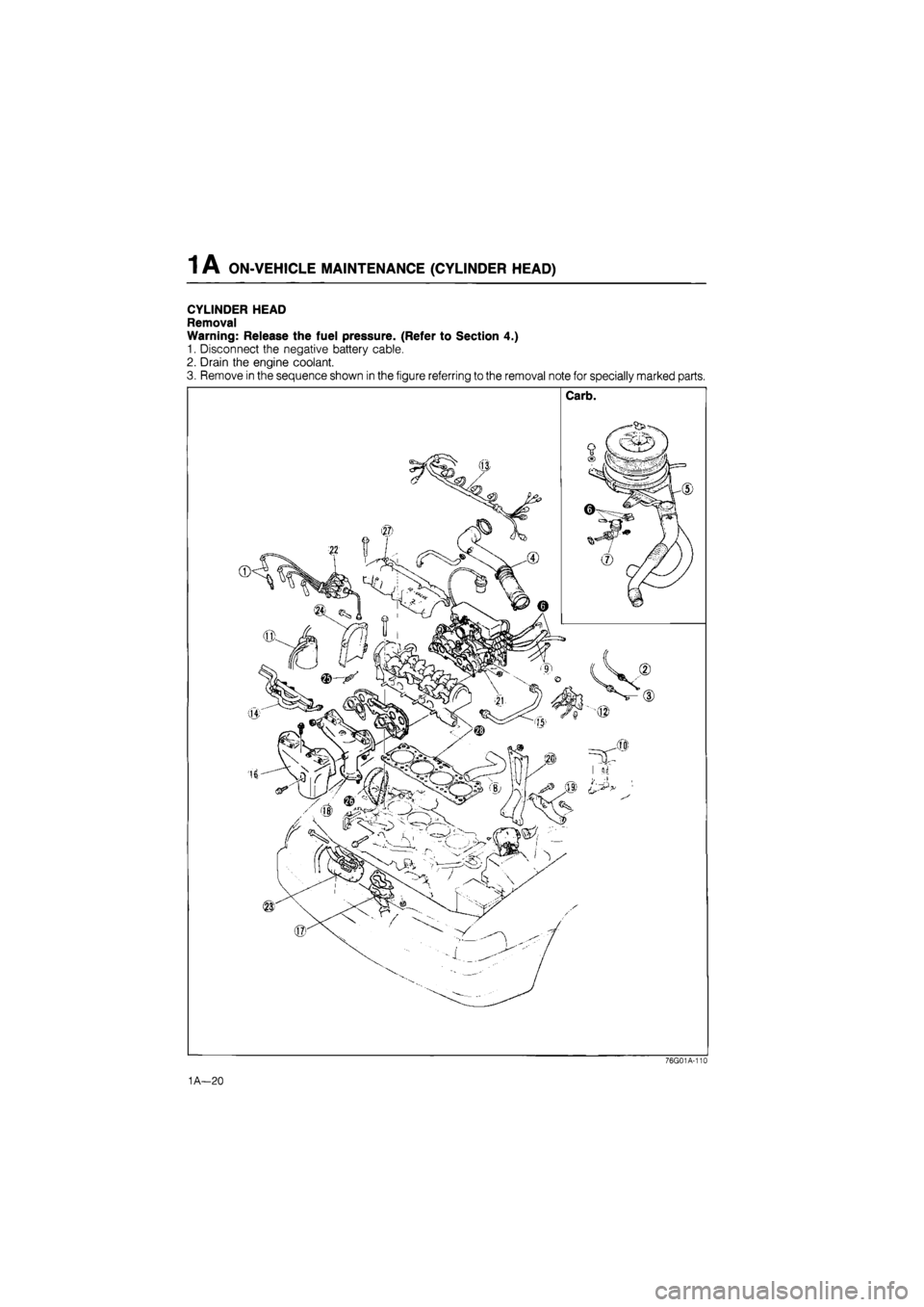
CYLINDER HEAD
Removal
Warning: Release the fuel pressure. (Refer to Section 4.)
1. Disconnect the negative battery cable.
2. Drain the engine coolant.
3. Remove in the sequence shown in the figure referring to the removal note for specially marked parts.
76G01A-110
1A—20
Page 53 of 1865
1 A ON-VEHICLE MAINTENANCE (CYLINDER HEAD)
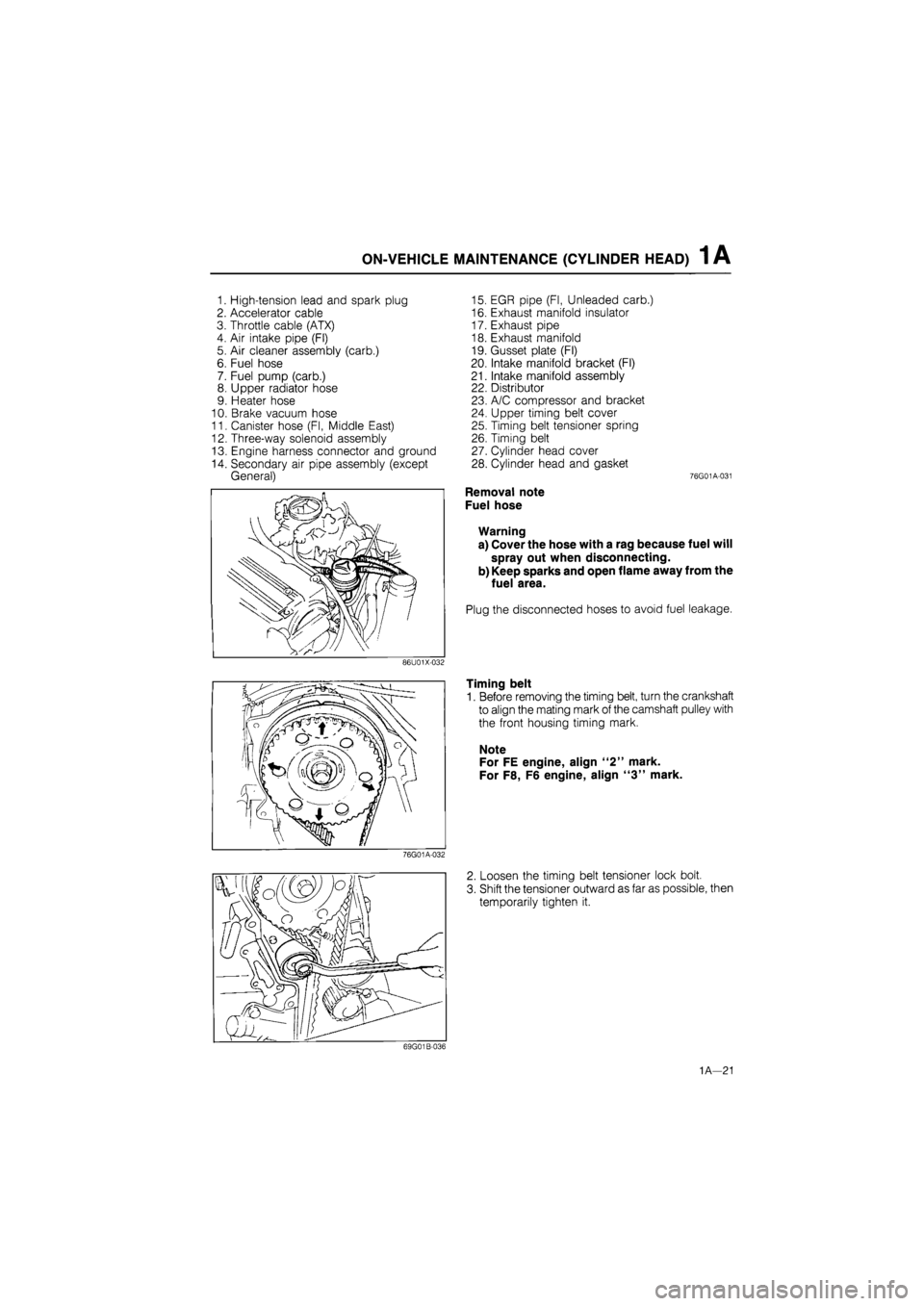
1. High-tension lead and spark plug
2. Accelerator cable
3. Throttle cable (ATX)
4. Air intake pipe (Fl)
5. Air cleaner assembly (carb.)
6. Fuel hose
7. Fuel pump (carb.)
8. Upper radiator hose
9. Heater hose
10. Brake vacuum hose
11. Canister hose (Fl, Middle East)
12. Three-way solenoid assembly
13. Engine harness connector and ground
14. Secondary air pipe assembly (except
General)
15. EGR pipe (Fl, Unleaded carb.)
16. Exhaust manifold insulator
17. Exhaust pipe
18. Exhaust manifold
19. Gusset plate (Fl)
20. Intake manifold bracket (Fl)
21. Intake manifold assembly
22. Distributor
23. A/C compressor and bracket
24. Upper timing belt cover
25. Timing belt tensioner spring
26. Timing belt
27. Cylinder head cover
28. Cylinder head and gasket 76G01A-031
Removal note
Fuel hose
Warning
a) Cover the hose with a rag because fuel will
spray out when disconnecting.
b) Keep sparks and open flame away from the
fuel area.
Plug the disconnected hoses to avoid fuel leakage.
Timing belt
1. Before removing the timing belt, turn the crankshaft
to align the mating mark of the camshaft pulley with
the front housing timing mark.
Note
For FE engine, align "2" mark.
For F8, F6 engine, align "3" mark.
2. Loosen the timing belt tensioner lock bolt.
3. Shift the tensioner outward as far as possible, then
temporarily tighten it.
1A—21
Page 66 of 1865
1A REMOVAL
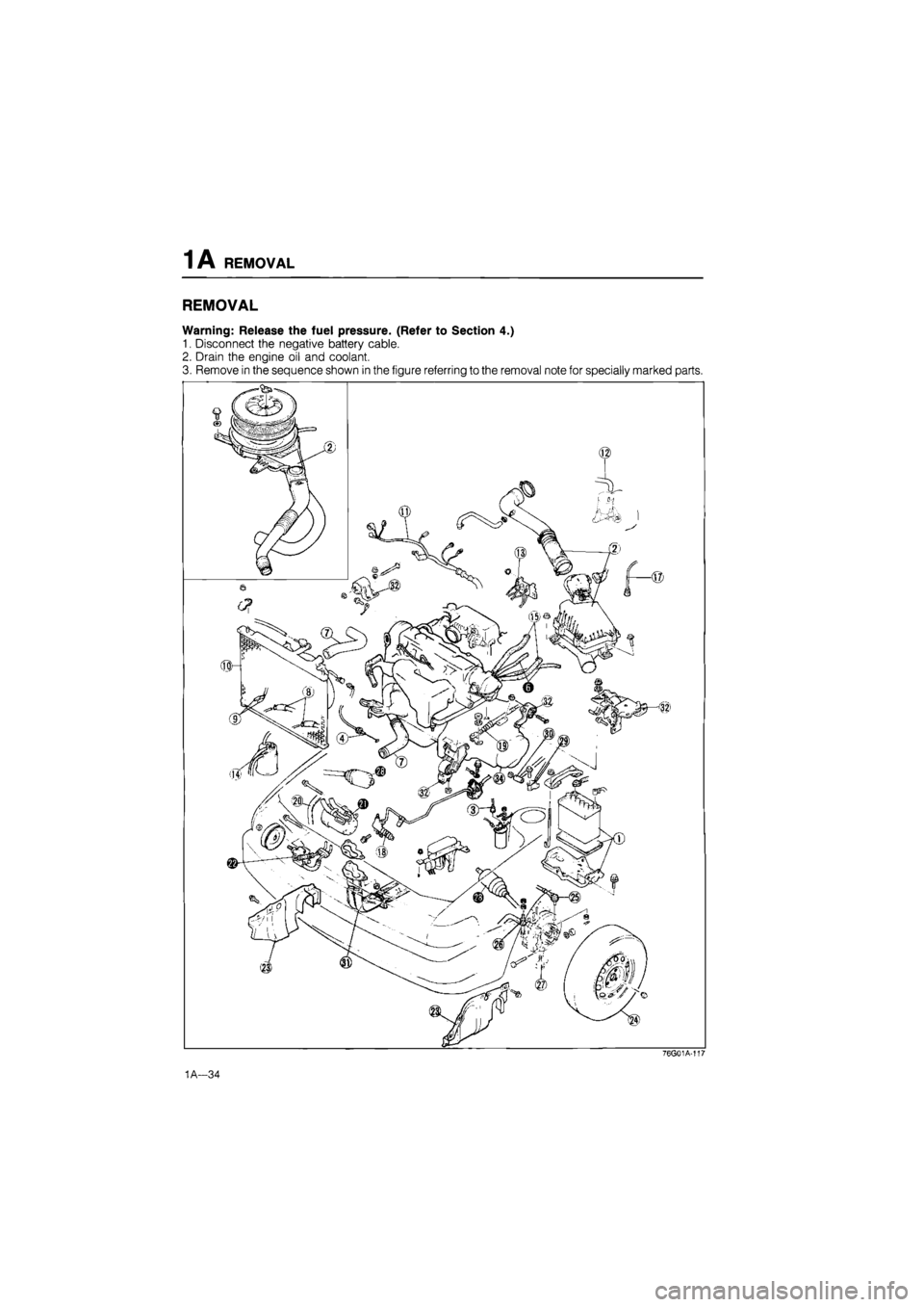
REMOVAL
Warning: Release the fuel pressure. (Refer to Section 4.)
1. Disconnect the negative battery cable.
2. Drain the engine oil and coolant.
3. Remove in the sequence shown in the figure referring to the removal note for specially marked parts.
76GG1A-117
1A—34
Page 67 of 1865
REMOVAL 1A
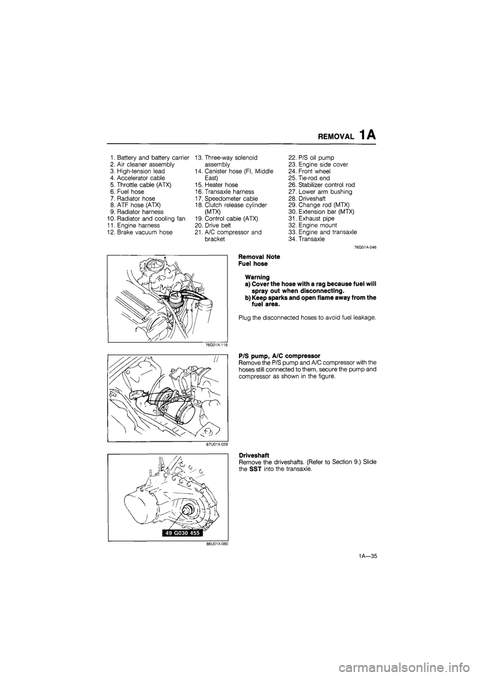
1. Battery and battery carrier 13. Three-way solenoid 22. P/S oil pump
2. Air cleaner assembly assembly 23. Engine side cover
3. High-tension lead 14. Canister hose (Fl, Middle 24. Front wheel
4. Accelerator cable East) 25. Tie-rod end
5. Throttle cable (ATX) 15. Heater hose 26. Stabilizer control rod
6. Fuel hose 16. Transaxle harness 27. Lower arm bushing
7. Radiator hose 17. Speedometer cable 28. Driveshaft
8. ATF hose (ATX) 18. Clutch release cylinder 29. Change rod (MTX)
9. Radiator harness (MTX) 30. Extension bar (MTX)
10. Radiator and cooling fan 19. Control cable (ATX) 31. Exhaust pipe
11. Engine harness 20. Drive belt 32. Engine mount
12. Brake vacuum hose 21. A/C compressor and 33. Engine and transaxle
bracket 34. Transaxle
76G01A-046
Removal Note
Fuel hose
Warning
a) Cover the hose with a rag because fuel will
spray out when disconnecting.
b) Keep sparks and open flame away from the
fuel area.
Plug the disconnected hoses to avoid fuel leakage.
76G01A-11E
P/S pump, A/C compressor
Remove the P/S pump and A/C compressor with the
hoses still connected to them, secure the pump and
compressor as shown in the figure.
67U01X-029
Driveshaft
Remove the driveshafts. (Refer to Section 9.) Slide
the SST into the transaxle.
86U01X-060
1A—35
Page 124 of 1865
1A INSTALLATION
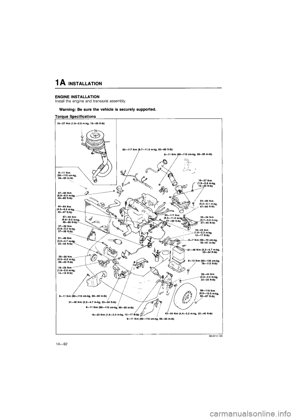
ENGINE INSTALLATION
Install the engine and transaxle assembly.
Warning: Be sure the vehicle is securely supported.
Torque Specifications
16—27 N-m (1.6—2.8 m-kg, 12—20 ft-lb)
.OT-
9
85—117 N-m (6.7-11.9 m-kg, 63—86 ft-lb)
8—11 N-m (80—110 cm-kg, 69—95 In-lb)
44—64 N-m I (4.5—6.5 m-kg,
_
33-47 ft-lb)
16—27 N-m (1.6—2.8 m-kg, 12—20 ft-lb)
/ 64—89 N-m (6.5—9.1 m-kg, 47—66 ft-lb)
37—52 N-m (3.8—5.3 m-kg, 27—38 ft-lb)
31—46 N-m (3.2-4.7 m-i 23—34 ft-lb)
39—59 N-m _ (4.0—6.0 m-kg, 29—43 ft-lb)
19—25 N-m (1.9—2.6 m-kg, 14—1S ft-lb)
36-54 N-m (3.7—5.5 m-kg, 27—40 ft-lb)
16—23 N-m (1.6—2.3 m-kg, 12—17 ft-lb)
5—7 N-m (50—70 cm-kg, 43—61 In-lb)
-31—46 N-m (3.2—4.7 m-kg, 23—34 ft-lb)
9—13 N m (90—130 cm-kg, 78—113 ft-lb)
29—44 N-m (3.0—4.5 m-kg, 22—33 ft-lb)
8-11 N-m (80—110 cm-kg, 69—95
31—46 N-m (3.2—4.7 m-kg.
8—11 N-m (80
16—23
88—118 N-m (9.0—12.0 m-kg, 65—87 ft-lb)
43—54 N-m (4.4—5.5 m-kg, 32—40 ft-lb)
8—11 N-m (80—110 cm-kg, 69—95 In-lb)
86U01X-180
1A—92