1987 MAZDA 626 tire pressure
[x] Cancel search: tire pressurePage 14 of 1865

0 PRE-DELIVERY INSPECTION
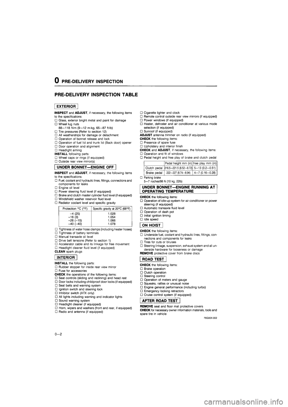
PRE-DELIVERY INSPECTION TABLE
EXTERIOR
INSPECT and ADJUST, if necessary, the following items
to the specifications:
• Glass, exterior bright metal and paint for damage
• Wheel lug nuts
88—118 N m (9—12 m-kg, 65—87 ft-lb)
• Tire pressures (Refer to section 12)
• All weatherstrips for damage or detachment
• Operation of bonnet release and lock
• Operation of fuel lid and trunk lid (Back door) opener
• Door operation and alignment
• Headlight aiming
INSTALL following parts:
• Wheel caps or rings (if equipped)
• Outside rear view mirror(s)
UNDER BONNET—ENGINE OFF
INSPECT and ADJUST, if necessary, the following items
to the specifications:
• Fuel, coolant and hydraulic lines, fittings, connections and
components for leaks
• Engine oil level
• Power steering fluid level (if equipped)
• Brake and clutch master cylinder fluid level (if equipped)
• Windshield washer reservoir fluid level
• Radiator coolant level and specific gravity
Protection °C (°F) Specific gravity at 20°C (68°F)
-4 (25) 1.028
-16(3) 1.054
-26 (-15) 1.066 -40 (-40) 1.078
• Tightness of water hose clamps (including heater hoses)
• Tightness of battery terminals
• Manual transaxle oil level
• Drive belt tensions (Refer to section 1)
• Accelerator cable and its linkage for free movement
• Headlight cleaner fluid level (if equipped)
CLEAN spark plugs
INTERIOR
INSTALL the following parts:
• Rubber stopper for inside rear view mirror
• Fuse for accessories
CHECK the operations of the following items:
• Seat controls (sliding and reclining) and head rest
• Door locks including childproof door locks (if equipped)
• Seat belts and warning system
• Ignition switch and steering lock
• Inhibitor switch (ATX only)
• All lights including warning and indicator lights
• Sound warning system
• Headlight cleaner (if equipped)
• Horn, wipers and washers (front and rear, if equipped)
• Radio and antenna (if equipped)
• Cigarette lighter and clock
• Remote control outside rear view mirrors (if equipped)
• Power windows (if equipped)
• Heater, defroster and air conditioner at various mode
selection (if equipped)
• Sunroof (if equipped)
ADJUST antenna trimmer on radio (if equipped)
CHECK the following items:
• Presence of spare fuse
• Upholstery and interior finish
CHECK and ADJUST, if necessary, the following items:
• Operation and fit of windows
• Pedal height and free play of brake and clutch pedal
Pedal height mm (in) free play mm (in)
Clutch pedal 216.5-221.5 (8.52-8.72) 5-13 (0.2-0.51)
Brake pedal 222-227 (8.74-8.94) 4-7 (0.16-0.28)
• Parking brake
5-7 noches/98 N (10 kg, 22lb)
UNDER BONNET—ENGINE RUNNING AT
OPERATING TEMPERATURE
CHECK the following items:
• Operation of idle-up system for air conditioner or power
steering (if equipped)
• Automatic transaxle fluid level
• Operation of dash pot
• Initial ignition timing
• Idle speed
ON HOIST
CHECK the following items:
• Underside fuel, coolant and hydraulic lines, fittings, con-
nections and components for leaks
• Tires for cuts or bruises
• Steering linkage, suspension, exhaust system and all un-
derside hardware for looseness or damage
REMOVE protective cover from brake discs
ROAD TEST"
CHECK the following items:
• Brake operation
• Clutch operation
• Steering control
• Operation of meters and gauge
• Squeaks, rattles or unusual noise
• Engine general performance (including turbo)
• Emergency locking retractors
• Cruise control system (if equipped)
AFTER ROAD TEST
REMOVE seat and floor mat protective covers
CHECK for necessary owner information materials, tools and
spare tire in vehicle
-76G00X-002
0-2
Page 888 of 1865

7B TROUBLESHOOTING (G4A-EL)
STEP 2 (PRELIMINARY INSPECTION)
In this step, the fundamental points related to the automatic transaxle are checked. These points must
be kept in the correct condition at all times in order to assure proper operation of the automatic transaxle.
1. Automatic Transmission Fluid (ATF)
Check ATF level and condition. (Refer to page 7B—71)
2. Selector Lever
Check selector lever position and adjust if necessary. (Refer to page 7B—72)
76G07B-022
3. Throttle cable
(1) Check the inner and outer cable for damage.
(2) Make sure that the accelerator operates
smoothly.
76G07B-023
4. Idle Speed
Check idle speed. (Refer to Section 4B)
5. Tire Inflation Pressure
Check tire inflation pressure. (Refer to Section 12)
76G07B-024
6. Inhibitor Switch
Check the inhibitor switch for operation. (Refer to
page 7B—65)
76G07B-025
7B-22
Page 912 of 1865

7B TROUBLESHOOTING (G4A-HL)
5. Throttle Cable
(1) Check the inner and outer cable for damage.
(2) Make sure that the accelerator operates
smoothly.
76g07b-046
6. Idle Speed
Check idle speed. (Refer to Section 4A)
7. Tire Inflation Pressure
Check tire inflation pressure. (Refer to Section 12)
8. Ignition Timing
Check ignition timing. (Refer to Section 5)
7B-46
Page 941 of 1865

ON-VEHICLE MAINTENANCE 7B
'mfm^i! kfOl iff t—
76G07B-093
76G07B-094
Main fuse block (G4A-EL)
Install the main fuse block.
Tightening torque:
8—11 Nm (80—110 cm-kg, 69—95 in-lb)
Battery carrier
Install the battery carrier.
Tightening torque:
31—40 Nm (3.2—4.1 m-kg, 23—30 ft-lb)
ATF level
After installation, add ATF, and with the engine idling,
check the fluid level and for leaks. (Refer to page
7 B—71)
Adjustment (G4A-EL)
1. Remove the splash shield next to the left front tire.
2. Remove the square head plug L and install the
SST
3. Shift into P range and start the engine. Warm up
the engine to normal operating temperature, and
adjust the idle speed.
Idle speed: 950 ±5o rpm
76G07B-095
3 CO CO 03
(1)
L
Line pressure
beeing to increase
I
Adjusting point
•
clockwise Counter
clockwise Position of locknuts
86U07B-482
4. Adjust locknuts as follows:
When the locknuts are moved, line pressure is in-
creased or decreased as shown. Adjust the lock-
nuts to the correct position using the following
procedure.
(1) Initially install the locknuts fully away from the
throttle cam. (Loosen the cable all the way)
(2) Adjust the locknuts in a clockwise direction as
viewed from the front of the vehicle until the
line pressure begins to increase above the
specification shown below.
7B—75
Page 942 of 1865

7B ON-VEHICLE MAINTENANCE
Line pressure decreases
Line pressure increases
86U07B-483
Protector
-7 / Throttle cable
86U07B-080
(3) Adjust the locknuts in a counterclockwise direc-
tion until the line pressure decreases to the
specification. Tighten the locknuts.
Specified pressure: 432—450 kPa
(4.4—4.6 kg/cm2, 63—66 psi)
Note
Transmission in P range
5. Turn off the engine.
6. Reinstall the square head plug.
Tightening torque:
5—10 N m (50—100 cm-kg, 43—87 in-lb)
7. Fully open the throttle valve; then crimp the pin with
the protector installed as shown.
8. Remove the protector.
Adjustment (G4A-HL)
1. Remove the splash shield next to the left front tire.
2. Remove the square head plug T and install the
SST
3. Shift into P range and start the engine. Warm up
the engine to normal operating temperature, and
adjust the idle speed.
Idle speed: 900 -5o rpm
76G07B-096
3 tn tn
L
Counter- ^ clockwise
Throttle pressure
beeing to increase
I Adjusting point
Position of locknuts
Clockwise
4. Adjust locknuts as follows:
When the locknuts are moved, throttle pressure is
increased or decreased as shown. Adjust the lock-
nuts to the correct position using the following
procedure.
(1) Initially install the locknuts fully away from the
throttle cam. (Loosen the cable all the way)
(2) Adjust the locknuts in a clockwise direction as
viewed from the front of the vehicle until the
throttle pressure begins to increase above the
specification shown below.
76G07B-097
7B—76
Page 1122 of 1865

7C TROUBLESHOOTING
TROUBLESHOOTING
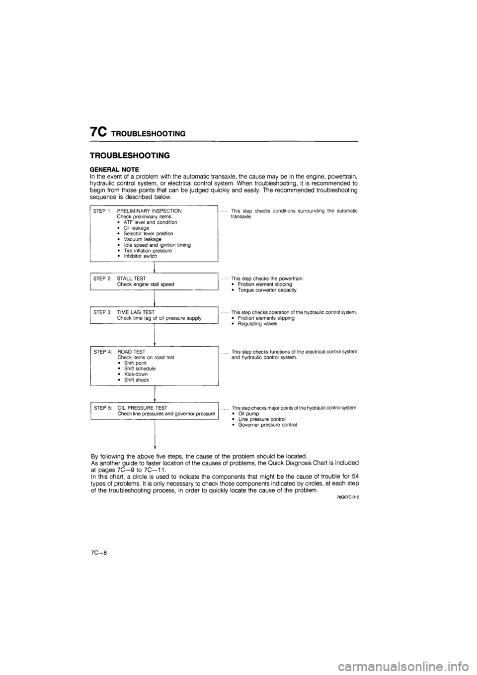
GENERAL NOTE
In the event of a problem with the automatic transaxle, the cause may be in the engine, powertrain,
hydraulic control system, or electrical control system. When troubleshooting, it is recommended to
begin from those points that can be judged quickly and easily. The recommended troubleshooting
sequence is described below.
STEP 1: PRELIMINARY INSPECTION Check preliminary items • ATF level and condition
• Oil leakage • Selector lever position
• Vacuum leakage
• Idle speed and ignition timing
• Tire inflation pressure • Inhibitor switch
This step checks conditions surrounding the automatic
transaxle.
STEP 2: STALL TEST Check engine stall speed This step checks the powertrain.
• Friction element slipping
• Torque converter capacity
STEP 3: TIME LAG TEST Check time lag of oil pressure supply This step checks operation of the hydraulic control system. • Friction elements slipping
• Regulating valves
STEP 4: ROAD TEST Check items on road test
• Shift point • Shift schedule
• Kick-down • Shift shock
This step checks functions of the electrical control system
and hydraulic control system.
STEP 5: OIL PRESSURE TEST Check line pressures and governor pressure This step checks major points of the hydraulic control system.
• Oil pump • Line pressure control • Governer pressure control
By following the above five steps, the cause of the problem should be located.
As another guide to faster location of the causes of problems, the Quick Diagnosis Chart is included
at pages 7C—9 to 7C—11.
In this chart, a circle is used to indicate the components that might be the cause of trouble for 54
types of problems. It is only necessary to check those components indicated by circles, at each step
of the troubleshooting process, in order to quickly locate the cause of the problem.
76G07C-012
7C—8
Page 1127 of 1865

TROUBLESHOOTING 7C
76G07C-020
76G07C-021
76G07C-022
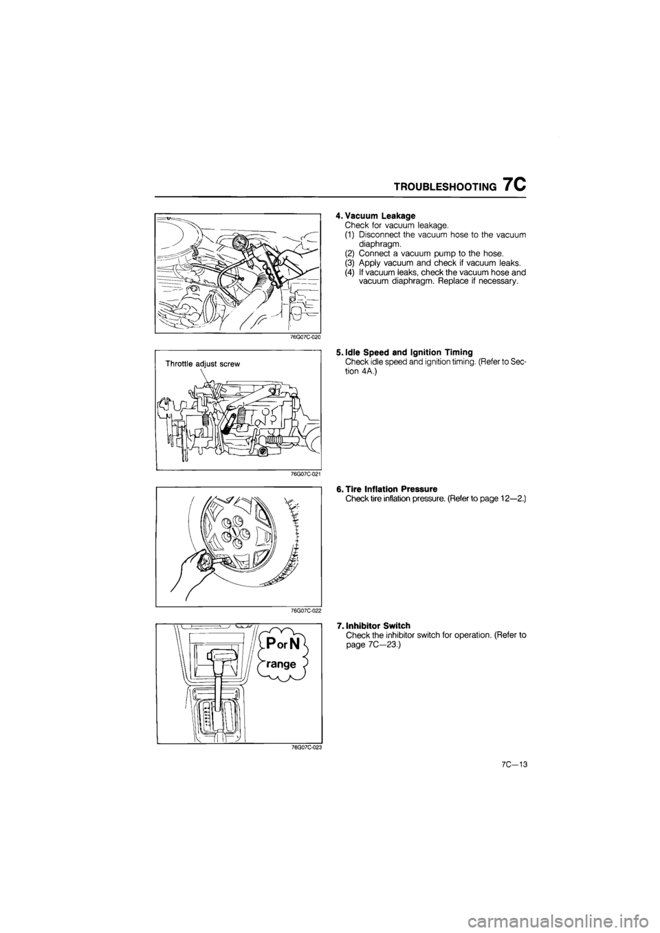
4. Vacuum Leakage
Check for vacuum leakage.
(1) Disconnect the vacuum hose to the vacuum
diaphragm.
(2) Connect a vacuum pump to the hose.
(3) Apply vacuum and check if vacuum leaks.
(4) If vacuum leaks, check the vacuum hose and
vacuum diaphragm. Replace if necessary.
5. Idle Speed and Ignition Timing
Check idle speed and ignition timing. (Refer to Sec-
tion 4A.)
6. Tire Inflation Pressure
Check tire inflation pressure. (Refer to page 12—2.)
7. Inhibitor Switch
Check the inhibitor switch for operation. (Refer to
page 7C—23.)
76G07C-023
7C-13
Page 1256 of 1865

TROUBLESHOOTING GUIDE 9
TROUBLESHOOTING GUIDE
Problem Possible Cause Remedy Page
Faulty operation of
driveshaft
Broken ball joint
Broken tri-pod joint
Worn or seized joint
Replace
Replace
Replace
9—31
9—35
9—31, 35
Abnormal noise from driveshaft Insufficient grease in joint or spline Excessive backlash on spline Worn joint
Add or replace
Replace
Replace
9—33, 36 9—31, 35 9-31, 35
Steering wheel pulls. (Steering wheel pulls toward either right or left side)
Bent steering linkage
Fatigued coil spring
Lower arm bushing worn or damaged Bent knuckle Bent lower arm or loose mounting Incorrect toe-in adjustment Improper tire air pressure Unevenly worn tires (left and right tires) Brake dragging
Refer to Section 10 Refer to Section 13 Refer to Section 13 Replace Refer to Section 13 Refer to Section 13 Refer to Section 12 Refer to Section 12 Refer to Section 11
9-11
Unstable handling Bent steering linkage
Joint in steering system worn or damaged
Incorrect steering pinion preload adjustment Fatigued coil spring
Faulty shock absorber(s) Lower arm bushing worn or damaged Incorrect toe-in adjustment (front or rear) Improper tire air pressure Wheel(s) bent or unbalanced
Refer to Section 10 Refer to Section 10 Refer to Section 10 Refer to Section 13 Refer to Section 13 Refer to Section 13 Refer to Section 13 Refer to Section 12 Refer to Section 12
—
Excessive steering wheel play Faulty front wheel bearing Incorrect steering pinion preload adjustment Rack and pinion worn Joint in steering system worn or damaged Lower arm bushing worn or damaged
Adjust Refer to Section 10 Refer to Section 10 Refer to Section 10 Refer to Section 13
9-11
Tires excessively worn or worn un-evenly
Incorrect toe-in adjustment Improper tire air pressure Unbalanced wheel(s)
Refer to Section 13 Refer to Section 12 Refer to Section 12 —
Abnormal noise
from axle
Faulty wheel bearing Replace 9-11,18,23
86U09X-006
9—7