Page 1495 of 1865
12 WHEELS AND TIRES
86U12X-007
86U12X-008
3. Wheel deflection
Set the probe of a dial indicator against the wheel,
and turn the wheel one full revolution.
Wheel deflection limit mm (in)
Horizontal Vertical
Steel wheel 2.5 (0.098) 2.0 (0.079) Aluminum wheel 2.0 (0.079) 2.0 (0.079)
4. Cracks, damage, or foreign matter (such as metal
pieces, nails, and stones) in the tire and cracks,
deformation, and damage to the wheel
5. Loose wheel lug nut(s)
6. Air leaking from the valve stem
TIRE ROTATION
To prolong tire life and assure uniform wear, rotate
the tires every 6,000 km (3,750 miles) or sooner if ir-
regular wear develops.
Caution
a) Do not include "TEMPORARY USE ONLY"
spare tire in rotation.
b) After rotating the tires, adjust each tire to
the specified air pressure. (Refer to page
12—2.)
Note
The optional unidirectional wheels are marked
to indicate direction of travel.
Unidirectional wheel
Left side Right side
Front Front
76G12X-004
12—4
Page 1497 of 1865
1 2 WHEELS AND TIRES
Regarding tire replacement:
Note the following points when tires are to be removed from or mounted onto the wheels.
1. Be careful not to scratch the tire bead, the rim bead, or the edge of the rim.
2. Apply a soapy solution to the tire bead and the edge of the rim.
3. Use a wire brush, sandpaper, or cloth to clean and remove all rust, dirt, etc., from the rim edge
and the rim bead. For aluminum wheels, use only a cloth for this purpose; never use a wire brush
or sandpaper.
4. Remove any pebbles, glass, nails, etc., embedded in the tire tread.
5. Be sure the air valve is installed correctly.
6. After mounting a tire onto a wheel, inflate the tire to 250—300 kPa (2.55—3.06 kg/cm2,35.55—42.66
psi). Check to be sure that the bead is seated correctly onto the rim and that there are no air leaks.
Then reduce the pressure to the specified level.
7. If a tire iron is used to change a tire on an aluminum wheei, be sure to use a piece of rubber be-
tween the iron lever and the wheel in order to avoid damage to the wheel. Work should be done
on a rubber mat, not on a hard or rough surface. 76G12X-006
12—6
Page 1508 of 1865
TROUBLESHOOTING GUIDE 1 3
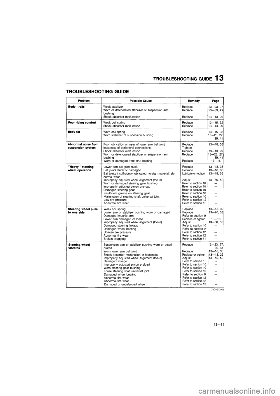
TROUBLESHOOTING GUIDE
Problem Possible Cause Remedy Page
Body "rolls" Weak stabilizer Replace 13-23, 27 Worn or deteriorated stabilizer or suspension arm Replace 13—39, 41 bushing
Shock absorber malfunction Replace 13-13, 29
Poor riding comfort Weak coil spring Replace 13-15, 32 Shock absorber malfunction Replace 13-13. 29
Body tilt Worn coil spring Replace 13-15, 32 Worn stabilizer of suspension bushing Replace 13-23, 27,
39, 41
Abnormal noise from Poor lubrication or wear of lower arm ball joint Replace 13-18, 36 suspension system looseness of peripheral connections Tighten
Shock absorber malfunction Replace 13-13, 29 Worn or deteriorated stabilizer or suspension arm Replace 13—23, 27, bushing 39, 41 Worn or damaged front strut bearing Replace 13-15
"Heavy" steering Lower arm ball joint stuck Replace 13—18, 36
wheel operation Ball joints stuck or damaged Replace 13-18, 36
Ball joints insufficiently lubricated; foreign material; ab-Lubricate or replace 13-18, 36
normal wear Improperly adjusted wheel alignment (toe-in) Adjust 13-50, 52
Worn or damaged steering gear bushing Refer to section 10 —
Improperly adjusted pinion pre-load Refer to section 10 —
Damaged steering gear Refer to section 10 —
Insufficient grease on steering gear Refer to section 10 —
Malfunction of steering shaft universal joint Refer to section 10 —
Low tire pressure Refer to section 12 —
Abnormal tire wear Refer to section 12 —
Steering wheel pulls Weak coil spring Replace 13-15, 32
to one side Lower arm or stabilizer bushing worn or damaged Replace 13-20, 38
Damaged knuckle arm Refer to section 9 —
Lower arm damaged or loose Replace or tighten 13-18 Improperly adjusted wheel alignment (toe-in) Adjust 13-50, 52
Damaged steering linkage Refer to section 10 —
Damaged wheel bearing Refer to section 9 —
Uneven tire pressure Refer to section 12 —
Abnormal tire wear Refer to section 12 —
Brakes dragging Refer to section 11 —
Steering wheel Suspension arm or stabilizer bushing worn or deteri-Replace 13—23, 27.
vibrates orated 39, 41
Worn lower arm ball joint Replace 13-18, 36
Shock absorber malfunction or looseness Replace or tighten 13-13, 29
Improperly adjusted wheel alignment (toe-in) Adjust 13-50, 52 Damaged linkage Refer to section 10
Improperly adjusted pinion preload Refer to section 10
Worn steering gear bushing Refer to section 10 —
Loose steering shaft universal joint Refer to section 10 —
Damaged wheel bearing Refer to section 9 —
Abnormal tire wear Refer to section 12 —
Abnormal tire wear Refer to section 12 —
Damaged or unbalanced wheel Refer to section 12 —
76G13X-009
13—11
Page 1509 of 1865
1 3 TROUBLESHOOTING GUIDE
Problem Possible Cause Remedy Page
Excessive steering wheel play
Worn or damaged lower arm bushing
Improperly adjusted pinion preload
Worn rack and pinion
Loose steering shaft universal joint
Replace
Refer to section 10
Refer to section 10
Refer to section 10
13-20, 38
General instability Weak coil springs
Shock absorber malfunction Worn or damaged lower arm or stabilizer bushing
Improperly adjusted wheel alignment Improperly adjusted pinion preload
Loose steering shaft universal joint Incorrect tire pressure Damaged or unbalanced wheel Malfunction of wheel bearing
Replace Replace Replace Adjust
Refer to section 10 Refer to section 10 Refer to section 12 Refer to section 12 Refer to section 9
13-15, 32
13-13, 29
13-20, 38
13-50, 52
76G13X-009
13-12
Page 1547 of 1865
1 3 FRONT WHEEL ALIGNMENT
FRONT WHEEL ALIGNMENT
86U13X-108
69G10X-031
Pre-inspection
1. Check the tire inflation and bring to the recom-
mended pressure.
2. Inspect the front wheel bearing play and correct,
it if necessary.
3. Inspect the wheel and tire runout.
4. Inspect the ball joints and steering linkage for any
excessive looseness.
5. The vehicle must be on level ground and have no
luggage or passenger load.
6. The difference in height between the left and right
sides from the center of the wheel to the fender
brim must be within 10 mm (0.39 in).
Caution
a) Front and rear wheel alignment should be
checked simultaneously. If adjustment is
made to either the front or rear wheels,
recheck the alignment, particularly toe-in,
on all other wheels.
b) Check and adjust the steering angle trans-
fer shaft after adjusting the front wheel
alignment. (Refer to Section 10)
TOE-IN
Inspection
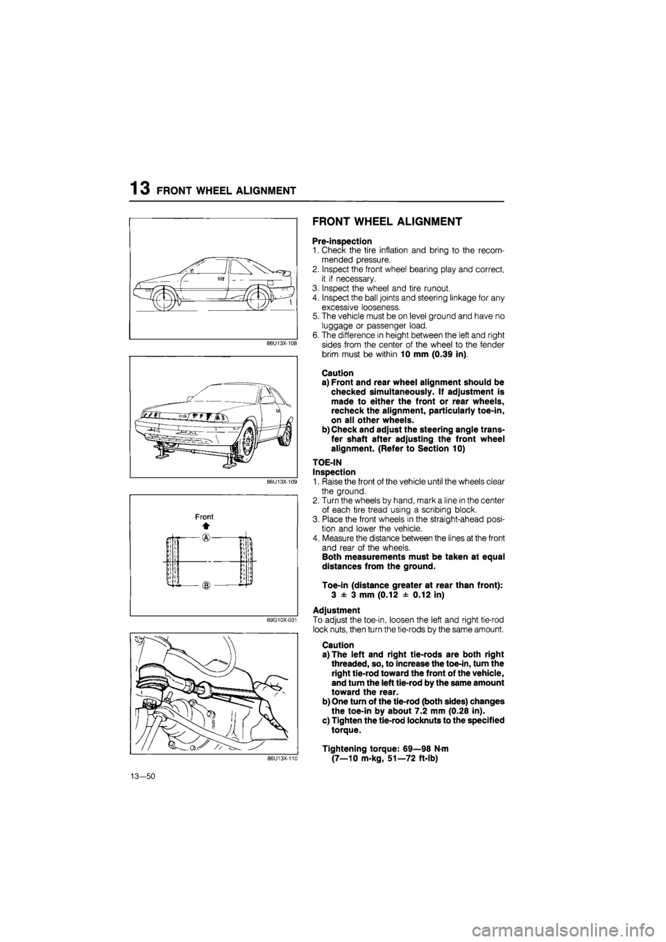
1. Raise the front of the vehicle until the wheels clear
the ground.
2. Turn the wheels by hand, mark a line in the center
of each tire tread using a scribing block.
3. Place the front wheels in the straight-ahead posi-
tion and lower the vehicle.
4. Measure the distance between the lines at the front
and rear of the wheels.
Both measurements must be taken at equal
distances from the ground.
Toe-in (distance greater at rear than front):
3 ± 3 mm (0.12 ± 0.12 in)
Adjustment
To adjust the toe-in, loosen the left and right tie-rod
lock nuts, then turn the tie-rods by the same amount.
Caution
a) The left and right tie-rods are both right
threaded, so, to increase the toe-in, turn the
right tie-rod toward the front of the vehicle,
and turn the left tie-rod by the same amount
toward the rear.
b) One turn of the tie-rod (both sides) changes
the toe-in by about 7.2 mm (0.28 in).
c) Tighten the tie-rod locknuts to the specified
torque.
Tightening torque: 69—98 N-m
(7—10 m-kg, 51—72 ft-lb) 86U13X-110
13-50
Page 1549 of 1865
13 REAR WHEEL ALIGNMENT
76G13X-033
86U13X-116
86U13X-117
86U13X-116
13-52
REAR WHEEL ALIGNMENT
PRE-INSPECTION
1. Check the tire inflation and bring to the recom-
mended pressure.
2. Inspect the wheel and tire runout.
3. The vehicle must be on level ground and have no
luggage or passenger load.
4. Check that the suspension is correctly adjusted.
5. The difference in height between the left and right
sides from the center of the wheel to the fender
rim should be within 10 mm (0.39 in).
Caution
a) Front and rear wheel alignments should be
checked simultaneously. If adjustment is
made to either the front or rear wheels,
recheck the alignment, particularly toe-in,
on all other wheels.
b) Check and adjust the steering angle trans-
fer shaft after adjusting the rear wheel align-
ment. (Refer to Section 10.)
TOE-IN
Inspection
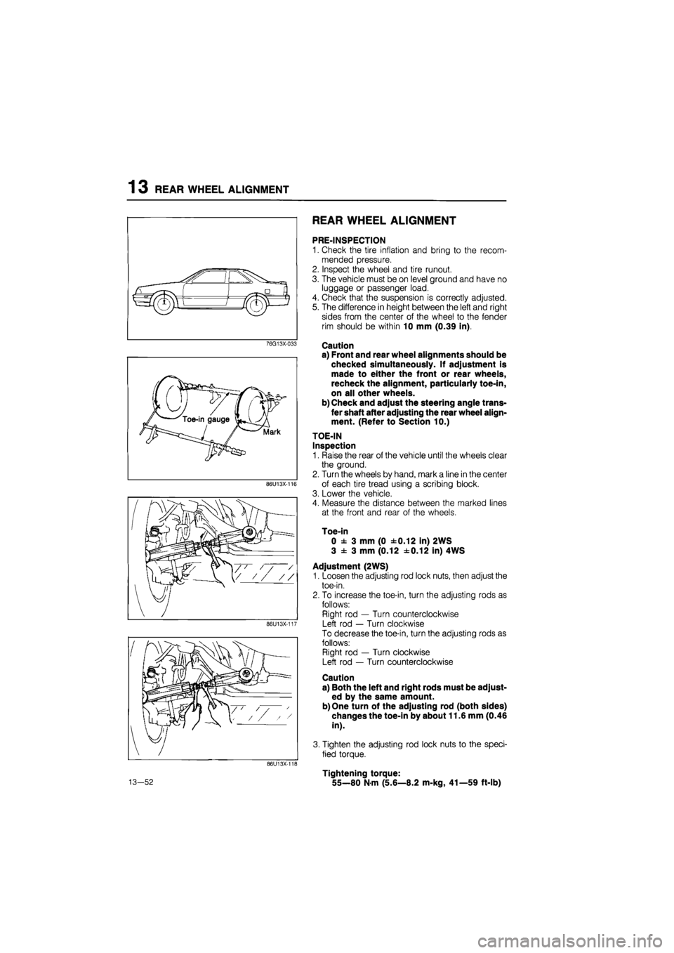
1. Raise the rear of the vehicle until the wheels clear
the ground.
2. Turn the wheels by hand, mark a line in the center
of each tire tread using a scribing block.
3. Lower the vehicle.
4. Measure the distance between the marked lines
at the front and rear of the wheels.
Toe-in
0 ± 3 mm (0 ±0.12 in) 2WS
3 ± 3 mm (0.12 ±0.12 in) 4WS
Adjustment (2WS)
1. Loosen the adjusting rod lock nuts, then adjust the
toe-in.
2. To increase the toe-in, turn the adjusting rods as
follows:
Right rod — Turn counterclockwise
Left rod — Turn clockwise
To decrease the toe-in, turn the adjusting rods as
follows:
Right rod — Turn clockwise
Left rod — Turn counterclockwise
Caution
a) Both the left and right rods must be adjust-
ed by the same amount.
b) One turn of the adjusting rod (both sides)
changes the toe-in by about 11.6 mm (0.46
in).
3. Tighten the adjusting rod lock nuts to the speci-
fied torque.
Tightening torque:
55—80 N-m (5.6—8.2 m-kg, 41—59 ft-lb)
Page 1582 of 1865
HEADLIGHT AND COMBINATION LIGHT 1 4
AIMING
Headlight
1. Adjust the tires to the standard pressure.
2. Position the vehicle on a flat level surface (unload-
ed condition).
86U14X-073
76G14X-009
14-31
Page 1601 of 1865
14 WINDSHIELD GLASS
Repair seal
Dam
_5 mm
.(0.19
11 mm
(0.43 in)
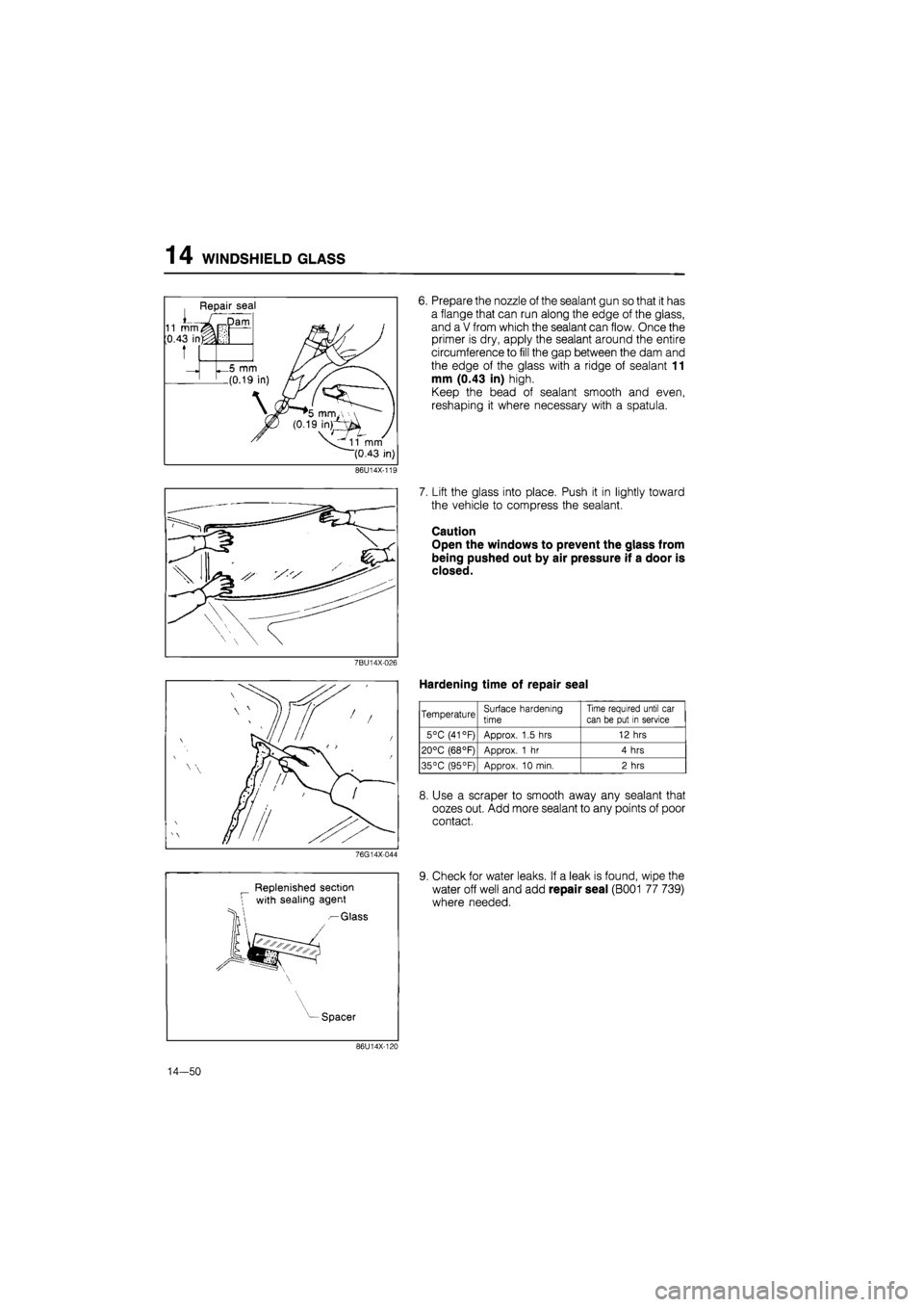
6. Prepare the nozzle of the sealant gun so that it has
a flange that can run along the edge of the glass,
and a V from which the sealant can flow. Once the
primer is dry, apply the sealant around the entire
circumference to fill the gap between the dam and
the edge of the glass with a ridge of sealant 11
mm (0.43 in) high.
Keep the bead of sealant smooth and even,
reshaping it where necessary with a spatula.
86U14X-11E
7BU14X-026
76G14X-044
Replenished section
with sealing agent
— Glass
7. Lift the glass into place. Push it in lightly toward
the vehicle to compress the sealant.
Caution
Open the windows to prevent the glass from
being pushed out by air pressure if a door is
closed.
Hardening time of repair seal
Temperature Surface hardening
time
Time required until car
can be put in service
5°C (41 °F) Approx. 1.5 hrs 12 hrs
20°C (68°F) Approx. 1 hr 4 hrs
35°C (95°F) Approx. 10 min. 2 hrs
8. Use a scraper to smooth away any sealant that
oozes out. Add more sealant to any points of poor
contact.
9. Check for water leaks. If a leak is found, wipe the
water off well and add repair seal (B001 77 739)
where needed.
Spacer
86U14X-120
14-50