1987 MAZDA 626 tire pressure
[x] Cancel search: tire pressurePage 1295 of 1865
TROUBLESHOOTING GUIDE 1 0
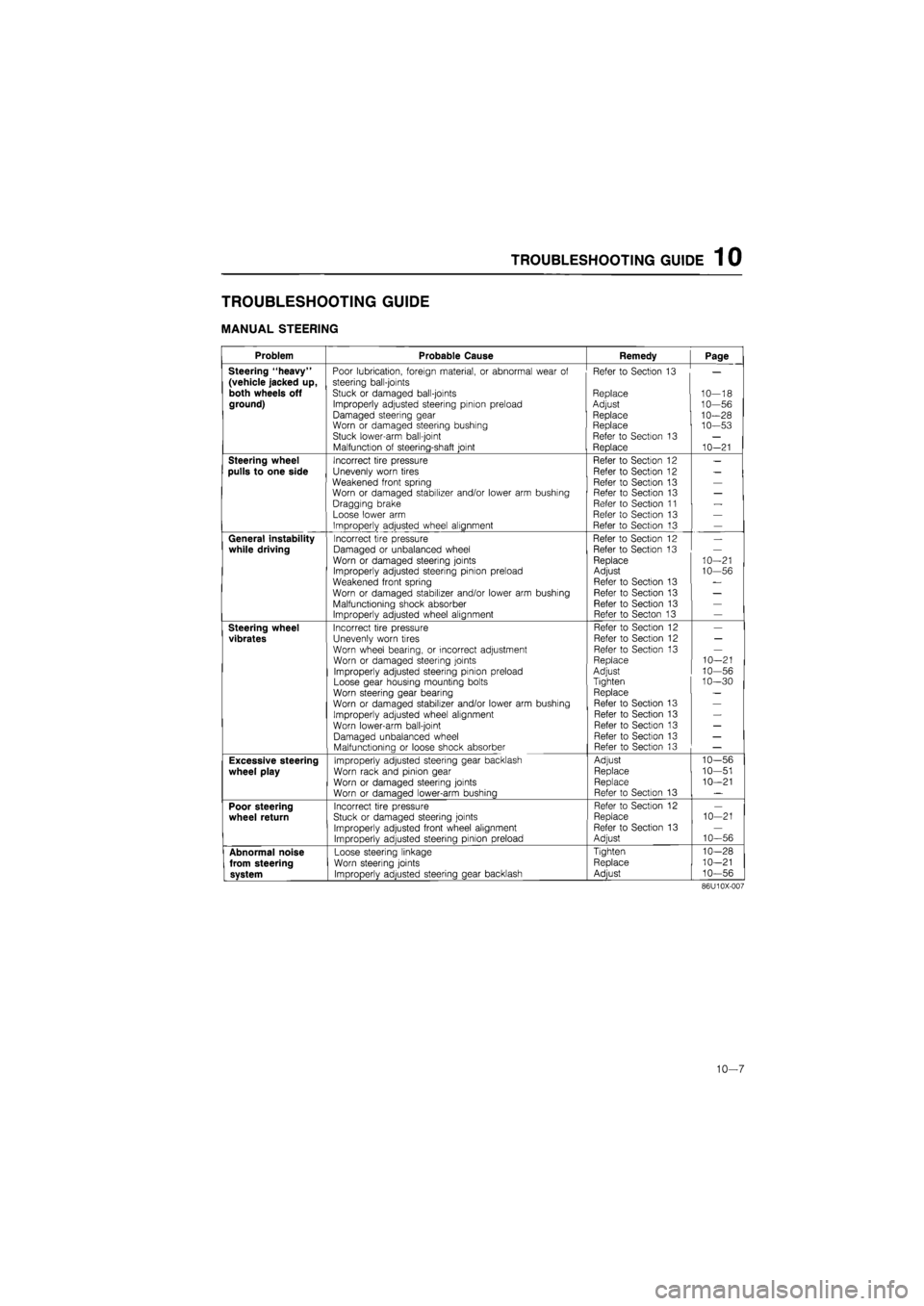
TROUBLESHOOTING GUIDE
MANUAL STEERING
Problem Probable Cause Remedy Page
Steering "heavy" Poor lubrication, foreign material, or abnormal wear of Refer to Section 13
(vehicle jacked up, steering bail-joints
both wheels off Stuck or damaged ball-joints Replace 10--18 ground) Improperly adjusted steering pinion preload Adjust 10--56
Damaged steering gear Replace 10--28 Worn or damaged steering bushing Replace 10--53 Stuck lower-arm ball-joint Refer to Section 13
Malfunction of steering-shaft joint Replace 10--21
Steering wheel Incorrect tire pressure Refer to Section 12
pulls to one side Unevenly worn tires Refer to Section 12
Weakened front spring Refer to Section 13 Worn or damaged stabilizer and/or lower arm bushing Refer to Section 13
Dragging brake Refer to Section 11
Loose lower arm Refer to Section 13
Improperly adjusted wheel alignment Refer to Section 13
General instability Incorrect tire pressure Refer to Section 12
while driving Damaged or unbalanced wheel Refer to Section 13
Worn or damaged steering joints Replace 10--21 Improperly adjusted steering pinion preload Adjust 10--56
Weakened front spring Refer to Section 13
Worn or damaged stabilizer and/or lower arm bushing Refer to Section 13
Malfunctioning shock absorber Refer to Section 13 Improperly adjusted wheel alignment Refer to Secton 13
Steering wheel Incorrect tire pressure Refer to Section 12
vibrates Unevenly worn tires Refer to Section 12
Worn wheel bearing, or incorrect adjustment Refer to Section 13
Worn or damaged steering joints Replace 10--21
Improperly adjusted steering pinion preload Adjust 10--56
Loose gear housing mounting bolts Tighten 10--30
Worn steering gear bearing Replace
Worn or damaged stabilizer and/or lower arm bushing Refer to Section 13
Improperly adjusted wheel alignment Refer to Section 13
Worn lower-arm ball-joint Refer to Section 13
Damaged unbalanced wheel Refer to Section 13
Malfunctionina or loose shock absorber Refer to Section 13
Excessive steering Improperly adjusted steering gear backlash Adjust 10--56
wheel play Worn rack and pinion gear Replace 10--51
Worn or damaged steering joints Replace 10--21
Worn or damaaed lower-arm bushinq Refer to Section 13
Poor steering Incorrect tire pressure Refer to Section 12
wheel return Stuck or damaged steering joints Replace 10 -21
Improperly adjusted front wheel alignment Refer to Section 13
Improperly adjusted steering pinion preload Adjust 10--56
Abnormal noise Loose steering linkage Tighten 10--28
from steering Worn steering joints Replace 10--21
system ImDroDerlv adiusted steerina aear backlash Adiust 10--56
86U10X-007
10—7
Page 1296 of 1865

1 0 TROUBLESHOOTING GUIDE
POWER STEERING
Problem Possible cause Remedy Page
Hard steering
Loose
or
damaged belt Low fluid level,
or air in
fluid Leakage
of
fluid
Malfunctioning electrical system* Insufficient oil pump pressure Improperly adjusted wheel alignment Malfunctioning steering gear Linkage ball joint not operating smoothly
Adjust
or
replace Add fluid
or
bleed
air
Repair
or
replace Repair
or
replace Repair
or
replace Refer
to
Section
13
Repair
or
replace Replace
10—12 10-11 10-13 10-87 10-16
10—28,
37
10-18
Poor return
Insufficient tire pressure
Improperly adjusted wheel alignment
Ball-joint not operating smoothly
Steering shaft contacting something
Refer
to
Section
12
Refer
to
Section
13
Replace
Repair
10-20 10-21
Excessive play
Loose gear box housing mounting bolts Worn linkage
or
tie-rod ball joint Worn lower ball joint Worn
or
damaged steering joint Worn rack and pinion gear
Tighten Replace
Refer
to
Section
13
Replace
Replace
10—30
10—18
10—21
10-58,
75
Steering wheel
vibrates
Insufficient tire pressure Damaged
or
unbalanced wheel Improperly adjusted wheel alignment Loose gear box housing mounting bolts Incorrect pinion preload adjustment Worn ball joints
Loose shock absorber mounting Malfunctioning shock absorber
Refer
to
Section
12
Refer
to
Section
13
Refer
to
Section
13
Tighten Adjust
Replace Refer
to
Section
13
Refer
to
Section
13
10-30 10-72,
81
10—18
Steering wheel
pulls
Unevenly worn tires
Incorrect tire pressure
Dragging brake
Improperly adjusted wheel alignment
Refer
to
Section
12
Refer
to
Section
12
Refer
to
Section
11
Refer
to
Section
13 —
Excessively light
steering at high
speed*
Malfunctioning electrical system Repair
or
replace 10-87
*... Only
for
electronically
-
controlled type
76G10X-002
10—8
Page 1299 of 1865
ON-VEHICLE MAINTENANCE 1 0
"{krf
'"""^JlW^M 1
V
^A-X
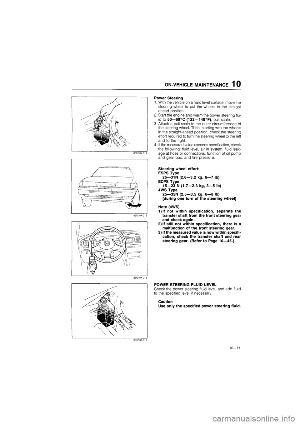
Power Steering
1.
86U10X-014
86U10X-015
With the vehicle on a hard level surface, move the
steering wheel to put the wheels in the straight
ahead position.
Start the engine and warm the power steering flu-
id to 50—60°C (122—140°F), pull scale.
Attach a pull scale to the outer circumference of
the steering wheel. Then, starting with the wheels
in the straight-ahead position, check the steering
effort required to turn the steering wheel to the left
and to the right.
If the measured value exceeds specification, check
the following: fluid level, air in system, fluid leak-
age at hose or connections, function of oil pump
and gear box, and tire pressure.
Steering wheel effort:
ESPS Type
25—31N (2.6—3.2 kg, 6—7 lb)
ECPS Type
15—23 N (1.7—2.3 kg, 3—5 lb)
4WS Type
25—35N (2.5—3.5 kg, 6—8 lb)
[during one turn of the steering wheel]
Note (4WS)
1)lf not within specification, separate the
transfer shaft from the front steering gear
and check again.
2) If still not within specification, there is a
malfunction of the front steering gear.
3) If the measured value is now within specifi-
cation, check the transfer shaft and rear
steering gear. (Refer to Page 10—45.)
86U10X-016
POWER STEERING FLUID LEVEL
Check the power steering fluid level, and add fluid
to the specified level if necessary.
Caution
Use only the specified power steering fluid.
86U10X-017
10—11
Page 1321 of 1865
4-WHEEL STEERING GEAR AND LINKAGE 1 0
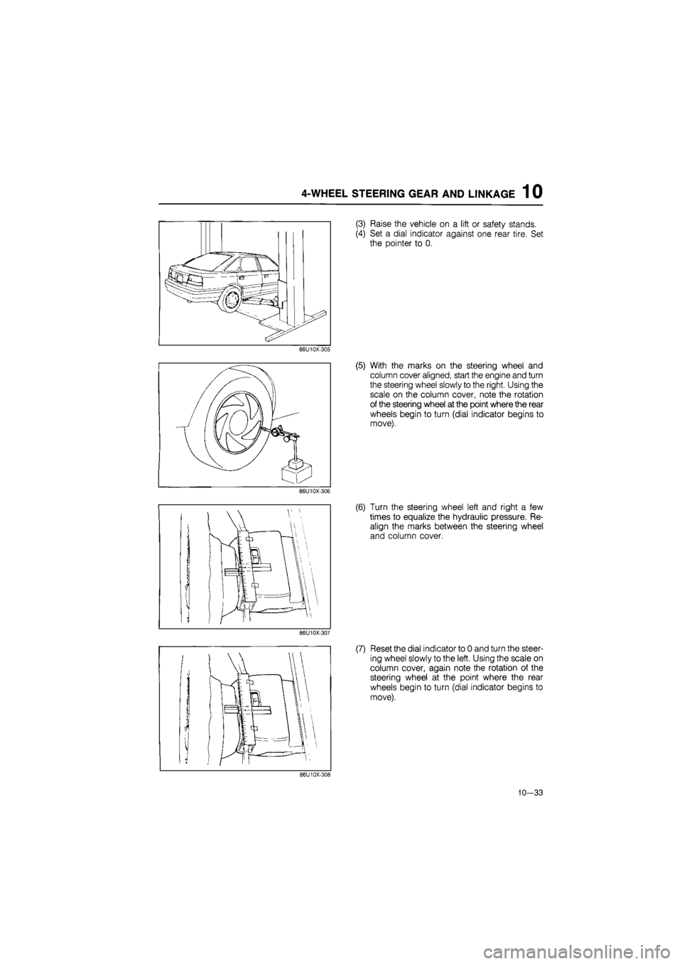
(3) Raise the vehicle on a lift or safety stands.
(4) Set a dial indicator against one rear tire. Set
the pointer to 0.
86U10X-305
(5) With the marks on the steering wheel and
column cover aligned, start the engine and turn
the steering wheel slowly to the right. Using the
scale on the column cover, note the rotation
of the steering wheel at the point where the rear
wheels begin to turn (dial indicator begins to
move).
86U10X-306
(6) Turn the steering wheel left and right a few
times to equalize the hydraulic pressure. Re-
align the marks between the steering wheel
and column cover.
86U10X-307
(7) Reset the dial indicator to 0 and turn the steer-
ing wheel slowly to the left. Using the scale on
column cover, again note the rotation of the
steering wheel at the point where the rear
wheels begin to turn (dial indicator begins to
move).
86U10X-308
10-33
Page 1397 of 1865
TROUBLESHOOTING GUIDE 1 1
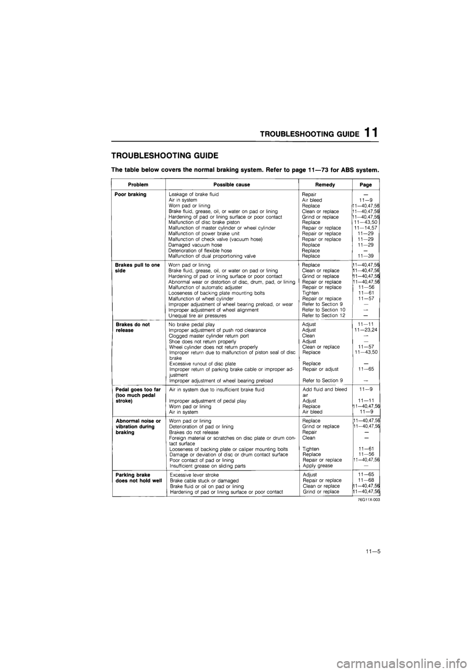
TROUBLESHOOTING GUIDE
The table below covers the normal braking system. Refer to page 11—73 for ABS system.
Problem Possible cause Remedy Page
Poor braking Leakage of brake fluid Air in system Worn pad or lining
Brake fluid, grease, oil, or water on pad or lining Hardening of pad or lining surface or poor contact Malfunction of disc brake piston Malfunction of master cylinder or wheel cylinder Malfunction of power brake unit
Malfunction of check valve (vacuum hose)
Damaged vacuum hose Deterioration of flexible hose Malfunction of dual proportioning valve
Repair Air bleed Replace
Clean or replace Grind or replace Replace Repair or replace Repair or replace Repair or replace Replace Replace Replace
11-9 11-40,47,56 11-40,47,56 11-40,47,56 11—43,50 11-14,57 11-29 11-29 11-29
11-39
Brakes pull to one
side
Worn pad or lining
Brake fluid, grease, oil, or water on pad or lining Hardening of pad or lining surface or poor contact Abnormal wear or distortion of disc, drum, pad, or lining Malfunction of automatic adjuster Looseness of backing plate mounting bolts Malfunction of wheel cylinder
Improper adjustment of wheel bearing preload, or wear Improper adjustment of wheel alignment Unequal tire air pressures
Replace Clean or replace Grind or replace Repair or replace Repair or replace Tighten
Repair or replace Refer to Section 9 Refer to Section 10 Refer to Section 12
11-40,47,56 11-40,47,56 11-40,47,56 11-40,47,56 11-56 11-61 11-57
Brakes do not
release
No brake pedal play
Improper adjustment of push rod clearance
Clogged master cylinder return port Shoe does not return properly Wheel cylinder does not return properly Improper return due to malfunction of piston seal of disc brake Excessive runout of disc plate Improper return of parking brake cable or improper ad-justment
Improper adjustment of wheel bearing preload
Adjust
Adjust
Clean
Adjust Clean or replace Replace
Replace Repair or adjust
Refer to Section 9
11-11
11—23,24
11-57 11—43,50
11-65
Pedal goes too far (too much pedal stroke)
Air in system due to insufficient brake fluid
Improper adjustment of pedal play Worn pad or lining Air in system
Add fluid and bleed air
Adjust Replace Air bleed
11—9
11—11 11-40,47,56 11-9
Abnormal noise or
vibration during
braking
Worn pad or lining Deterioration of pad or lining Brakes do not release
Foreign material or scratches on disc plate or drum con-tact surface
Looseness of backing plate or caliper mounting bolts Damage or deviation of disc or drum contact surface Poor contact of pad or lining Insufficient grease on sliding parts
Replace
Grind or replace
Repair
Clean
Tighten Replace Repair or replace Apply grease
11-40,47,56 11-40,47,56
11-61 11-56 11-40,47,56
Parking brake
does not hold well
Excessive lever stroke
Brake cable stuck or damaged
Brake fluid or oil on pad or lining Hardening of pad or lining surface or poor contact
Adjust
Repair or replace Clean or replace Grind or replace
11-65
11-68
11-40,47,56
11-40,47,56
76G11X-003
11—5
Page 1465 of 1865
ANTI-LOCK BRAKE SYSTEM (ABS) 1 1
TROUBLESHOOTING
Precaution
Conditions that are not malfunctions
1. It may happen that vibration is felt in the steering wheel, body, and/or brake pedal when the ABS
is functioning; such vibration is simply an indication that the system is functioning.
2. Sound of the pump motor operating, accumulator pressure being released, or the relay operating
may be heard from the engine compartment when the engine is started as the system is being auto-
matically checked.
3. The ABS pump motor may be automatically activated even though the ABS is not operating.
4. The ABS warning light may illuminate under any of the following conditions:
• When the vehicle is traveling on snow or ice with the parking brake activated or a brake dragging
at one wheel.
• When different-sized tires are used.
• When tires of different gripping performance are used.
• When (while the vehicle is jacked up or stuck) only the front wheels are spun for 20 seconds or more.
• When there is insufficient battery voltage.
Note
Under the above conditions, the warning light will not illuminate a second time when the
ignition is switched OFF then back ON, and there will be no memory entry to the control
unit of a problem.
Troubleshooting notes
The ABS is composed of electrical components, mechanical components (hydraulic unit), and the com-
ponents of the standard brake system.
Fundamentally, malfunction of the ABS electrical or mechanical components is judged by the self-
diagnosis function within the ABS control unit. And malfunctions are indicated by the warning light
in the instrument panel.
The location
of
a malfunction is indicated by the technician switching the system to the diagnosis-indication
mode.
The self-diagnosis and indication functions must be used when malfunctions of the ABS are being
diagnosed.
76G11X-091
11—73
Page 1493 of 1865
1 2 OUTLINE, TROUBLESHOOTING GUIDE
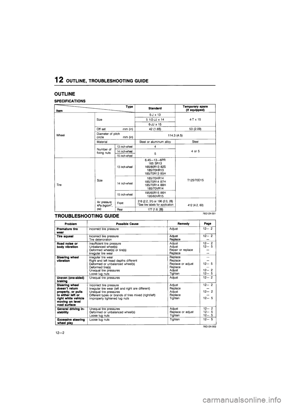
OUTLINE
SPECIFICATIONS
Type
Item Standard Temporary spare (if equipped)
Wheel
Size
5-J
x 13
4-T
x 15
Wheel
Size 5 1/2-JJ
x 14
4-T
x 15
Wheel
Size
6-JJ
x 15
4-T
x 15
Wheel
Off set mm (in) 42 (1.65) 53 (2.09)
Wheel Diameter
of
pitch circle
mm
(in) 114.3 (4.5) Wheel
Material Steel
or
aluminum alloy Steel
Wheel
Number
of
fixing nuts
13 inch-wheel 4
4
or 5
Wheel
Number
of
fixing nuts 14 inch-wheel 5 4
or 5
Wheel
Number
of
fixing nuts 15 inch-wheel 5 4
or 5
Tire
Size
13 inch-wheel
6.45—13—6PR
165 SR13 165/80R13 82S 185/70HR13 185/70R13 85H
T125/70D15
Tire
Size 14 inch-wheel
185/70HR14 185/70R14 87H 185/70R14 88H 185/70VR14
T125/70D15
Tire
Size
15 inch-wheel 195/60R15 86H
195/60VR15
T125/70D15
Tire
Air pressure
kPa (kg/cm2,
psi)
Front 216 (2.2, 31) or 196 (2.0, 28) "See tire labels for application 412(4.2, 60)
Tire
Air pressure
kPa (kg/cm2,
psi) Rear 177 (1.8, 26)
412(4.2, 60)
TROUBLESHOOTING GUIDE 76G12X-001
Problem Possible Cause Remedy Page
Premature tire wear
Incorrect tire pressure Adjust 12-
2
Tire squeal
Incorrect tire pressure Tire deterioration
Adjust ReDlace
12-
2
Road noise or body vibration
Insufficient tire pressure Unbalanced wheel(s) Deformed wheel(s)
or
tire(s) Irregular tire wear
Adjust Adjust Repair
or
replace Reolace
-1
12-
2
12-
5
Steering wheel vibration
Irregular tire wear Right and left tread depths different Deformed
or
unbalanced wheel(s) Deformed tire(s) Unequal tire pressures Loose lug nuts
Replace Replace
Replace
or
adjust Replace Adjust Tiahten
12-
5
12—
2
12-
5
Uneven (one-sided) braking
Unequal tire pressures Adjust 12-
2
Steering wheel doesn't return properly, or pulls to either left or right while vehicle moving on level road surface
Incorrect tire pressure Irregular tire wear (left and right are different) Unequal tire pressures Different types
or
brands
of
tires mixed (right/left) Improperly tightened lug nuts
Adjust Replace Adjust Replace Tighten
12-
2
12—
2
12-
5
General driving in-stability
Unequal tire pressures Deformed
or
unbalanced wheel(s) Loose lug nuts
Adjust Replace
or
adjust Tiahten
12-
2
12-
5
12-
5
Excessive steering wheel play
Loose lug nuts Tighten 12-
5
76G12X-002
12-2
Page 1494 of 1865
WHEELS AND TIRES 1 2
86U12X-004
\k
y
i jYj
/ <4/
/ v Wear platform
Wear indicators
86U12X-005
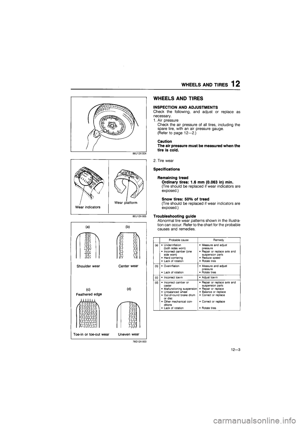
(a) (b)
Shoulder wear Center wear
(c)
Feathered edge
(d)
*f tftiit t
Toe-in or toe-out wear Uneven wear
WHEELS AND TIRES
INSPECTION AND ADJUSTMENTS
Check the following, and adjust or replace as
necessary.
1. Air pressure
Check the air pressure of all tires, including the
spare tire, with an air pressure gauge.
(Refer to page 12—2.)
Caution
The air pressure must be measured when the
tire is cold.
2. Tire wear
Specifications
Remaining tread
Ordinary tires: 1.6 mm (0.063 in) min.
(Tire should be replaced if wear indicators are
exposed.)
Snow tires: 50% of tread
(Tire should be replaced if wear indicators are
exposed.)
Troubleshooting guide
Abnormal tire wear patterns shown in the illustra-
tion can occur. Refer to the chart for the probable
causes and remedies.
Probable cause Remedy
(a) • Underinflation (both sides worn) • Incorrect camber (one side worn) • Hard cornering • Lack of rotation
• Measure and adjust pressure • Repair or replace axle and suspension parts • Reduce speed • Rotate tires
(b) • Overinflation
• Lack of rotation
• Measure and adjust pressure • Rotate tires
(c) • Incorrect toe-in • Adjust toe-in
(d) • Incorrect camber or caster • Malfunctioning suspension • Unbalanced wheel • Out-of-round brake drum or disc • Other mechanical con-ditions • Lack of rotation
• Repair or replace axle and suspension parts • Repair or replace • Balance or replace • Correct or replace
• Correct or replace
• Rotate tires
76G12X-003
12-3