1987 MAZDA 626 parking brake
[x] Cancel search: parking brakePage 10 of 1865
G TOWING
76GOGX-OQ2
i-^C.
y -
- r^jfftj&H
r —I
76UQGX-003
86U0GX-004
G—8
TOWING
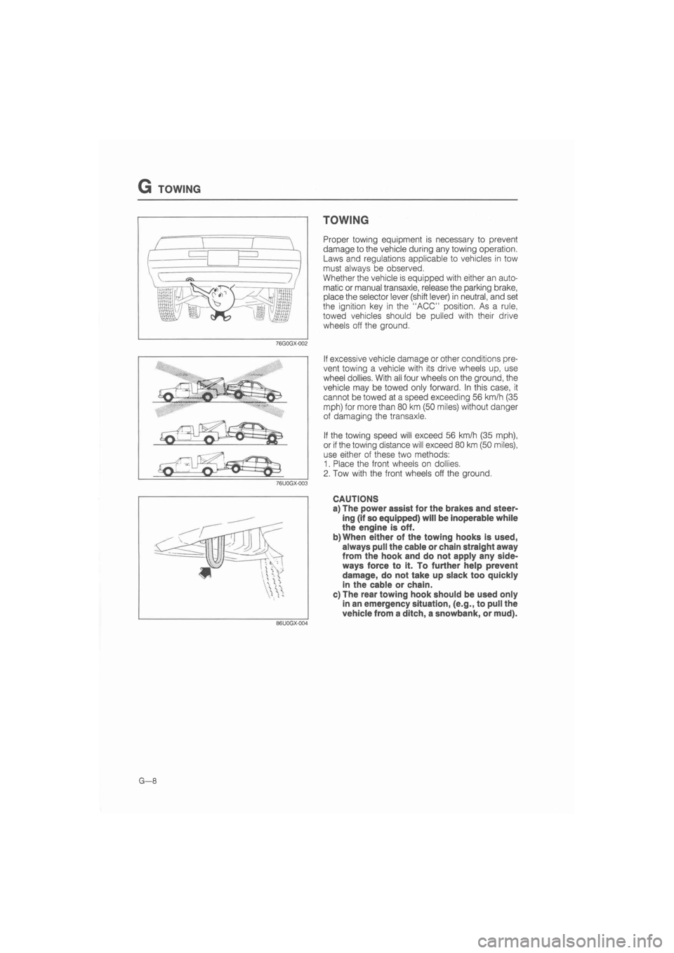
Proper towing equipment is necessary to prevent
damage to the vehicle during any towing operation.
Laws and regulations applicable to vehicles in tow
must always be observed.
Whether the vehicle is equipped with either an auto-
matic or manual transaxle, release the parking brake,
place the selector lever (shift lever) in neutral, and set
the ignition key in the "ACC" position. As a rule,
towed vehicles should be pulled with their drive
wheels off the ground.
If excessive vehicle damage or other conditions pre-
vent towing a vehicle with its drive wheels up, use
wheel dollies. With all four wheels on the ground, the
vehicle may be towed only forward. In this case, it
cannot be towed at a speed exceeding 56 km/h (35
mph) for more than 80 km (50 miles) without danger
of damaging the transaxle.
If the towing speed will exceed 56 km/h (35 mph),
or if the towing distance will exceed 80 km (50 miles),
use either of these two methods:
1. Place the front wheels on dollies.
2. Tow with the front wheels off the ground.
CAUTIONS
a) The power assist for the brakes and steer-
ing (if so equipped) will be inoperable while
the engine is off.
b)When either of the towing hooks is used,
always pull the cable or chain straight away
from the hook and do not apply any side-
ways force to it. To further help prevent
damage, do not take up slack too quickly
in the cable or chain.
c) The rear towing hook should be used only
in an emergency situation, (e.g., to pull the
vehicle from a ditch, a snowbank, or mud).
Page 14 of 1865
0 PRE-DELIVERY INSPECTION
PRE-DELIVERY INSPECTION TABLE
EXTERIOR
INSPECT and ADJUST, if necessary, the following items
to the specifications:
• Glass, exterior bright metal and paint for damage
• Wheel lug nuts
88—118 N m (9—12 m-kg, 65—87 ft-lb)
• Tire pressures (Refer to section 12)
• All weatherstrips for damage or detachment
• Operation of bonnet release and lock
• Operation of fuel lid and trunk lid (Back door) opener
• Door operation and alignment
• Headlight aiming
INSTALL following parts:
• Wheel caps or rings (if equipped)
• Outside rear view mirror(s)
UNDER BONNET—ENGINE OFF
INSPECT and ADJUST, if necessary, the following items
to the specifications:
• Fuel, coolant and hydraulic lines, fittings, connections and
components for leaks
• Engine oil level
• Power steering fluid level (if equipped)
• Brake and clutch master cylinder fluid level (if equipped)
• Windshield washer reservoir fluid level
• Radiator coolant level and specific gravity
Protection °C (°F) Specific gravity at 20°C (68°F)
-4 (25) 1.028
-16(3) 1.054
-26 (-15) 1.066 -40 (-40) 1.078
• Tightness of water hose clamps (including heater hoses)
• Tightness of battery terminals
• Manual transaxle oil level
• Drive belt tensions (Refer to section 1)
• Accelerator cable and its linkage for free movement
• Headlight cleaner fluid level (if equipped)
CLEAN spark plugs
INTERIOR
INSTALL the following parts:
• Rubber stopper for inside rear view mirror
• Fuse for accessories
CHECK the operations of the following items:
• Seat controls (sliding and reclining) and head rest
• Door locks including childproof door locks (if equipped)
• Seat belts and warning system
• Ignition switch and steering lock
• Inhibitor switch (ATX only)
• All lights including warning and indicator lights
• Sound warning system
• Headlight cleaner (if equipped)
• Horn, wipers and washers (front and rear, if equipped)
• Radio and antenna (if equipped)
• Cigarette lighter and clock
• Remote control outside rear view mirrors (if equipped)
• Power windows (if equipped)
• Heater, defroster and air conditioner at various mode
selection (if equipped)
• Sunroof (if equipped)
ADJUST antenna trimmer on radio (if equipped)
CHECK the following items:
• Presence of spare fuse
• Upholstery and interior finish
CHECK and ADJUST, if necessary, the following items:
• Operation and fit of windows
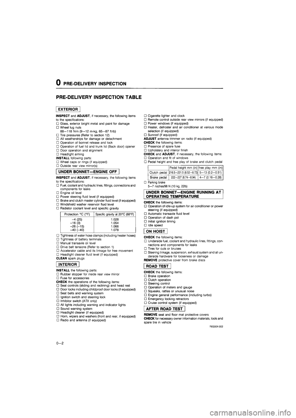
• Pedal height and free play of brake and clutch pedal
Pedal height mm (in) free play mm (in)
Clutch pedal 216.5-221.5 (8.52-8.72) 5-13 (0.2-0.51)
Brake pedal 222-227 (8.74-8.94) 4-7 (0.16-0.28)
• Parking brake
5-7 noches/98 N (10 kg, 22lb)
UNDER BONNET—ENGINE RUNNING AT
OPERATING TEMPERATURE
CHECK the following items:
• Operation of idle-up system for air conditioner or power
steering (if equipped)
• Automatic transaxle fluid level
• Operation of dash pot
• Initial ignition timing
• Idle speed
ON HOIST
CHECK the following items:
• Underside fuel, coolant and hydraulic lines, fittings, con-
nections and components for leaks
• Tires for cuts or bruises
• Steering linkage, suspension, exhaust system and all un-
derside hardware for looseness or damage
REMOVE protective cover from brake discs
ROAD TEST"
CHECK the following items:
• Brake operation
• Clutch operation
• Steering control
• Operation of meters and gauge
• Squeaks, rattles or unusual noise
• Engine general performance (including turbo)
• Emergency locking retractors
• Cruise control system (if equipped)
AFTER ROAD TEST
REMOVE seat and floor mat protective covers
CHECK for necessary owner information materials, tools and
spare tire in vehicle
-76G00X-002
0-2
Page 16 of 1865

0 1 Interval
Procedure & item
Number of Months or km, whichever corns first
©1 ©2 ©3 ©4 Service data and inspection point Page
Interval
Procedure & item
Months — 6 12 18 24 30 36 42 48 ©1 ©2 ©3 ©4 Service data and inspection point Page
Interval
Procedure & item
x 1000 Km 1 10 20 30 40 50 60 70 80 ©1 ©2 ©3 ©4 Service data and inspection point Page
Interval
Procedure & item
Miles x
1000 0.6 6 12 18 24 30 36 42 48
©1 ©2 ©3 ©4 Service data and inspection point Page
Clutch pedal I 1 I I I I I I O O o o
• Operation
• Pedal height: 216.5—221.5 mm
(8.524—8.720 in) • Free play: 5—13 mm (0.20-0.51 in)
6-4
Brake pedal I 1 I I I I I I O o o o
• Operation
• Pedal height: 222—227 mm (8.74-8.94 in)
• Free play: 4—7 mm (0.16—0.28 in)
11—11
11—11
Parking brake A A A A o o o o
• Operation
• Lever stroke:
5—7 notches
11—65
Power brake unit and hoses 1 I I I o o o o • Operation • Check the vacuum hoses and con-nectors
11—27
Brake fluid " I 1 I R I I I R o o o o • Fluid level 11-6
Clutch fluid I 1 I I I I I I o o o o • Fluid level 6—4
Power steering fluid I 1 I I I I I I
I
o
o"
o
o
o o • Fluid level 10—11
Power steering system and hoses 1 I I
I I
I
o
o"
o
o o o • Fluid leakage or oozing 10—13
Air cleaner element *3 1 R I R —
1A—6 1B—5 1C—5
Choke system 1 I I o o X X
• Carburetor linkage • Choke diaphragm • Choke valve clearance
• Choke Unloader system
4A-26 4A—34 4A—34 4A—33
Cooling system (including coolant level adjustment) 1 I I I o o o o • Hoses for cracks or wear
• Coolant level
3A—5 3B—4
Engine coolant Replace every 2 years o o o o -3A-5 3B-4
Page 22 of 1865
0
1
o
interval
Procedure & Item
Number of Months or km, whichever corns first
©1 ©2 ©3 ©4 Service data and inspection point Page
interval
Procedure & Item
Months — 6 12 18 24 30 36 42 48 ©1 ©2 ©3 ©4 Service data and inspection point Page
interval
Procedure & Item
x
1000 Km
1 10 20 30 40 50 60 70 80 ©1 ©2 ©3 ©4 Service data and inspection point Page
interval
Procedure & Item
Miles x 1000
0.6 6 12 18 24 30 36 42 48
©1 ©2 ©3 ©4 Service data and inspection point Page
Clutch pedal I I I I I I I I O o o o
• Operation
• Pedal height: 216.5—221.5 mm (8.524—8.720 in)
• Free play: 5—13 mm (0.20—0.51 in)
6-4
Brake pedal I I I I I I I I O o o o
• Operation • Pedal height: 222—227 mm (8.74—8.94 in)
• Free play: 4—7 mm (0.16—0.28 in)
11-11
11—11
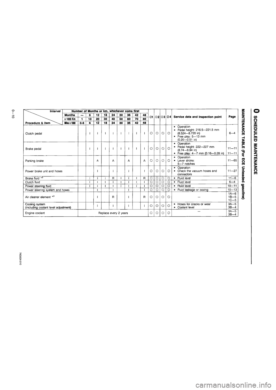
Parking brake A A A A o o o o
• Operation • Lever stroke: 5—7 notches
11-65
Power brake unit and hoses I I I I o o o o
• Operation • Check the vacuum hoses and connectors
11—27
Brake fluid *5 I I I R I I I R 0 o o o • Fluid level 11—6
Clutch fluid I I I I I I I I o o o 0 • Fluid level 6-4
Power steering fluid I I I I I I I I o o o o • Fluid level 10—11
Power steering system and hoses I I I I 0 o o 0 • Fluid leakage or oozing 10—13
Air cleaner element *3 I R I R o o o o —
1 A—6 1B—5 1C-5
Cooling system (including coolant level adjustment) I I I I o o o o • Hoses for cracks or wear • Coolant level
3A—5
3B-4
Engine coolant Replace every 2 years 0 o 0 0 — 3A-5 3B—4
a> a o o X o o
Page 28 of 1865
0 1
CO
interval Number of Months or km, whichever corns first
Months — 6 12 18 24 30 36 42 48 ©1 ©2 ©3 ©4 Service data and inspection point Page x 1000 Km 1 10 20 30 40 50 60 70 80 ©1 ©2 ©3 ©4 Service data and inspection point Page
Procedure & item Miles x 1000 0.6 6 12 18 24 30 36 42 48
Clutch pedal I I I I I I I I O o o o
• Operation • Pedal height: 216.5—221.5 mm (8.524—8.720 in) • Free play: 5—13 mm (0.20—0.51 in)
6—4
Brake pedal I I I I I I I I o o o o
• Operation
• Pedal height: 222—227 mm (8.74—8.94 in)
• Free play: 4—7 mm (0.16—0.28 in)
11-11
11—11
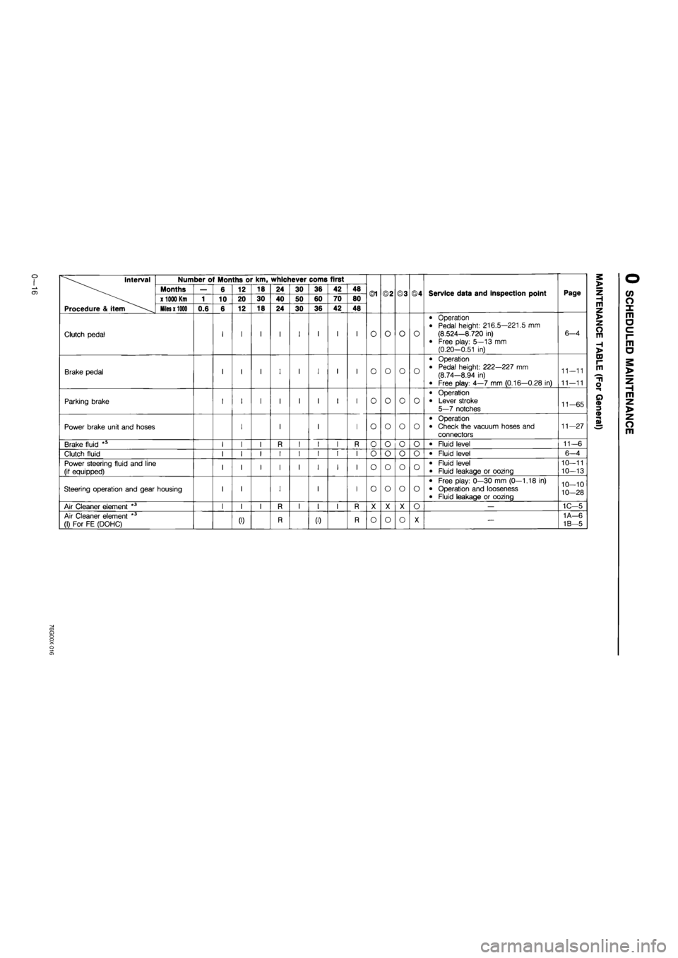
Parking brake I I I I I I I I o o o o
• Operation • Lever stroke 5—7 notches 11-65
Power brake unit and hoses I I I I o o o o
• Operation • Check the vacuum hoses and connectors
11—27
Brake fluid *s I I I R I I I R o o o o • Fluid level 11-6
Clutch fluid I I I I I I I I o o o o • Fluid level 6-4
Power steering fluid and line (if equipped) I I I I I I I I o o o o • Fluid level • Fluid leakage or oozing
10—11
10—13
Steering operation and gear housing I I I I I o o o o
• Free play: 0—30 mm (0—1.18 in) • Operation and looseness • Fluid leakage or oozing
10—10
10-28
Air Cleaner element *3 I I I R I I I R X X X o — 1C—5
Air Cleaner element *3 (1) For FE (DOHC) (0 R (I) R o o o X — 1A—6
1B—5
Page 871 of 1865
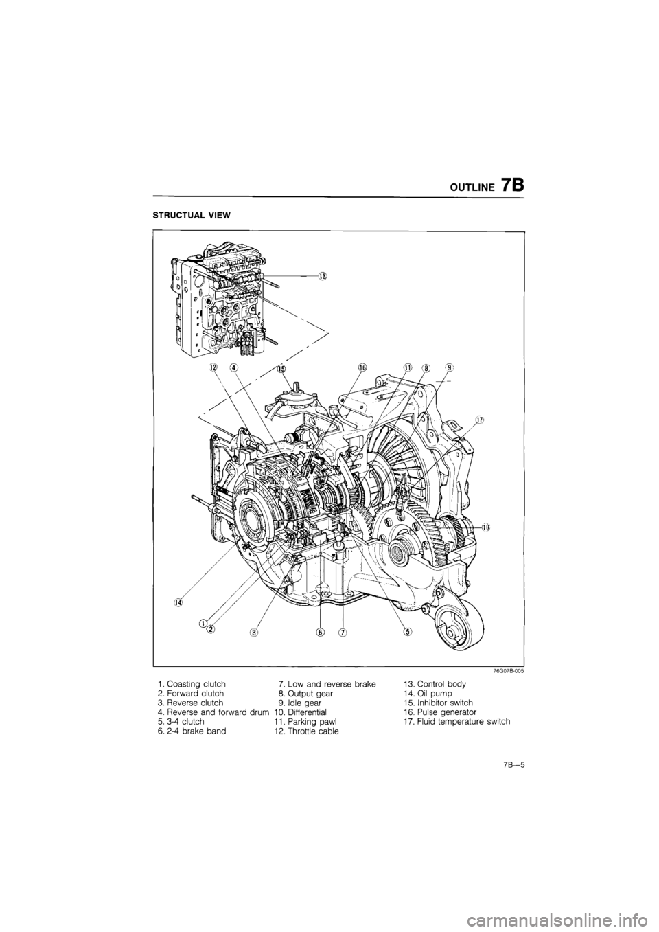
OUTLINE 7B
STRUCTUAL VIEW
76G07B-005
1. Coasting clutch 7. Low and reverse brake
2. Forward clutch 8. Output gear
3. Reverse clutch 9. Idle gear
4. Reverse and forward drum 10. Differential
5. 3-4 clutch 11. Parking pawl
6. 2-4 brake band 12. Throttle cable
13. Control body
14. Oil pump
15. Inhibitor switch
16. Pulse generator
17. Fluid temperature switch
7B—5
Page 889 of 1865
TROUBLESHOOTING (G4A-EL) 7B
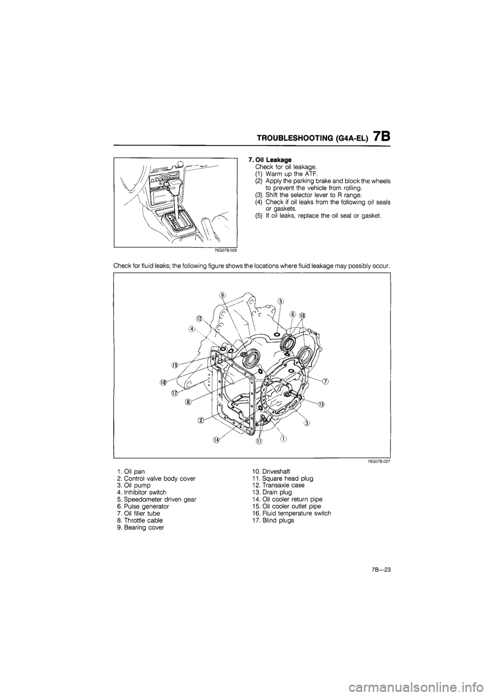
7. Oil Leakage
Check for oil leakage.
(1) Warm up the ATF.
(2) Apply the parking brake and block the wheels
to prevent the vehicle from rolling.
(3) Shift the selector lever to R range.
(4) Check if oil leaks from the following oil seals
or gaskets.
(5) If oil leaks, replace the oil seal or gasket.
76G07B-026
Check for fluid leaks; the following figure shows the locations where fluid leakage may possibly occur.
1. Oil pan
2. Control valve body cover
3. Oil pump
4. Inhibitor switch
5. Speedometer driven gear
6. Pulse generator
7. Oil filler tube
8. Throttle cable
9. Bearing cover
10. Driveshaft
11. Square head plug
12. Transaxle case
13. Drain plug
14. Oil cooler return pipe
15. Oil cooler outlet pipe
16. Fluid temperature switch
17. Blind plugs
76G07B-027
7B—23
Page 893 of 1865

TROUBLESHOOTING (G4A-EL) 7B
STEP 4 (STALL TEST)
This step is performed to determine if there is slippage of the friction elements or malfunction of the
hydraulic components.
Preparation
Check the following items prior to testing:
1. Engine coolant, engine oil and ATF levels.
2. Warm the engine thoroughly to raise the ATF temperature to operating level (50—80°C, 122—176°F).
3. Engage the parking brake and use wheel chocks at the front and rear wheels.
Pull the parking brake Water temperature
ATF
79G07C-084
7B-27