Page 894 of 1865
7B TROUBLESHOOTING (G4A-EL)
Procedure
86U07B-034
1. Block the wheels and apply the parking brake.
2. Connect a tachometer to the engine.
3. Shift the selector lever to R.
4. Firmly depress the foot brake with the left foot, and gently depress the accelerator pedal with the right.
5. When the engine speed no longer increases, quickly read the engine speed and release the ac-
celerator.
Caution
Steps 4 ->• 5 must be done within 5 seconds.
6. Move the selector lever to N and let the engine idle for at least one minute.
Caution
The reason for idling for at least one minute is to cool the ATF and to prevent deterioration
of the fluid.
7B-28
Page 910 of 1865
7B TROUBLESHOOTING (G4A-HL)
STEP 1 (PRELIMINARY INSPECTION)
In this step, the fundamental points related to the automatic transaxle are checked. These points must
be kept in the correct condition at all times in order to assure proper operation of the automatic transaxle.
83U07B-025
1. Automatic Transaxle Fluid (ATF)
Check ATF level and condition. (Refer to page
7B-71)
76G07B-043
11
m
0 £
m
0 •
o #
m
Button need not
^ be depressed
Button must be pressed
2. Selector Lever
Check selector lever position and adjust if neces-
sary. (Refer to page 7B—72)
76G07B-044
3. Oil Leakage
Check for oil leakage.
(1) Warm up the ATF.
(2) Apply the parking brake and block the wheels
to prevent the vehicle from rolling.
(3) Shift the selector lever to R range.
(4) Check if oil leaks from the following oil seals
or gaskets.
(5) If oil leaks, replace the oil seal or gasket.
76G07B-215
7B—44
Page 915 of 1865
TROUBLESHOOTING (G4A-HL) 7B
STEP 3 (STALL TEST)
This step is performed to determine if there is slippage of the friction elements or malfunction of the
hydraulic components.
Preparation
Check the following items prior to testing:
1. Engine coolant, engine oil and ATF levels.
2. Warm the engine thoroughly to raise the ATF temperature to operating level (50—80°C, 122—176°F).
3. Engage the parking brake and use wheel chocks at the front and rear wheels.
Pull the parking brake Water temperature
ATF
83U07B-038
7B—49
Page 937 of 1865

ON-VEHICLE MAINTENANCE 7B
ON-VEHICLE MAINTENANCE
AUTOMATIC TRANSAXLE FLUID (ATF)
Inspection for Fluid Leaks
Check for fluid leaks; the following figure shows the locations where fluid leakage may possibly occur.
1. Oil pan
2. Control valve body cover
3. Oil pump
4. Inhibitor switch
5. Speedometer driven gear
6. Pulse generator (G4A-EL)
7. Oil filler tube
8. Throttle cable
9. Bearing cover
76G07B-085
10. Driveshaft
11. Square head plug
12. Transaxle case
13. Drain plug
14. Oil cooler return pipe
15. Oil cooler outlet pipe
16. Fluid temperature switch (G4A-EL)
17. Blind plugs
18. Governor cover (G4A-HL)
Inspection of Level
1. Apply the parking brake and position wheel chocks
to prevent the car from rolling forward.
Note
Place the car on a flat, level surface.
2. Run the engine so that the automatic transaxle fluid
reaches specified temperature.
3. While the engine is idling, shift the select lever from
P to L or P to 1 and back again.
4. Let the engine idle.
5. Shift the select lever to P.
76G07B-086
7B—71
Page 965 of 1865
DISASSEMBLY 7B
DISASSEMBLY-STEP 3
Component
86U07B-151
1. Transaxle case
2. Output shell
3. Snap ring
4. Spring and retainer assembly
5. Low and reverse brake piston
6. Plug, washer, spring, and detent ball
7. Bracket
8. Manual shaft and manual plate
9. Actuator support
10. Parking assist lever
11. Parking pawl
7B—99
Page 1118 of 1865
7C OUTLINE
OPERATION OF COMPONENTS
76G07C-004
1. Crankshaft 7. Internal gear 13. Output gear
2. Torque converter 8. Planetary carrier (front) 14. Idle gear
3. Front clutch 9. Pinion gear 15. Parking gear
4. Brake band 10. Low and reverse brake 16. Oil pump
5. Rear clutch 11. Planetary carrier (rear)
6. Connecting shell 12. One-way clutch
Shift position Gear ratio Clutch Low and reverse brake
Band servo One-way clutch Shift position Gear ratio Front Rear
Low and reverse brake Operation Release One-way clutch
P — O
R 2.400 O o O
N —
D
1 2.841 O O
D 2 1.541 O O D
3 1.000 O o ® o
2 1.541 o o
1 2 1.541 0 0 1 1 2.841 0 o
® : Indicates fluid pressure to servo but not applied due to pressure difference in servo. 76G07C-005
7C-4
Page 1123 of 1865

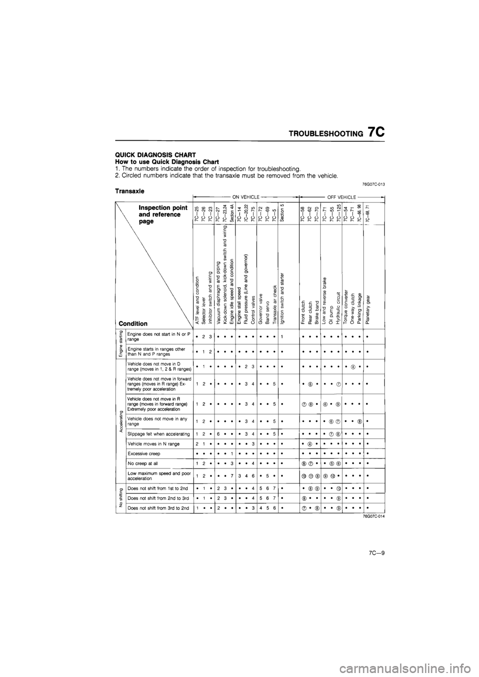
TROUBLESHOOTING
7C
QUICK DIAGNOSIS CHART
How
to use
Quick Diagnosis Chart
1.
The
numbers indicate
the
order
of
inspection
for
troubleshooting.
2. Circled numbers indicate that
the
transaxle must
be
removed from
the
vehicle.
76G07C-013
Transaxle ON VEHICLE OFF VEHICLE
•
\ Inspection point
\
and
reference
\ page
Condition
7C-25
7C-26
7C-23
10—21
7C—23,24
Section
4A
7C-14
7C—20,22
10—lb
10-12 10—69
7C—5
Section
5
7C—58
7C-62
7C-70
7C-71
7C-55
7C-125
7C-54 7C-71
7C-66,
98
7C-68,
71
\ Inspection point
\
and
reference
\ page
Condition
ATF
level
and
condition
Selector
lever
Inhibitor
switch
and
wiring
^
Vacuum
diaphragm
and
piping
|
Kick-down
solenoid,
kick-down
switch
and
wiring
Engine
idle
speed
and
condition
Engine
stall
speed
Fluid
pressure
(Line
and
governor)
Control
valves
Governor
valve
Band
servo
Transaxle
air
check
Ignition
switch
and
starter
Front
clutch
Rear
clutch
Brake
band
Low
and
reverse
brake
Oil
pump Hydraulic
circuit
Torque
converter
One-way
clutch
Parking
linkage
Planetary
gear
I
Engine
starting
Engine does
not
start
in
N or P
range •
2 3
1
Engine
starting
Engine starts
in
ranges other than
N
and P
ranges •
1 2
Accelerating
Vehicle does
not
move
in
D
range (moves
in 1, 2 & R
ranges) •
• •
•
Accelerating
Vehicle does
not
move
in
forward ranges (moves
in R
range)
Ex-
tremely poor acceleration •
• 5
• •
© •
•
• ©
•
• •
•
Accelerating
Vehicle does
not
move
in R
range (moves
in
forward range) Extremely poor acceleration 1
2 •
•
• •
•
3 4
•
• 5
• ©
© •
©
• ©
•
• •
•
Accelerating
Vehicle does
not
move
in any
range 1
2 •
•
• •
•
3 4
•
• 5
• •
• •
•
© ©
•
• ©
•
Accelerating Slippage felt when accelerating 1
2 •
6
• •
•ST
CO
•
•
• 5
• •
• •
•
© ©
•
• •
• Accelerating
Vehicle moves
in
N
range
Accelerating
Excessive creep
Accelerating
No creep
at all
©
© •
•
© ©
•
• •
•
Accelerating
Low maximum speed
and
poor acceleration 1
2 •
•
• 7
3
4 6
•
5 •
• ©
© ©
No shifting
Does
not
shift from
1
st to 2nd
•
1 •
2
3 •
•
• 4
5
6 7
• •
© ©
•
• ©
•
• •
•
No shifting
Does
not
shift from
2nd to 3rd
•
1 •
2
3 •
•
• 4
5
6 7
•
No shifting
Does
not
shift from
3rd to 2nd
1
• •
2
• •
•
• 3
4
5 6
• ©
• ©
•
• ©
•
• •
•
76G07C-014
7C-9
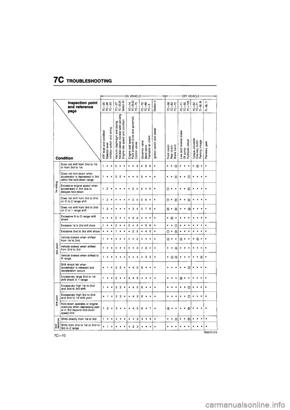
Page 1124 of 1865

7C TROUBLESHOOTING
ON VEHICLE OFF VEHICLE
-
\ Inspection point
\ and reference
\ page
Condition
LO
(O
CO CJ OJ CM I
I I
O
O
CJ
r-~
r—
7C-27
7C—23,24
Section
4A
7C—14
7C—20,22
7C-75
CO
O)
in
I
I I
o
o o
r—
r—
Section
5
CO CO
o
WON I
I I
o
o o
1— 1—
m i-
in co
S
IO
i-
1
1 1
o
o o
—
I—
7C—54
7C-71
7C-66,
98
7C—68,
71
\ Inspection point
\ and reference
\ page
Condition
A.TF
level
and
condition
Selector
lever
Inhibitor
switch
and
wiring
Vacuum
diaphragm
and
piping
Kick-down
solenoid,
kick-down
switch
and
wiring
Engine
idle
speed
and
condition
Engine
stall
speed
Fluid
pressure
(Line
and
governor)
Control
valves
Governor
valve
Band
servo
Transaxle
air
check
Ignition
switch
and
starter
Front
clutch
Rear
clutch
Brake
band
Low
and
reverse
brake
Oil pump Hydraulic
circuit
Torque
converter
One-way
clutch
Parking
linkage
Planetary
gear
No
shifting
Does
not
shift from 2nd
to
1
st or from
3rd to
1
st 1
• •
2
• •
•
• 3
4
5 6
•
No
shifting
Does
not
kick-down when accelerator
is
depressed
in 3rd
within
the
kick-down range 1
• •
3
2*
•
• 4
5
• •
• •
• ©
•
• ©
•
• •
•
No
shifting
Excessive engine speed when accelerated
in 3rd
due
to
delayed kick-down 5
• 6
• ©
• •
•
• ©
•
• •
• No
shifting
Does
not
shift from
3rd to 2nd
on
D to
2
range shift 1
2 •
5
6 •
• ©
• ®
•
• ®
•
• •
•
No
shifting
Does
not
shift from
3rd to 2nd
on
D to 1
range shift 5
7 6
• ©
• ®
•
• ®
•
• •
•
Shift
shock
Excessive
N to
D
range shift shock •
• •
2
• 1
•
3 4
•
• •
• •
© •
•
• •
•
• •
•
Shift
shock
Excessive
1
st
to
2nd shift shock 1
• •
2
• •
3
• 4
•
5 6
• •
• ©
•
• •
•
• •
•
Shift
shock
Excissive 2nd
to 3rd
shift shock •
• •
1
• •
•
2 3
•
4 5
• ©
• ©
Shift
shock
Vehicle braked when shifted from
1
st
to 2nd
Shift
shock
Vehicle braked when shifted from 2nd
to 3rd
1
• •
•
• •
•
• 3
.
2 •
•
Shift
shock
Vehicle braked when shifted
to
R range 1
• •
•
• •
•
• •
•
3 2
• •
© ©
•
• •
•
• ©
•
Shift
shock
Shift shock felt when accelerator
is
released
and
deceleration occurs •
1 •
2
3*
•
4 5
6
• •
• •
• •
•
• ©
•
• *
•
Shift
shock
Excessively large 2nd
to 1st
shift shock
in 1
range 1
• •
2
• •
3
4 5
•
• •
•
Shift
point
Excessively high
1st to 2nd
and 2nd
to
3rd shift 1
• •
2
3 •
•
4 5
6
• •
•
Shift
point
Excessively high
3rd to 2nd
and
2nd to
1
st shift point •
1 •
2
3 •
•
4 5
6
• •
• •
• •
•
• ©
•
• •
•
Shift
point
Kick-down operates
or
engine overruns when depressing
ped-
al
in 3rd
beyond kick-down speed limit
1
2 •
3
• •
•
4 5
6
• 7
•
Shift
sequence
Shifts directly from 1st
to 3rd
1
• •
•
• •
•
• 2
3
• 4
• •
• ©
•
• ©
•
• •
•
Shift
sequence
Shifts from
2nd to 1st or
2nd
to
3rd
in
2
range •
1 •
•
• •
•
2 3
•
• •
•
7C-10