Page 1461 of 1865
PARKING BRAKE 1 1
INSTALLATION OF PARKING BRAKE CABLE
1. Install in the reverse order of removal, referring to installation note for specially marked parts.
2. Tighten all nuts and bolts to the specified torque, referring to torque specifications.
3. After installation:
(1) Adjust the parking brake lever stroke. (Refer to page 11—65.)
(2) Depress the brake pedal a few times and check that the rear brakes do not drag while the wheels
are being rotated.
Torque specifications
Rear drum brake
76G11X-053
11-69
Page 1462 of 1865
1 1 PARKING BRAKE
Rear disc brake
(70—100 cm-kg, 61—87 In-lb)
86U11X-138
1. Parking brake cable (rear disc brake)
Installation Note
Parking brake cable (Rear disc brake)
Connect the cable end to the operating lever; then
tighten the locknut.
Tightening torque:
20—28 N m (2.0—2.9 m-kg, 14—21 ft-lb)
Caution
There must be no clearance between the ca-
ble end and the operating lever.
86U11X-139
11-70
Page 1465 of 1865

ANTI-LOCK BRAKE SYSTEM (ABS) 1 1
TROUBLESHOOTING
Precaution
Conditions that are not malfunctions
1. It may happen that vibration is felt in the steering wheel, body, and/or brake pedal when the ABS
is functioning; such vibration is simply an indication that the system is functioning.
2. Sound of the pump motor operating, accumulator pressure being released, or the relay operating
may be heard from the engine compartment when the engine is started as the system is being auto-
matically checked.
3. The ABS pump motor may be automatically activated even though the ABS is not operating.
4. The ABS warning light may illuminate under any of the following conditions:
• When the vehicle is traveling on snow or ice with the parking brake activated or a brake dragging
at one wheel.
• When different-sized tires are used.
• When tires of different gripping performance are used.
• When (while the vehicle is jacked up or stuck) only the front wheels are spun for 20 seconds or more.
• When there is insufficient battery voltage.
Note
Under the above conditions, the warning light will not illuminate a second time when the
ignition is switched OFF then back ON, and there will be no memory entry to the control
unit of a problem.
Troubleshooting notes
The ABS is composed of electrical components, mechanical components (hydraulic unit), and the com-
ponents of the standard brake system.
Fundamentally, malfunction of the ABS electrical or mechanical components is judged by the self-
diagnosis function within the ABS control unit. And malfunctions are indicated by the warning light
in the instrument panel.
The location
of
a malfunction is indicated by the technician switching the system to the diagnosis-indication
mode.
The self-diagnosis and indication functions must be used when malfunctions of the ABS are being
diagnosed.
76G11X-091
11—73
Page 1487 of 1865

ANTI-LOCK BRAKE SYSTEM (ABS) 1 1
86U11X-190
86U11X-191
76G11X098
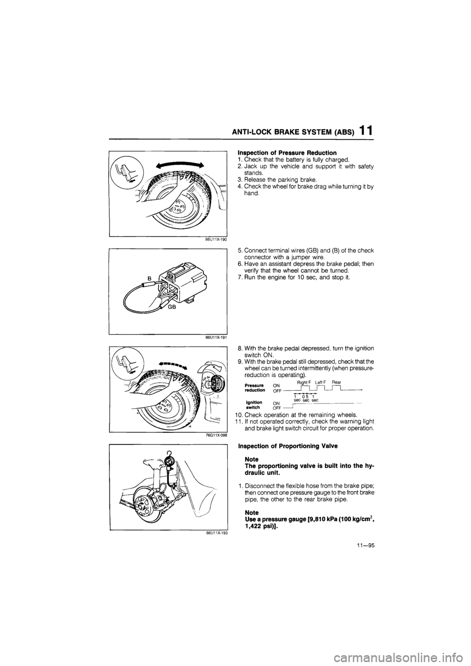
Inspection of Pressure Reduction
1. Check that the battery is fully charged.
2. Jack up the vehicle and support it with safety
stands.
3. Release the parking brake.
4. Check the wheel for brake drag while turning it by
hand.
5. Connect terminal wires (GB) and (B) of the check
connector with a jumper wire.
6. Have an assistant depress the brake pedal; then
verify that the wheel cannot be turned.
7. Run the engine for 10 sec, and stop it.
8. With the brake pedal depressed, turn the ignition
switch ON.
9. With the brake pedal still depressed, check that the
wheel can be turned intermittently (when pressure-
reduction is operating).
Right'F Left F Rear Pressure reduction
Ignition switch ON OFF
1 05 1 sec sec sec
J
10. Check operation at the remaining wheels.
11. If not operated correctly, check the warning light
and brake light switch circuit for proper operation.
Inspection of Proportioning Valve
Note
The proportioning valve is built into the hy-
draulic unit.
1. Disconnect the flexible hose from the brake pipe;
then connect one pressure gauge to the front brake
pipe, the other to the rear brake pipe.
Note
Use a pressure gauge [9,810 kPa (100 kg/cm2,
1,422 psi)].
86U11X-193
11—95
Page 1694 of 1865
WARNING AND SENDER 15
Coolant Level Warning Light
OK
Repair harness (Meter
to
coolant level sensor).
76G15X093
INSPECTION
Brake Fluid Level Sensor
1. Check for continuity of the sensor with an
ohmmeter.
Float level Continuity
Below
min
Yes
Above
min
No
2. If continuity is not as specified, replace the sensor.
86U15X-065
86U14X-066
Parking Brake Switch
1. Check for continuity between (R) terminal and a
body ground with an ohmmeter.
Lever Continuity
Pulled one notch Yes
Released No
2. If continuity is not as specified, adjust the switch
or replace the switch.
15—39
Page 1851 of 1865

TECHNICAL DATA 30
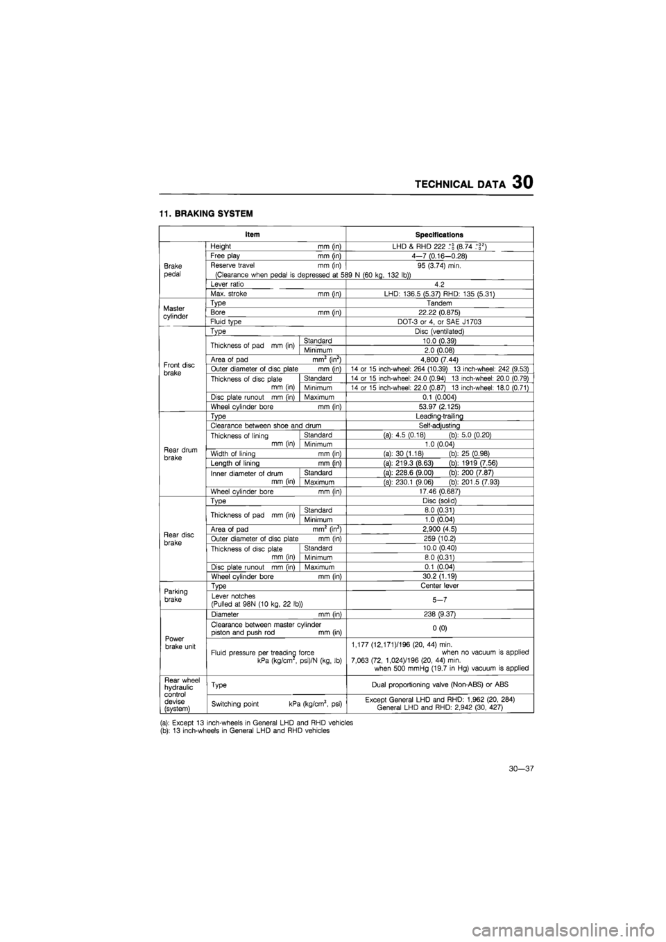
11. BRAKING SYSTEM
Item Specifications
Brake
pedal
Height
mm
(in) LHD
&
RHD 222 (8.74 _+g2)
Brake
pedal
Free play
mm
(in) 4-7 (0.16—0.28)
Brake
pedal
Reserve travel
mm (in)
(Clearance when pedal
is
depressed
at 5S
95 (3.74) min.
39
N
(60 kg, 132 lb))
Brake
pedal
Lever ratio 4.2
Brake
pedal
Max. stroke
mm (in)
LHD: 136.5 (5.37) RHD: 135 (5.31)
Master cylinder
Type Tandem Master cylinder Bore
mm
(in) 22.22 (0.875) Master cylinder Fluid type DOT-3
or 4, or
SAE J1703
Front disc brake
Type Disc (ventilated)
Front disc brake
Thickness
of
pad
mm (in)
Standard 10.0 (0.39)
Front disc brake
Thickness
of
pad
mm (in)
Minimum 2.0 (0.08)
Front disc brake
Area
of
pad mm2 (in2) 4,800 (7.44) Front disc brake Outer diameter
of
disc plate
mm (in)
14
or 15
inch-wheel: 264 (10.39)
13
inch-wheel: 242 (9.53) Front disc brake Thickness
of
disc plate
mm (in)
Standard 14
or 15
inch-wheel: 24.0 (0.94)
13
inch-wheel: 20.0 (0.79)
Front disc brake Thickness
of
disc plate
mm (in) Minimum 14
or 15
inch-wheel: 22.0 (0.87)
13
inch-wheel: 18.0 (0.71)
Front disc brake
Disc plate runout
mm (in)
Maximum 0.1 (0.004)
Front disc brake
Wheel cylinder bore
mm (in)
53.97 (2.125)
Rear drum
brake
Type Leading-trailing
Rear drum
brake
Clearance between shoe and drum Self-adjusting
Rear drum
brake
Thickness
of
lining mm (in)
Standard (a):
4.5
(0.18) (b): 5.0 (0.20)
Rear drum
brake
Thickness
of
lining mm (in) Minimum 1.0 (0.04) Rear drum
brake Width
of
lining
mm (in)
(a):
30
(1.18)
(b)
25 (0.98) Rear drum
brake Length
of
lining
mm fin)
(a): 219.3 (8.63)
(b)
1919 (7.56)
Rear drum
brake
Inner diameter
of
drum mm (in)
Standard (a): 228.6 (9.00)
(b)
200 (7.87)
Rear drum
brake
Inner diameter
of
drum mm (in) Maximum (a): 230.1 (9.06)
(b)
201.5 (7.93)
Rear drum
brake
Wheel cylinder bore
mm (in)
17.46 (0.687)
Rear disc
brake
TvDe Disc (solid)
Rear disc
brake
Thickness
of
pad
mm (in)
Standard 8.0 (0.31)
Rear disc
brake
Thickness
of
pad
mm (in)
Minimum 1.0 (0.04)
Rear disc
brake
Area
of
pad mm2 (in2) 2,900 (4.5) Rear disc
brake Outer diameter
of
disc plate
mm (in)
259 (10.2) Rear disc
brake Thickness
of
disc plate mm (in)
Standard 10.0 (0.40)
Rear disc
brake Thickness
of
disc plate mm (in) Minimum 8.0 (0.31)
Rear disc
brake
Disc
Dlate runout mm fin)
Maximum 0.1 (0.04)
Rear disc
brake
Wheel cylinder bore
mm (in)
30.2 (1.19)
Parking
brake
TvDe Center lever Parking
brake Lever notches
(Pulled
at
98N
(10
kg,
22 lb))
5-7
Power
brake unit
Diameter
mm (in)
238 (9.37)
Power
brake unit
Clearance between master cylinder piston and push
rod mm
(in) 0(0)
Power
brake unit Fluid pressure per treading force
kPa (kg/cm
,
psi)/N (kg,
lb)
1,177 (12,171 )/196 (20,
44)
min. when
no
vacuum
is
applied 7,063 (72, 1,024)/196 (20,
44)
min.
when 500 mmHg (19.7
in
Hg) vacuum
is
applied
Rear wheel hydraulic control devise (svstem)
Type Dual proportioning valve (Non-ABS)
or
ABS Rear wheel hydraulic control devise (svstem) Switching point kPa (kg/cm2,
psi)
Except General LHD and RHD: 1,962 (20, 284) General LHD and RHD: 2,942 (30, 427)
(a): Except
13
inch-wheels
in
General LHD and RHD vehicles (b):
13
inch-wheels
in
General LHD and RHD vehicles
30—37