Page 7 of 1865
FUNDAMENTAL PROCEDURES G
Depending on where they are;
1. Sealant should be applied to gaskets
2. Oil should be applied to the moving components
of parts
3. Specified oil or grease should be applied at the
prescribed locations (oil seals, etc.) before as-
sembly.
47U0GX-012
ADJUSTMENTS
Use suitable gauges and/or testers when making var-
ious adjustments.
67U0GX-002
ELECTRICAL SYSTEM
Be sure to disconnect the battery cable from the nega-
tive (-) terminal of the battery.
Never pull on the wiring when disconnecting con-
nectors.
When locking connectors, make sure to listen for a
click that will let you know they are securely locked.
Handle sensors and relays carefully. Be careful not
to drop them or strike them against other parts.
47U0GX-014
RUBBER PARTS AND TUBING
Always prevent gasoline or oil from getting on rub-
ber parts or tubing.
47U0GX-015
G—5
Page 49 of 1865

ON-VEHICLE MAINTENANCE (TIMING BELT) 1 A
76G01A-027
76G01B-024
76G01A-028
/Jf
ry.
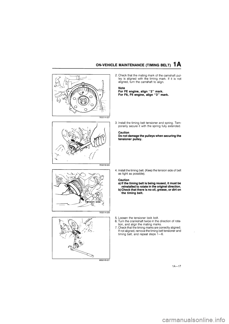
2. Check that the mating mark of the camshaft pul-
ley is aligned with the timing mark. If it is not
aligned, turn the camshaft to align.
Note
For FE engine, align "2" mark.
For F8, F6 engine, align "3" mark.
3. Install the timing belt tensioner and spring. Tem-
porarily secure it with the spring fully extended.
Caution
Do not damage the pulleys when securing the
tensioner pulley.
4. Install the timing belt. (Keep the tension side of belt
as tight as possible).
Caution
a) If the timing belt is being reused, it must be
reinstalled to rotate in the original direction.
b) Check that there is no oil, grease, or dirt on
the timing belt.
5. Loosen the tensioner lock bolt.
6. Turn the crankshaft twice in the direction of rota-
tion, and align the mating marks.
7. Check that the timing marks are correctly aligned.
If not aligned, remove the timing belt tensioner and
timing belt, and repeat steps 1—6.
69G01B-027
1A-17
Page 54 of 1865
1 A ON-VEHICLE MAINTENANCE (CYLINDER HEAD)
69G01B-037
76G01A-111
4. Remove the timing belt and secure it out of the way
to prevent damage during removal and installation
of the cylinder head.
Cylinder head bolt
Loosen the cylinder head bolts in two or three steps
in the order shown in the figure.
Disassembly of Cylinder Head
Refer to page 1A—40.
Inspection of Cylinder Head
Refer to page 1A—48.
Assembly of Cylinder Head
Refer to page 1A—73.
76G01A-033
1A—22
Page 67 of 1865

REMOVAL 1A
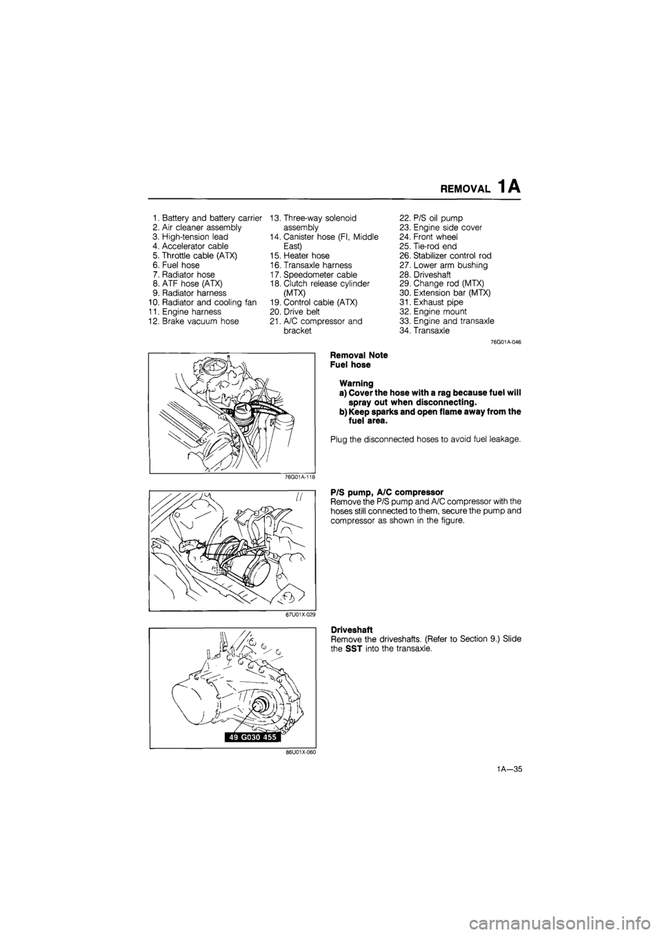
1. Battery and battery carrier 13. Three-way solenoid 22. P/S oil pump
2. Air cleaner assembly assembly 23. Engine side cover
3. High-tension lead 14. Canister hose (Fl, Middle 24. Front wheel
4. Accelerator cable East) 25. Tie-rod end
5. Throttle cable (ATX) 15. Heater hose 26. Stabilizer control rod
6. Fuel hose 16. Transaxle harness 27. Lower arm bushing
7. Radiator hose 17. Speedometer cable 28. Driveshaft
8. ATF hose (ATX) 18. Clutch release cylinder 29. Change rod (MTX)
9. Radiator harness (MTX) 30. Extension bar (MTX)
10. Radiator and cooling fan 19. Control cable (ATX) 31. Exhaust pipe
11. Engine harness 20. Drive belt 32. Engine mount
12. Brake vacuum hose 21. A/C compressor and 33. Engine and transaxle
bracket 34. Transaxle
76G01A-046
Removal Note
Fuel hose
Warning
a) Cover the hose with a rag because fuel will
spray out when disconnecting.
b) Keep sparks and open flame away from the
fuel area.
Plug the disconnected hoses to avoid fuel leakage.
76G01A-11E
P/S pump, A/C compressor
Remove the P/S pump and A/C compressor with the
hoses still connected to them, secure the pump and
compressor as shown in the figure.
67U01X-029
Driveshaft
Remove the driveshafts. (Refer to Section 9.) Slide
the SST into the transaxle.
86U01X-060
1A—35
Page 116 of 1865
1A ASSEMBLY (TIMING BELT)
Tensioner lock bolt
69G01B-165
76G01A-085
79G01C-097
Timing Belt Idler Pulley
Install the timing belt idler pulley.
Tightening torque:
37—52 Nm (3.8—5.3 m-kg, 27—38 ft-lb)
Timing Belt Tensioner
1. Install the timing belt tensioner and tensioner
spring.
2. Tentatively secure the tensioner with the spring fully
extended.
Timing Belt
1. Install the timing belt, (keep the tension side of belt
as tight as possible.)
Caution
a) If the timing belt is being reused, it must be
reinstalled to rotate in the original direction.
b) Check that there is no oil, grease, or dirt on
the timing belt.
2. Loosen the tensioner lock bolt.
3. Turn the crankshaft twice in the direction of rotation.
4. Check that the mating marks are correctly aligned.
If not aligned, remove the timing belt and tension-
er, and repeat the above-mentioned procedure.
5. Tighten the timing belt tensioner lock bolt.
Tightening torque:
37—52 Nm (3.8—5.3 m-kg, 27—38 ft-lb)
4BGQ1A-186
1A—84
Page 124 of 1865
1A INSTALLATION
ENGINE INSTALLATION
Install the engine and transaxle assembly.
Warning: Be sure the vehicle is securely supported.
Torque Specifications
16—27 N-m (1.6—2.8 m-kg, 12—20 ft-lb)
.OT-
9
85—117 N-m (6.7-11.9 m-kg, 63—86 ft-lb)
8—11 N-m (80—110 cm-kg, 69—95 In-lb)
44—64 N-m I (4.5—6.5 m-kg,
_
33-47 ft-lb)
16—27 N-m (1.6—2.8 m-kg, 12—20 ft-lb)
/ 64—89 N-m (6.5—9.1 m-kg, 47—66 ft-lb)
37—52 N-m (3.8—5.3 m-kg, 27—38 ft-lb)
31—46 N-m (3.2-4.7 m-i 23—34 ft-lb)
39—59 N-m _ (4.0—6.0 m-kg, 29—43 ft-lb)
19—25 N-m (1.9—2.6 m-kg, 14—1S ft-lb)
36-54 N-m (3.7—5.5 m-kg, 27—40 ft-lb)
16—23 N-m (1.6—2.3 m-kg, 12—17 ft-lb)
5—7 N-m (50—70 cm-kg, 43—61 In-lb)
-31—46 N-m (3.2—4.7 m-kg, 23—34 ft-lb)
9—13 N m (90—130 cm-kg, 78—113 ft-lb)
29—44 N-m (3.0—4.5 m-kg, 22—33 ft-lb)
8-11 N-m (80—110 cm-kg, 69—95
31—46 N-m (3.2—4.7 m-kg.
8—11 N-m (80
16—23
88—118 N-m (9.0—12.0 m-kg, 65—87 ft-lb)
43—54 N-m (4.4—5.5 m-kg, 32—40 ft-lb)
8—11 N-m (80—110 cm-kg, 69—95 In-lb)
86U01X-180
1A—92
Page 126 of 1865
1A INSTALLATION
Driveshaft
1. Apply grease to the end of the driveshaft.
2. Install the driveshaft and a new clip.
Caution
a) When installing the driveshaft, be careful
not to damage the oil seal.
b) After installation, pull the front hub outward
to confirm that the driveshaft is securely
held by the clip.
86U01X-184
Lower Arm
Install the lower arm ball-joint to the knuckle; then tight-
en the lock nut.
Tightening torque:
43—54 N-m (4.4—5.5 m-kg, 32—40 ft-lb)
86U01X-185
Tie-Rod End
1. Install the tie-rod end to the knuckle.
Tightening torque:
29—44 N-m (3.0—4.5 m-kg, 22—33 ft-lb)
2. Install the cotter pin.
86U01X-186
Stabilizer Control Rod
Install and adjust the front stabilizer control rods.
Dimension A: 20.1 mm (0.79 in)
Tightening torque: 16—23 N-m (1.6—2.3 m-kg, 12—17 ft-lb)
Install the front wheel.
Tightening torque:
88—118
N
m (9.0—12.0 m-kg, 65—87 ft-lb)
1A—94
Page 145 of 1865

1 B ON-VEHICLE MAINTENANCE (TIMING BELT)
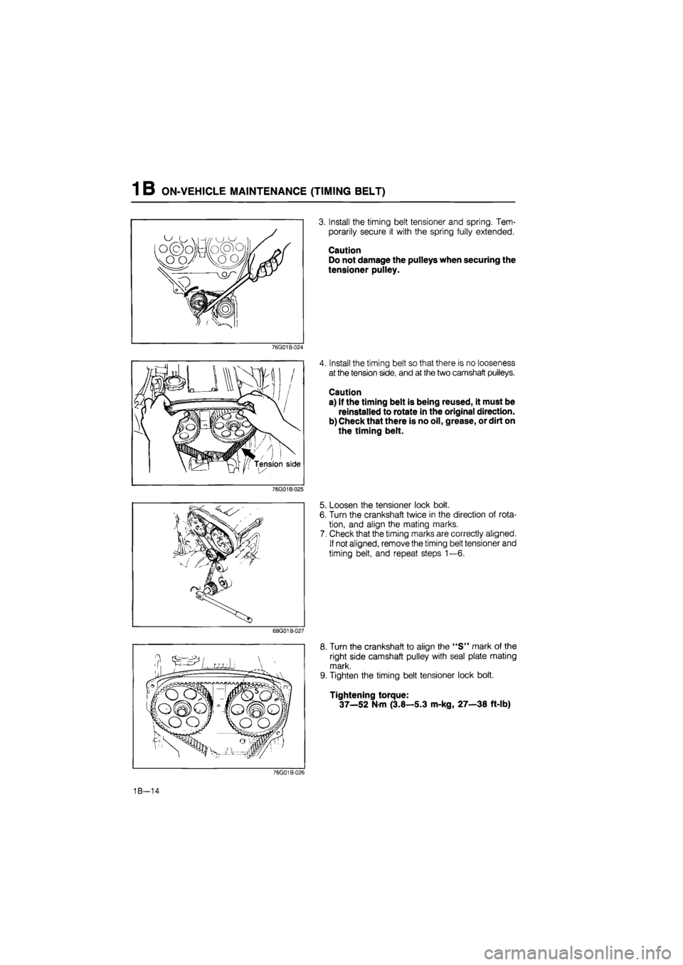
3. Install the timing belt tensioner and spring. Tem-
porarily secure it with the spring fully extended.
Caution
Do not damage the pulleys when securing the
tensioner pulley.
76G01B-024
4. Install the timing belt so that there is no looseness
at the tension side, and at the two camshaft pulleys.
Caution
a) If the timing belt is being reused, it must be
reinstalled to rotate in the original direction.
b) Check that there is no oil, grease, or dirt on
the timing belt.
76G01B-025
5. Loosen the tensioner lock bolt.
6. Turn the crankshaft twice in the direction of rota-
tion, and align the mating marks.
7. Check that the timing marks are correctly aligned.
If not aligned, remove the timing belt tensioner and
timing belt, and repeat steps 1—6.
69G01B-027
8. Turn the crankshaft to align the "S" mark of the
right side camshaft pulley with seal plate mating
mark.
Tighten the timing belt tensioner lock bolt.
Tightening torque:
37—52 Nm (3.8—5.3 m-kg, 27—38 ft-lb)
76G01B-026
1B—14