Page 978 of 1865
7B INSPECTION AND REPAIR
86U07B-186
86U07B-187
11. Install the oil pump cover to the oil pump body.
Tighten the bolts in sequence.
Tightening torque:
8—11 Nm (82—112 cm-kg, 71—97 in-lb)
12. Install the oil pump shaft and check for smooth oil
pump operation.
13. Install the seal rings.
14. Apply petroleum jelly to the bearing race
to
secure
it to the oil pump cover; then install it on the oil
pump cover.
Bearing race outer diameter:
88.0 mm (3.46 in)
86U07B-188
7B—112
Page 999 of 1865
INSPECTION AND REPAIR 7B
2. Install the spring to the piston.
3. Install the stopper plug.
(1) Apply ATF to O-ring, and install it onto the stop-
per plug.
(2) Install the stopper plug.
86U07B-258
4. Install the snap ring while holding in the stopper
plug.
86U07B-259
GOVERNOR ASSEMBLY (G4A-HL)
Disassembly
Disassemble in the sequence shown in the figure
referring to the disassembly note for the specially
marked part.
1. Roll pin
2. Governor driven gear
3. Governor valve
4. Governor carrier and sleeve
76G07B-139
Disassembly note
Roll pin
1. Secure the governor assembly in a vise.
Note
Use the protective plates to prevent damage
to the governor assembly.
2. Remove the roll pin from the governor assembly.
83U07B-266
7B-133
Page 1048 of 1865
7B INSPECTION AND REPAIR
IDLE GEAR
Disassembly
Disassemble in the sequence shown in the figure referring to the disassembly note for the specially
marked parts.
1. Locknut
2. Idle gear
bearing
3. Spacer
4. Idle gear
5. Adjust shim
6. Idle gear
bearing
7. Idle shaft
8. Bearing outer
race
9. Bearing outer
race
86U07B-337
Disassembly note
Locknut
Secure the idle shaft in a vise with the SST; then re-
move the locknut.
Note
Use the protective plates to prevent damage
to the SST.
86U07B-338
Bearing outer race
Remove the bearing outer race from the idle gear with
the SST.
86U07B-339
7B—182
Page 1049 of 1865
INSPECTION AND REPAIR 7B
Inspection
Check the following and replace any faulty parts.
1. Damaged or worn idle gear
2. Damaged or worn bearing
86U07B-340
Assembly
1. Press the bearing outer races in with the SST.
86U07B-341
86U07B-342
2. Install the idle gear bearing onto the idle shaft, then
install the idle gear, adjust shim, spacer, and
bearing.
3. Secure the idle shaft in a vise with the SST; then
tighten the locknut to the lower limit of the tighten-
ing torque.
Tightening torque:
128 N-m (13 m-kg, 94 ft-lb)
Note
Use the protective plates to prevent damage
to the SST.
86U07B-343
7B—183
Page 1050 of 1865

7B INSPECTION AND REPAIR
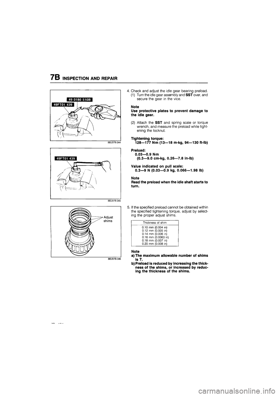
4. Check and adjust the idle gear bearing preload.
(1) Turn the idle gear assembly and SST over, and
secure the gear in the vice.
Note
Use protective plates to prevent damage to
the idle gear.
(2) Attach the SST and spring scale or torque
wrench, and measure the preload while tight-
ening the locknut.
Tightening torque:
128—177
N m
(13—18 m-kg, 94—130 ft-lb)
49FT01 439
Preload:
0.03—0.9 N-m
(0.3—9.0 cm-kg, 0.26—7.8 in-lb)
Value indicated on pull scale:
0.3—9 N (0.03—0.9 kg, 0.066—1.98 lb)
Note
Read the preload when the idle shaft starts to
turn.
86U07B-345
86U07B-346
5. If the specified preload cannot be obtained within
the specified tightening torque, adjust by select-
ing the proper adjust shims.
Thickness
of
shim
0.10 mm (0.004
in)
0.12
mm
(0.005
in)
0.14
mm
(0.006
in)
0.16
mm
(0.0063
in)
0.18 mm (0.007
in)
0.20 mm (0.008
in)
Note
a) The maximum allowable number of shims
is 7.
b) Preload is reduced by increasing the thick-
ness of the shims, or increased by reduc-
ing the thickness of the shims.
Page 1138 of 1865
7C ELECTRIC COMPONENTS
Adjustment
1. Loosen the kick-down switch locknuts.
2. Depress the accelerator pedal fully.
3. Turn the switch until the threaded case touches the
stop.
4. Turn the switch counterclockwise one-half turn.
5. Secure the switch with the locknut.
76G07C-039
KICK-DOWN SOLENOID
Check that the rod extends when 12 V is applied.
76G07C-040
7C-24
Page 1156 of 1865
7C DISASSEMBLY
Procedure
1. Remove the anchor-end bolt and locknut.
76G07C-088
2. Remove the brake band and strut.
Note
Use a piece of wire to secure the brake band
so that it is not damaged by being stretched.
76G07C-089
3. Remove the front clutch.
76G07C-090
4. Remove the rear clutch.
76G07C-091
7C-42
Page 1181 of 1865
INSPECTION AND REPAIR 7C
76G07C-171
76G07C-172
76G07C-173
Disassembly note
Parking gear
Remove the parking gear from the drive hub by first
removing the parking gear spring by pushing in the
two pins which project from the internal gear.
Inspection
Check the following and replace any faulty parts.
1. Broken or worn snap ring
2. Damaged or worn gear
Assembly
1. Install the drive hub to the internal gear; then in-
stall the snap ring.
2. Install the parking gear onto the drive hub with the
step facing upward.
3. Apply petroleum jelly to the pins to secure them;
then install them into the drive hub.
76G07C-174
7C-67