Page 1186 of 1865

7C INSPECTION AND REPAIR
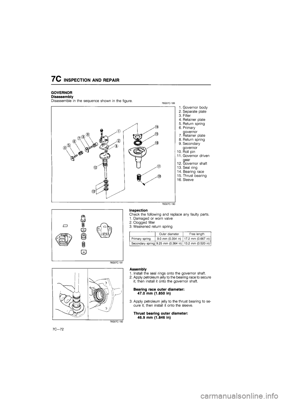
GOVERNOR
Disassembly
Disassemble in the sequence shown in the figure. 76G07C-1E
1. Governor body
2. Separate plate
3. Filter
4. Retainer plate
5. Return spring
6. Primary
governor
7. Retainer plate
8. Return spring
9. Secondary
governor
10. Roll pin
11. Governor driven
gear
12. Governor shaft
13. Seal ring
14. Bearing race
15. Thrust bearing
16. Sleeve
76G07C-190
Inspection
Check the following and replace any faulty parts.
1. Damaged or worn valve
2. Clogged filter
3. Weakened return spring
Outer diameter Free length
Primary spring 9.0 mm (0.354 in) 17.2 mm (0.667 in)
Secondary spring 9.25 mm (0.364 in) 13.2 mm (0.520 in)
76G07C-191
76G07C-192
7C-72
Assembly
1. Install the seal rings onto the governor shaft.
2. Apply petroleum jelly to the bearing race to secure
it; then install it onto the governor shaft.
Bearing race outer diameter:
47.0 mm (1.850 in)
3. Apply petroleum jelly to the thrust bearing to se-
cure it; then install it onto the sleeve.
Thrust bearing outer diameter:
46.9 mm (1.846 in)
Page 1187 of 1865
INSPECTION AND REPAIR 7C
4. Install the governor shaft into the sleeve.
76G07C-193
76G07C-194
76G07C-195
5. Secure the governor in a vise; then install the gover-
nor driven gear with the roll pin.
Note
Use protective plates in the vice to prevent
damage to the governor.
6. Install the secondary governor valve and return
spring; then install the retainer plate.
Note
Install the retainer plate with the spring fit over
the pin.
7. Install the primary governor and return spring; then
install the retainer plate.
Note
Install the retainer plate with the spring fit over
the pin.
76G07C-196
7C-73
Page 1188 of 1865
7C INSPECTION AND REPAIR
8. Install the filter into the separate plate.
76G07C-198
10. Secure the governor in the vise; tighten the gover-
nor body mounting bolts to the specified torque.
Tightening torque:
8—11 N
m
(80—110 cm-kg, 69—95 in-lb)
Note
Use protective plates in the vice to prevent
damage to the governor.
76G07C-199
11. Check that when compressed air is blown through
port A, the valve functions (rattles).
Air Pressure:
491 kPa (5.0 kg/cm2, 71 psi) max.
Caution
Apply air for no more than 5 seconds.
76G07C-200
7C—74
Page 1198 of 1865
7C INSPECTION AND REPAIR
Disassembly note
Locknut
Secure the idle shaft in a vise with the SST; then re-
move the locknut.
Note
Use the protective plates in the vice to pre-
vent damage to the SST.
76G07C-217
Bearing outer race
Remove the bearing outer race from the idle gear with
the SST.
49 FT01 361
86U07B-339
Inspection
Check the following and replace any faulty parts.
1. Damaged or worn idle gear
2. Damaged or worn bearing
86U07B-340
Assembly
1. Press the bearing outer races in with the SST.
86U07B-341
7C-84
Page 1199 of 1865

INSPECTION AND REPAIR 7C
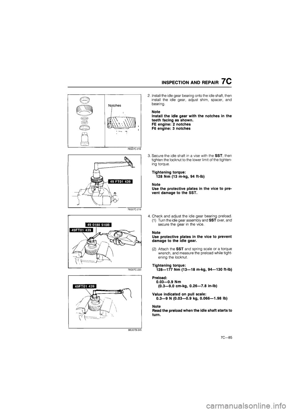
n Notches
m
«
m
«
i * •"-=- —*
76G07C-218
49FT01 439
86U07B-345
Install the idle gear bearing onto the idle shaft, then
install the idle gear, adjust shim, spacer, and
bearing.
Note
Install the idle gear with the notches in the
teeth facing as shown.
FE engine: 2 notches
F6 engine: 3 notches
Secure the idle shaft in a vise with the SST; then
tighten the locknut to the lower limit of the tighten-
ing torque.
Tightening torque:
128 N-m (13 m-kg, 94 ft-lb)
Note
Use the protective plates in the vice to pre-
vent damage to the SST.
Check and adjust the idle gear bearing preload.
(1) Turn the idle gear assembly and SST over, and
secure the gear in the vice.
Note
Use protective plates in the vice to prevent
damage to the idle gear.
(2) Attach the SST and spring scale or a torque
wrench, and measure the preload while tight-
ening the locknut.
Tightening torque:
128—177 N-m (13—18 m-kg, 94—130 ft-lb)
Preload:
0.03—0.9 Nm
(0.3—9.0 cm-kg, 0.26—7.8 in-lb)
Value indicated on pull scale:
0.3—9 N (0.03—0.9 kg, 0.066—1.98 lb)
Note
Read the preload when the idle shaft starts to
turn.
7C—85
Page 1218 of 1865
7C ASSEMBLY
76G07C-270
76G07C-271
10. Check the low and reverse brake clearance.
(1) Measure the clearance between the one-way
clutch and the low and reverse brake retain-
ing plate.
(2) If the clearance is not within specification, ad-
just it by selecting a proper retaining plate.
Low and reverse brake clearance:
0.8—1.05 mm (0.032—0.041 in)
Retaining plate sizes mm (in)
4.6 (0.181) 4.8 (0.189) 5.0 (0.197)
5.2 (0.205) 5.4 (0.213) 5.6 (0.220)
11. Blow compressed air into the fluid hole of the trans-
axle case to check the operation of the low and
reverse brake.
12. Install the one-way clutch inner race assembly.
76G07C-272
13. Apply petroleum jelly to the bearing race to secure
it; then install it onto the one-way clutch inner race
assembly.
Bearing race outer diameter:
70.0 mm (2.76 in)
14. Apply petroleum jelly to the thrust bearing to se-
cure it; then install it into the drum hub assembly.
Thrust bearing outer diameter:
69.9 mm (2.75 in)
76G07C-273
7C-104
Page 1219 of 1865
ASSEMBLY 7C
15. Install the drum hub assembly.
76G07C-274
76G07C-275
16. Apply petroleum jelly to the thrust bearing to se-
cure it; then install it into the drum hub assembly.
Thrust bearing outer diameter:
52.9 mm (2.08 in)
17. Apply petroleum jelly to the bearing race to secure
it; then install it into the transaxle case.
Bearing race outer diameter:
51.5 mm (2.03 in)
18. Install the parking pawl assembly.
19. Move the manual shaft and check that the park-
ing pawl meshes properly with the parking gear
when the manual shaft is at P.
76G07C-276
20. Install the governor inlet and outlet pipe.
76G07C-277
7C—105
Page 1222 of 1865
7C ASSEMBLY
76G07C-283
76G07C-284
5. Install the servo into the transaxle case.
(1) Install the return spring and servo retainer.
(2) Compress the servo retainer with the SST.
(3) Install the snap ring.
(4) Remove the SST.
6. Install the spacer onto the sun gear.
7. Install the sun gear into the connecting shell.
8. Apply petroleum jelly to the bearing race to secure
it; then install it onto the connecting shell.
Bearing race outer diameter:
70.0 mm (2.76 in)
9. Apply petroleum jelly to the thrust bearing to se-
cure it; then install it onto the one-way clutch inner
race.
Thrust bearing outer diameter:
69.9 mm (2.75 in)
76G07C-285 10. Install the sun gear and connecting shell into the
drum hub assembly.
11. Apply petroleum jelly to the thrust bearing to se-
cure it; then install it into the front planetary carrier.
Thrust bearing outer diameter:
46.9 mm (1.85 in)
12. Install the seal sleeve.
76G07C-286
7C—108