Page 1530 of 1865
REAR SHOCK ABSORBER AND SPRING 1 3
86U13X062
86U13X-063
86U13X-064
Inspection Note
Check the following and repair or replace any faulty
parts.
1. Oil leakage or noise from shock absorbers
2. Deterioration or damage of mounting block
3. Wear or damage of bound stopper
4. Rotation of the control rod (AAS).
Assembly Note
1. Set the SST in a vise
2. Secure the shock absorber in the SST.
3. Install the bound stopper and dust boot onto the
shock absorber.
4. Install the compressed coil spring (compressed
with SST).
5. Install the spring seat and mounting block.
6. Remove the SST.
7. Secure the mounting blocks in the vise.
Caution
Use copper or aluminum plate in the jaws of
a vice.
8. Tighten the piston rod upper nut.
Tightening torque:
64—84 N-m (6.5—8.2 m-kg, 47—59 ft-lb)
Caution
Check that the spring is well seated in the up-
per seats.
76G13X-023
13—33
Page 1595 of 1865
1 4 DOOR MIRROR
DOOR MIRROR
DISASSEMBLY l ,
1 Warm the frame and the mirror glass with a lamp
(500W) to approx. 70°C (158°F) for approx. 3
minutes.
2. Insert a scraper between the mirror glass and the
frame, then pry the mirror loose.
3. Remove any remaining adhesive.
ASSEMBLY
1. Warm the frame with a lamp.
2. Install the glass in the frame, then gently press it
in to secure it.
86U14X-107
14—44
Page 1600 of 1865

WINDSHIELD GLASS 1 4
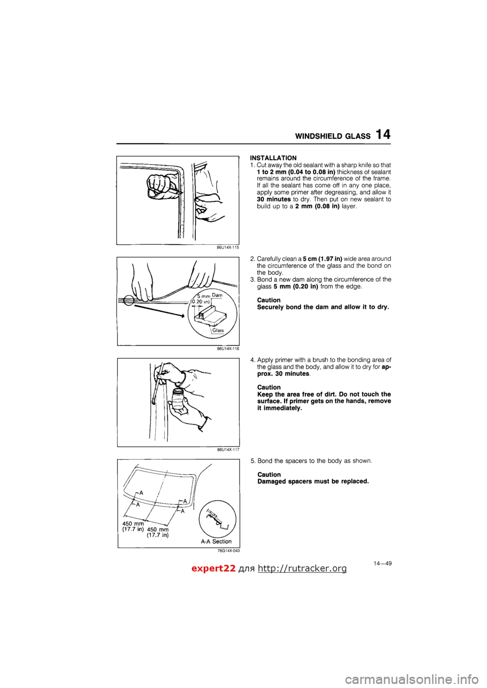
INSTALLATION
1. Cut away the old sealant with a sharp knife so that
1 to 2 mm (0.04 to 0.08 in) thickness of sealant
remains around the circumference of the frame.
If all the sealant has come off in any one place,
apply some primer after degreasing, and allow it
30 minutes to dry. Then put on new sealant to
build up to a 2 mm (0.08 in) layer
86U14X-115
2. Carefully clean a 5 cm (1.97 in) wide area around
the circumference of the glass and the bond on
the body.
3. Bond a new dam along the circumference of the
glass 5 mm (0.20 in) from the edge.
Caution
Securely bond the dam and allow it to dry.
86U14X-116
4. Apply primer with a brush to the bonding area of
the glass and the body, and allow it to dry for ap-
prox. 30 minutes.
Caution
Keep the area free of dirt. Do not touch the
surface. If primer gets on the hands, remove
it immediately.
86U14X-117
5. Bond the spacers to the body as shown.
Caution
Damaged spacers must be replaced.
76G14X-043
expert22 f
n http://rutracker.org
Page 1607 of 1865

14 REAR WINDOW GLASS
2. Carefully clean and remove any grease from a 5
cm (1.97 in) wide area around the circumference
of the glass and the remaining bond on the body.
3. Bond a dam along the circumference of the glass
8 mm (0.31 in) from the edge.
Caution
Securely bond the dam and let it dry.
63U14X-064
4. Apply primer with a brush to the circumference of
the glass and the body and
it
them to naturally dry
for 20 to 30 minutes.
Caution
Be sure not to allow dirt, water, oil, etc. to
come in contact with the coated surfaces and
do not touch it with your hand.
63U14X-065
5. Install the spacers at the positions shown in the
figure.
Caution
Spacer, with flaws, must be replaced.
63U14X066
6. When the primer has dried, apply an 11 mm (0.43
in) thick bead of repair seal (B001 77 739) 11 mm
(0.43 in) from the periphery of the window glass
using a sealant gun.
Caution
Cut the nozzle of the repair seal cartridge as
illustrated in the figure.
If necessary, smooth the repair seal to correct
any irregularities.
63U14X-067
14-56
Page 1611 of 1865

1 4 REAR HATCH GLASS
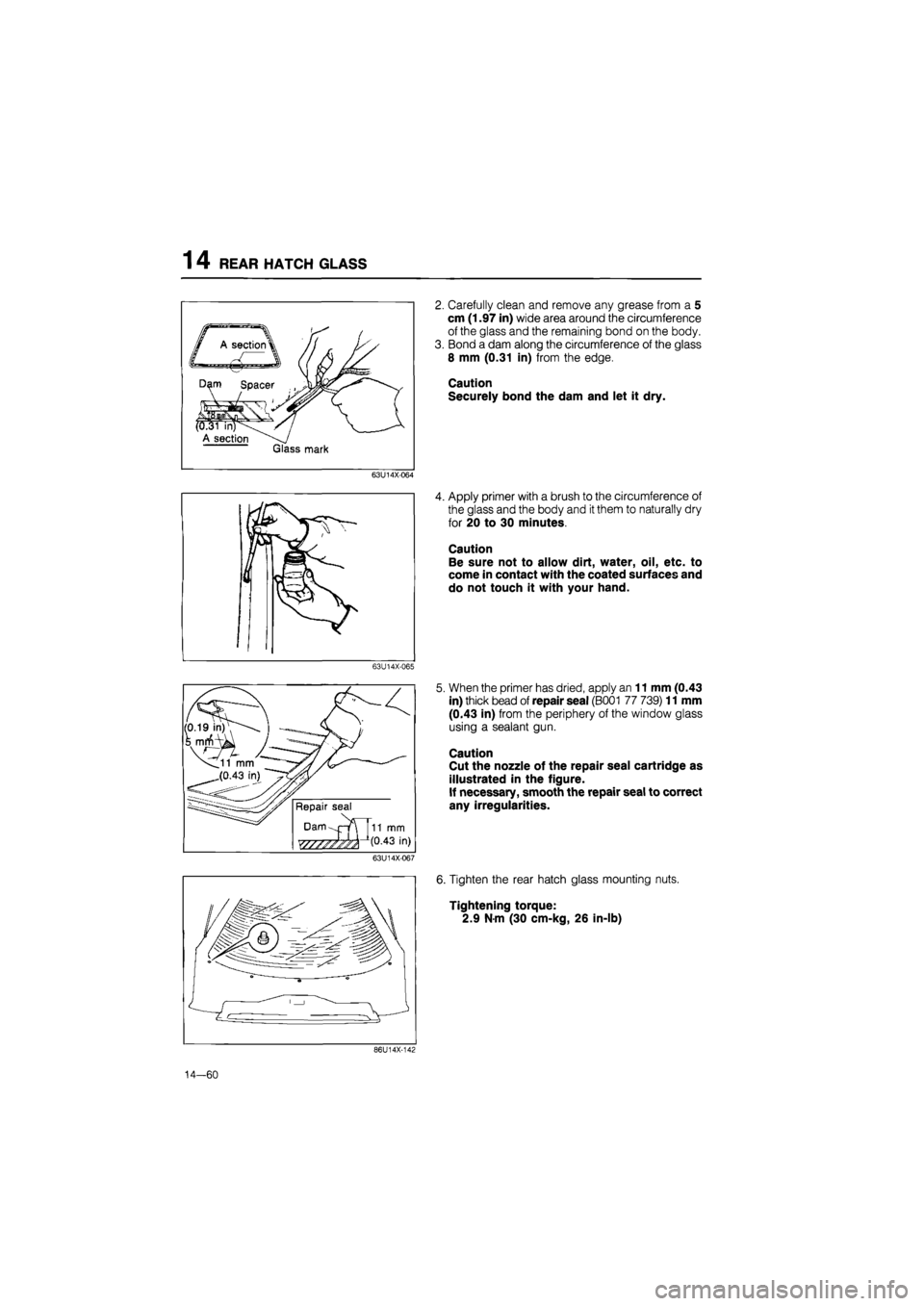
2. Carefully clean and remove any grease from a 5
cm (1.97 in) wide area around the circumference
of the glass and the remaining bond on the body.
3. Bond a dam along the circumference of the glass
8 mm (0.31 in) from the edge.
Caution
Securely bond the dam and let it dry.
63U14X-064
4. Apply primer with a brush to the circumference of
the glass and the body and
it
them to naturally dry
for 20 to 30 minutes.
Caution
Be sure not to allow dirt, water, oil, etc. to
come in contact with the coated surfaces and
do not touch it with your hand.
63U14X-065
5. When the primer has dried, apply an 11 mm (0.43
in) thick bead of repair seal (B001 77 739) 11 mm
(0.43 in) from the periphery of the window glass
using a sealant gun.
Caution
Cut the nozzle of the repair seal cartridge as
illustrated in the figure.
If necessary, smooth the repair seal to correct
any irregularities.
63U14X-067
6. Tighten the rear hatch glass mounting nuts.
Tightening torque:
2.9 N-m (30 cm-kg, 26 in-lb)
86U14X-142
14—60
Page 1631 of 1865

14 INSTRUMENT PANEL
INSTALLATION
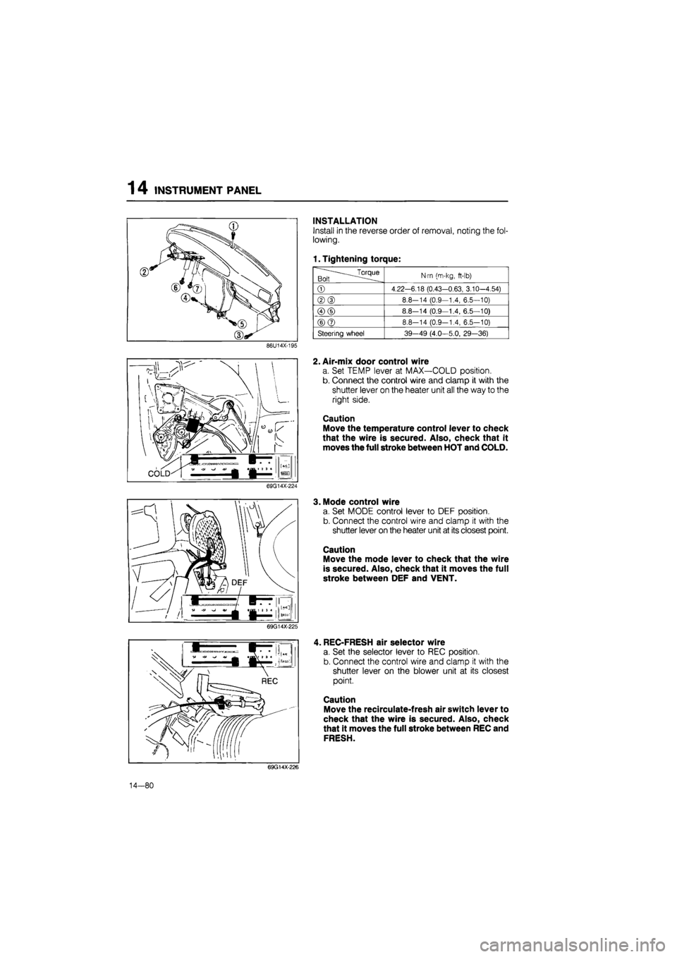
Install in the reverse order of removal, noting the fol-
lowing.
1. Tightening torque:
.^Torque Bolt
N-m (m-kg,
ft-lb)
©
4.22-6.18 (0.43-0.63, 3.10-4.54)
®(D
8.8-14 (0.9—1.4, 6.5—10)
©(D
8.8—14 (0.9—1.4, 6.5—10)
©@
8.8-14 (0.9-1.4, 6.5-10)
Steering wheel 39-49 (4.0—5.0, 29—36)
86U14X-195
2. Air-mix door control wire
a. Set TEMP lever at MAX—COLD position.
b. Connect the control wire and clamp it with the
shutter lever on the heater unit all the way to the
right side.
Caution
Move the temperature control lever to check
that the wire is secured. Also, check that it
moves the full stroke between HOT and COLD.
69G14X-224
3. Mode control wire
a. Set MODE control lever to DEF position.
b. Connect the control wire and clamp it with the
shutter lever on the heater unit at its closest point.
Caution
Move the mode lever to check that the wire
is secured. Also, check that it moves the full
stroke between DEF and VENT.
69G14X-225
, REC-FRESH air selector wire
a. Set the selector lever to REC position.
b. Connect the control wire and clamp it with the
shutter lever on the blower unit at its closest
point.
Caution
Move the recirculate-fresh air switch lever to
check that the wire is secured. Also, check
that it moves the full stroke between REC and
FRESH.
69G14X-226
14—80
Page 1638 of 1865
SLIDING SUNROOF 14
76U14X-063
76U14X-064
76U14X-065
8. Install the lower panel and tighten the screws.
9. Install the guide front and tighten the screws.
10. Pull out the drip rail from the rear, and secure the
link by the screw.
11. Using the handle turn the motor to fully open the
lower panel.
Note
a) Because the roof panel and lower panel
might interfere with each other when the
lower panel is opened, check as shown in
the figure, that the guide roller is completely
fitted into the guide rail.
b)Turn the motor while pushing the cable.
12. Secure the deflector by tightening the screw, and
then install the deflector link.
13. Turn the motor using the handle, and visually check
the sliding, tilt-down and tilt-up operations.
76U14X066
14—87
Page 1639 of 1865
1 4 SLIDING SUNROOF
76U14X-067
Set plate
76U14X-068
1.5mm (0.016 in)
: ? ©—
A-A Cross section
76U14X-069
B-B Cross section
Adjust screw Fitting screw jj
Fitting screw®
14. Fully close the lower panel.
15. Install the slide panel to the lower panel, and tight-
en securely.
16. Insert the sun shade from the notch in the set plate,
and push it all the way back.
17. Insert the set plate cap.
18. Adjust the height of the slide panel.
(Cross-section A-A)
Adjust so that the height difference between the
outer panel and roof panel is 1.5 mm (0.06 in)
max.
(Cross-section B-B adjustment)
(1) Loosen installation screws (1) and (2).
If the adjustment is only about 2 mm (0.08 in)
don't loosen screw (1).
(2) Turn the screws to adjust.
Turning to the right raises, and to the left lowers.
(3) Tighten installation screws (1) and (2).
76U14X-070
14-88