Page 1223 of 1865
ASSEMBLY 7C
13. Install the front planetary carrier.
76G07C-287
MP"
^tlTrfnnnr®^
76G07C-288
14. Apply petroleum jelly to the bearing race to secure
it; then install it into the front planetary carrier.
Bearing race outer diameter:
70.0 mm (2.76 in)
15. Apply petroleum jelly to the thrust bearing to se-
cure it; then install it into the rear clutch hub as-
sembly.
Thrust bearing outer diameter:
69.9 mm (2.75 in)
16. Install the rear clutch hub assembly.
76G07C-289
m
i?
17. Apply petroleum jelly to the thrust bearing to se-
cure it; then install it into the rear clutch hub as-
sembly.
Thrust bearing outer diameter:
52.9 mm (2.08 in)
18. Apply petroleum jelly to the bearing race to secure
it; then install it into the rear clutch.
Bearing race outer diameter:
51.5 mm (2.03 in)
76G07C-290
7C-109
Page 1236 of 1865

7C INSTALLATION
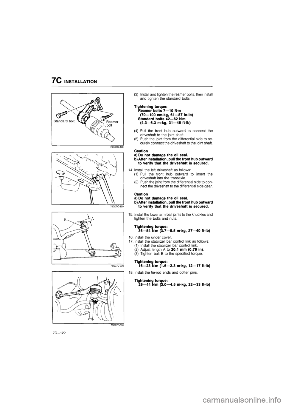
(3) Install and tighten the reamer bolts, then install
and tighten the standard bolts.
Tightening torque:
Reamer bolts 7—10 N-m
(70—100 cm-kg, 61—87 in-lb)
Standard bolts 42—62 N m
(4.3—6.3 m-kg, 31—46 ft-lb)
(4) Pull the front hub outward to connect the
driveshaft to the joint shaft.
(5) Push the joint from the differential side to se-
curely connect the driveshaft to the joint shaft.
Caution
a) Do not damage the oil seal.
b) After installation, pull the front hub outward
to verify that the driveshaft is secured.
Install the left driveshaft as follows:
(1) Pull the front hub outward to insert the
driveshaft into the transaxle.
(2) Push the joint from the differential side to con-
nect the driveshaft to the differential side gear.
Caution
a) Do not damage the oil seal.
b) After installation, pull the front hub outward
to verify that the driveshaft is secured.
Install the lower arm ball joints to the knuckles and
tighten the bolts and nuts.
Tightening torque:
36—54 N-m (3.7—5.5 m-kg, 27—40 ft-lb)
Install the under cover.
Install the stabilizer bar control link as follows:
(1) Install the stabilizer bar control link.
(2) Adjust length A to 20.1 mm (0.79 in).
(3) Tighten bolt B to the specified torque.
Tightening torque:
16—23 N-m (1.6—2.3 m-kg, 12—17 ft-lb)
Install the tie-rod ends and cotter pins.
Tightening torque:
29—44 N-m (3.0—4.5 m-kg, 22—33 ft-lb)
7C-122
Page 1280 of 1865
DRIVESHAFT 9
[MTX]
DISASSEMBLY
Disassemble in the sequence shown in the figure referring to the disassembly note for specially marked
parts.
Note
a) Clamp the shaft in a vice. Use protectors in the vice to avoid damage.
b)Do not allow dirt or foreign matter in the joint during disassembly or assembly.
c) Do not disassemble the ball-joint at the wheel side. Do not wipe the grease off if there
is no problem.
d)Do not remove the clip used to secure the outer ring to the ball-joint at the differential
side if there is no problem.
If the clip is removed, replace it with a new one.
1. Boot band
2. Clip
3. Outer ring
4. Snap ring
86U09X-059
5. Ball joint
6. Boot band
7. Boot
8. Clip
9. Sensor rotor (Refer to Section 11)
Clip
1. Make matching marks on the driveshaft and out-
er ring for proper reassembly.
Note
Mark with paint, do not use a punch.
2. Remove the clip.
86U09X-091
9-31
Page 1282 of 1865
DRIVESHAFT 9
ASSEMBLY
Boot
Wrap the shaft splines with tape before installing the
boot.
86U09X-093
Wheel side
Note
a) The wheel side arid differential side boots
are different as shown in the figure.
b) Fill the inside of the ball joint with the speci-
fied grease included in the kit.
c) Securely fit the boot to the shaft and the
outer race boot grooves.
86U09X-062
Balls, inner ring and cage
1. Align the matching marks and install the balls.
86U09X-094
2. Apply molybdenum disulfide grease to the joint.
Note
Do not use other than specified grease.
86U09X-095
9-33
Page 1285 of 1865
9 DRIVESHAFT
INSPECTION
Check and replace any faulty parts.
1. Twisted, bent, or damaged shaft.
2. Wear or scoring of splines.
3. Wear, excessive looseness, seizure, rust, or dam-
age of bearing.
4. Checking, damage, or deterioration of boots.
5. Excessive play or heat damage of joint shaft
bearing.
86U09X-066
Wheel side Differential side
86U09X-067
ASSEMBLY
Assemble in the reverse order of disassembly, refer-
ring to assembly note.
Assembly Note
Note
a) The wheel side and differential side boots
are different as shown in the figure.
b) Fill the inside of the ball joint with the speci-
fied grease included in the kit.
c) Securely fit the boot to the shaft and the
outer race boot grooves.
Tripod joint
Install the snap ring to the joint.
86U09X-068
Clip
Install a new clip.
86U09X-069
9-36
Page 1307 of 1865
TIE-ROD END BOOT 1 0
86U10X-030
Removal Note
Tie-rod end
Separate the tie-rod end from the knuckle using the
SST
69G10X-039
Nut
Before removing the nut from the tie-rod end, make
a mark for reference during installation.
Boot
Secure the tie-rod end in a vise. Place a chisel against
the boot and hold it at the angle shown. Remove the
boot by tapping with a hammer.
Caution
Be careful not to scar the part where the boot
is attached to the tie-rod end.
86U10X-031
10—19
Page 1337 of 1865
MANUAL STEERING 1 0
Disassembly Note
Steering gear and linkage
Secure the gear and linkage in a vise.
Caution
Insert protective material (such as copper
plates) in the jaws of the vise.
86U10X-089
Tie-rod ends
Before removing the tie-rod ends, make a mark for
proper installation.
86U10X-090
Tie-rods
Remove the tie-rods.
1. Uncrimp the washer as shown in the figure.
86U10X-091
2. Secure the rack in a vise and remove the tie-rod.
86U10X-092
10—49
Page 1344 of 1865

10 MANUAL STEERING
86U10X-115
86U10X-116
86U10X-117
Dust Cover
)
2
Oil seal
is Nm
sn n
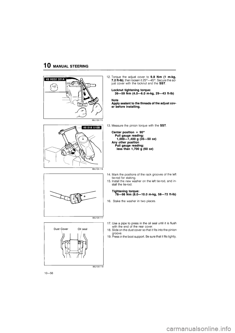
12. Torque the adjust cover to 9.8 N-m (1 m-kg,
7.2 ft-lb), then loosen it 25°—45°. Secure the ad-
just cover with the locknut and the SST.
Locknut tightening torque:
39—59 N-m (4.0—6.0 m-kg, 29—43 ft-lb)
Note
Apply sealant to the threads of the adjust cov-
er before installing.
13. Measure the pinion torque with the SST.
Center position ± 90°
Pull gauge reading:
1,000—1,400 g (35—50 oz)
Any other position
Pull gauge reading:
less than 1,700 g (60 oz)
14. Mark the positions of the rack grooves of the left
tie-rod for staking.
15. Install the new washer on the left tie-rod, and in-
stall the tie-rod.
Tightening torque:
78—98 N-m (8.0—10.0 m-kg, 58—72 ft-lb)
16. Stake the washer in two places.
17. Use a pipe to press in the oil seal until it is flush
with the end of the rear cover.
18. Slide on the dust cover so that it fits into the pinion
groove.
19. Press in the boot support. Be sure that it fits tightly.
86U10X-118
10—56