Page 1390 of 1865
1 0 ELECTRICAL COMPONENTS OF 4-WHEEL STEERING
flashes
Replace control unit
4WS-9 Failure of control unit, alternator, or wiring harness
Start engine,
I
Check voltage between terminal of control unit con-nector and body ground.
Terminal Voltage
G(B) OV
H (B) OV
K(G) Approx. 12V
L (G) Approx. 12V
N(B) OV
OK
NG
Check 4WS relay and timer (Refer to page 10—103) -
OK
Check battery, harness, and alternator.
NG
Turn ignition switch OFF. Start engine. Check if 4WS warning light flashes or illuminates.
NO
Momentary problem (If warning light often flashes or illuminates, check battery and alter-nator. Replace control unit if necessary).
YES
Replace control unit.
Replace relay and timer
76G10X-031
4WS WARNING LIGHT
1. Turn the ignition switch OFF.
2. Turn the ignition switch ON, and check that the
4WS warning light illuminates.
3. If there is no illumination, check the warning light
bulb and wiring harness.
Replace the control unit if necessary.
86U10X-232
10-102
Page 1479 of 1865

ANTI-LOCK BRAKE SYSTEM (ABS) 1 1
86U11X-1C
Q-08
Q-08
Fail-safe relay
B B BG
(Q-08)(Q-09)
V
BL BR
Motor relay
B BR (Q-09)
LO RY
View from male-pin side
86U11X-167
76G11X-096
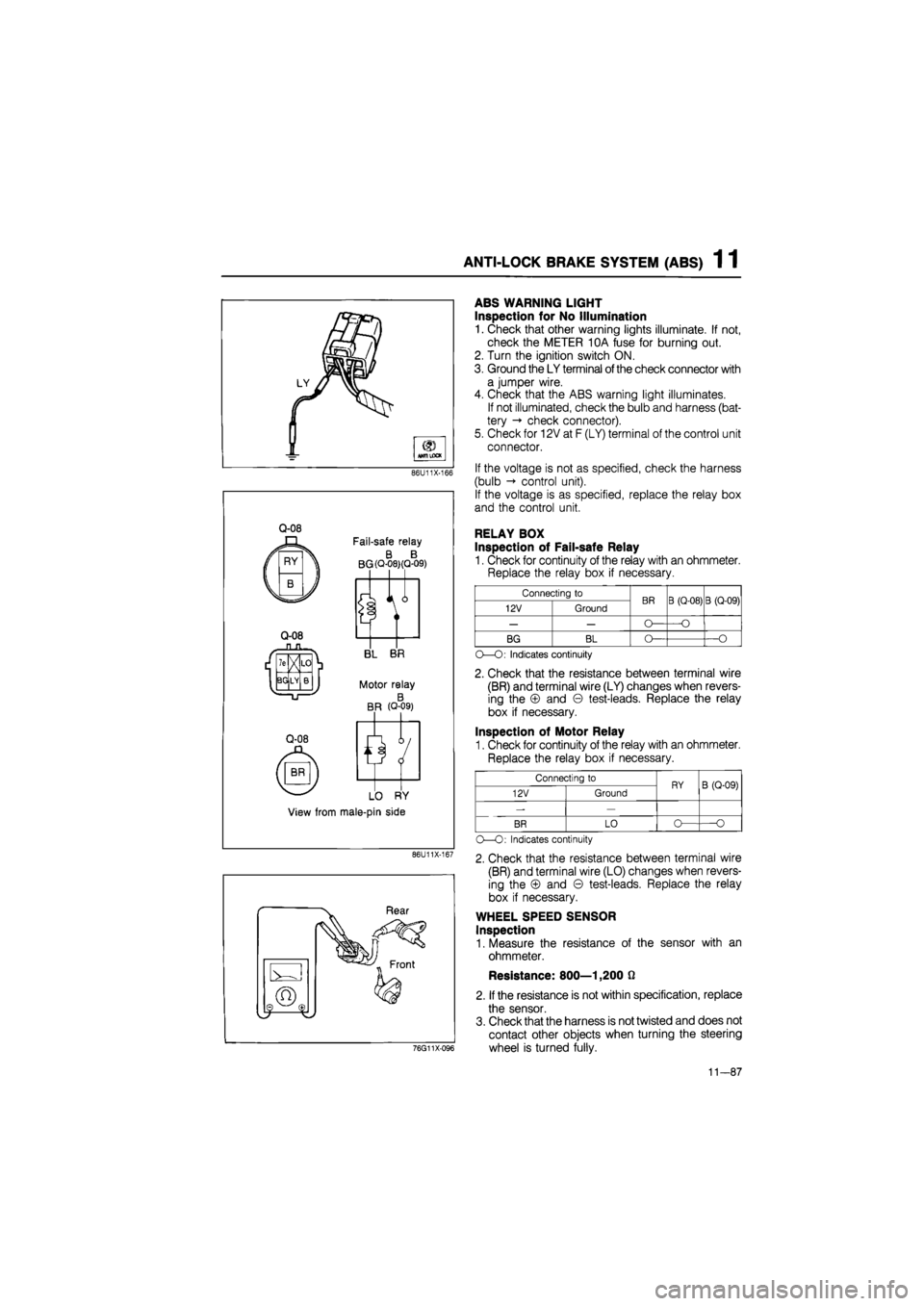
ABS WARNING LIGHT
Inspection for No Illumination
1. Check that other warning lights illuminate. If not,
check the METER 10A fuse for burning out.
2. Turn the ignition switch ON.
3. Ground the LY terminal
of
the check connector with
a jumper wire.
4. Check that the ABS warning light illuminates.
If not illuminated, check the bulb and harness (bat-
tery -» check connector).
5. Check for 12V at F (LY) terminal of the control unit
connector.
If the voltage is not as specified, check the harness
(bulb control unit).
If the voltage is as specified, replace the relay box
and the control unit.
RELAY BOX
Inspection of Fail-safe Relay
1. Check for continuity of the relay with an ohmmeter.
Replace the relay box if necessary.
Connecting to BR B (Q-08) B (Q-09) 12V Ground BR B (Q-08) B (Q-09)
— — O— —O
BG BL O— —O
O—O: Indicates continuity
2. Check that the resistance between terminal wire
(BR) and terminal wire (LY) changes when revers-
ing the © and © test-leads. Replace the relay
box if necessary.
Inspection of Motor Relay
1. Check for continuity of the relay with an ohmmeter.
Replace the relay box if necessary.
Connecting to RY B (Q-09) 12V Ground RY B (Q-09)
-—
BR LO o— O
O—O: Indicates continuity
2. Check that the resistance between terminal wire
(BR) and terminal wire (LO) changes when revers-
ing the © and © test-leads. Replace the relay
box if necessary.
WHEEL SPEED SENSOR
Inspection
1. Measure the resistance of the sensor with an
ohmmeter.
Resistance: 800—1,200 0
2. If the resistance is not within specification, replace
the sensor.
3. Check that the harness is not twisted and does not
contact other objects when turning the steering
wheel is turned fully.
11-87
Page 1579 of 1865
1 4 HEADLIGHT AND COMBINATION LIGHT
HEADLIGHT AND COMBINATION LIGHT
REMOVAL AND INSTALLATION
1. Disconnect the negative battery cable.
2. Remove in the sequence shown in the figure, referring to removal note for the specially marked parts.
3. Install in the reverse order of removal.
76G14X-005
1. Screw
2. Turn signal light assembly
3. Screw
4. Radiator grille
5. Bolts
6. Bolts
7. Headlight assembly
8. Screws
9. Light garnish
10. Headlight bulb
60 + 55W/55W
11. Parking light bulb 5W
12. Turn signal light bulb
21W
14—28
Page 1580 of 1865
HEADLIGHT AND COMBINATION LIGHT 1 4
76G14X-006
1. Screw 6. Bolts
2. Turn signal light assembly 7. Fastener
3. Screw 8. Screw
4. Radiator grille 9. Light garnish
5. Bolts 10. Headlight assembly
11. Headlight bulb
60 + 55/55W
12. Parking light bulb 5W
13. Turn signal light bulb
21W
14—29
Page 1583 of 1865
1 4 REAR COMBINATION LIGHTS
REAR COMBINATION LIGHTS
REMOVAL AND INSTALLATION
1. Disconnect the negative battery cable.
2. Remove in the sequence shown in the figure.
3. Install in the reverse order of removal.
76G14X-010
Hatchback
1. End trim
2. Nuts
3. Lens and body
4. Cover
5. Bulb: Turn signal light 21W
Brake and tail light 21W
Side marker light 5W
Sedan and Coupe/MX-6
1. End trim
2. Nuts
3. Lens and body
4. Cover
5. Bulb: Turn signal light 21W
Brake and tail light 21W
Side marker light 5W
14—32
Page 1586 of 1865
LICENSE PLATE
LIGHT
AND CORGO ROOM LIGHT
1
4
LICENSE PLATE LIGHT AND CORGO ROOM LIGHT
REMOVAL AND INSTALLATION
1. Disconnect the negative battery cable.
2. Remove in the sequence shown in the figure.
3. Install in the reverse order of removal.
76G14X-011
Sedan and Coupe/MX-6
License plate light
1. Screws
2. Lens
3. Bulb 5W x 2
Back up light
4. End trim
5. Bulb 21W
6. Nuts
7. Rear finisher
Hatchback
Corgo room light
1. Lens
2. Switch and bulb assembly 5W
License plate light
3. Side trim
4. Lower trim
5. End trim
6. Screws
7. Lens
8. Bulb 5W x 2
9. Rear finisher
14-35
Page 1587 of 1865
1 4 INTERIOR
LIGHT AND
MAP LIGHT
INTERIOR LIGHT AND MAP LIGHT
REMOVAL AND INSTALLATION
1. Disconnect the negative battery cable.
2. Remove in the sequence shown in the figure.
3. Install in the reverse order of removal.
Map light
86U14X-082
Interior Light Map Light
1. Lens 1. Lens
2. Bulb 10W 2. Bulb 8W
14-36
Page 1657 of 1865

15 INTRODUCTION
INTRODUCTION
HOW TO USE THIS SECTION
Information regarding removal and installation of electrical equipment is given in SECTION 14.
Understanding will be easier if this section is used in conjunction with the WIRING DIAGRAMS.
63U15X-002
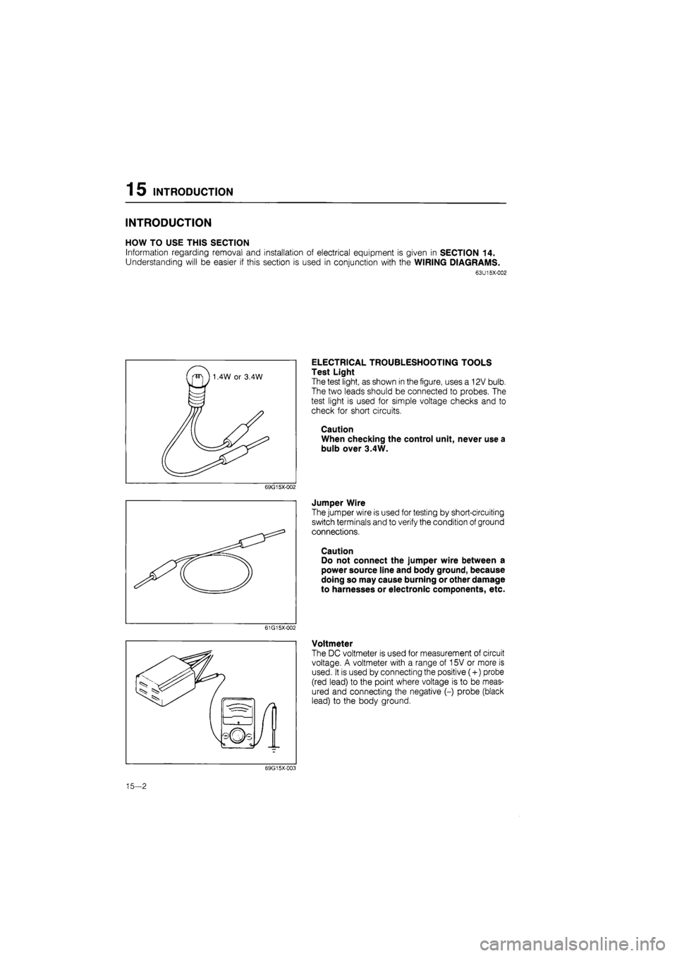
ELECTRICAL TROUBLESHOOTING TOOLS
Test Light
The test light, as shown in the figure, uses a 12V bulb.
The two leads should be connected to probes. The
test light is used for simple voltage checks and to
check for short circuits.
Caution
When checking the control unit, never use a
bulb over 3.4W.
69G15X-002
Jumper Wire
The jumper wire is used for testing by short-circuiting
switch terminals and to verify the condition of ground
connections.
Caution
Do not connect the jumper wire between a
power source line and body ground, because
doing so may cause burning or other damage
to harnesses or electronic components, etc.
61G15X-002
Voltmeter
The DC voltmeter is used for measurement of circuit
voltage. A voltmeter with a range of 15V or more is
used. It is used by connecting the positive (+) probe
(red lead) to the point where voltage is to be meas-
ured and connecting the negative (-) probe (black
lead) to the body ground.
69G15X-003
15—2