1987 MAZDA 626 bulb
[x] Cancel search: bulbPage 1692 of 1865
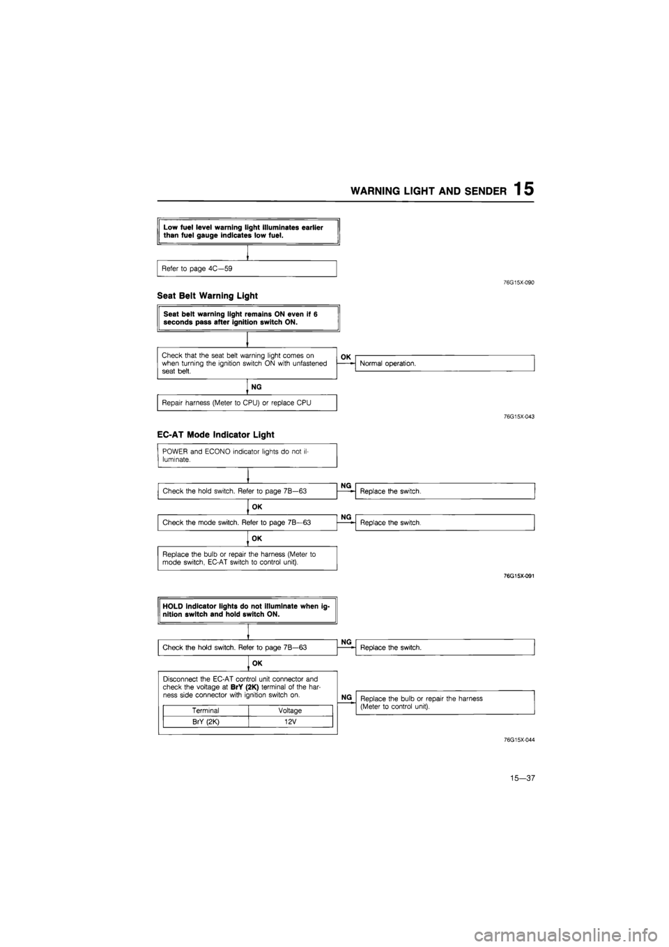
WARNING LIGHT AND SENDER 1 5
76G15X-090
Seat Belt Warning Light
76G15X-043
EC-AT Mode Indicator Light
POWER and ECONO indicator lights
do
not
il-
luminate.
NG
Check the hold switch. Refer
to
page 7B—63
NG
Replace the switch.
OK
NG
Check the mode switch. Refer
to
page 7B—63
NG
Replace the switch.
fOK
Replace the bulb
or
repair the harness (Meter
to
mode switch, EC-AT switch
to
control unit).
76G15X-091
76G15X-044
15—37
Page 1693 of 1865
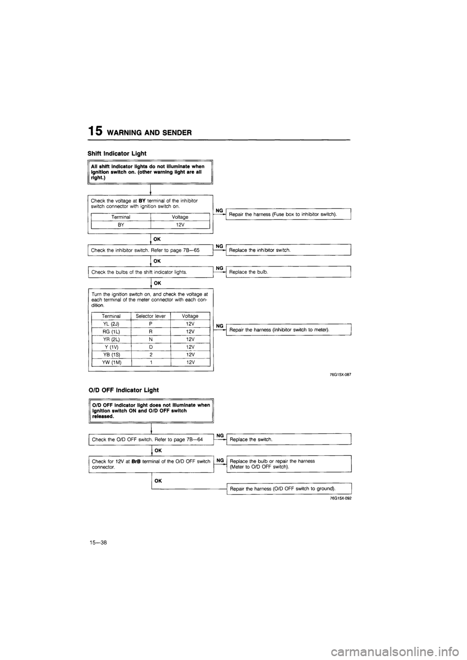
1 5 WARNING AND SENDER
Shift Indicator Light
All shift indicator lights do not Illuminate when ignition switch on. (other warning light are all right.)
Check the voltage
at BY
terminal
of
the inhibitor switch connector with ignition switch
on.
Terminal Voltage
BY 12V
NG
Repair the harness (Fuse box
to
inhibitor switch).
OK
Check the inhibitor switch. Refer
to
page 7B—65
NG
Replace the inhibitor switch. Check the inhibitor switch. Refer
to
page 7B—65 Replace the inhibitor switch.
OK
NG
Check the bulbs
of
the shift indicator lights.
NG
Replace the bulb.
OK
Turn the ignition switch on, and check the voltage
at
each terminal
of
the meter connector with each con-dition.
Terminal Selector lever Voltage
YL (2J) P 12V
RG (1L) R 12V
YR (2L) N 12V
Y(1V) D 12V
YB (1S) 2 12V
YW (1M) 1 12V
NG
Repair the harness (Inhibitor switch
to
meter).
76G15X-087
O/D OFF Indicator Light
OK
Repair the harness (O/D OFF switch
to
ground).
76G15X092
15-38
Page 1701 of 1865
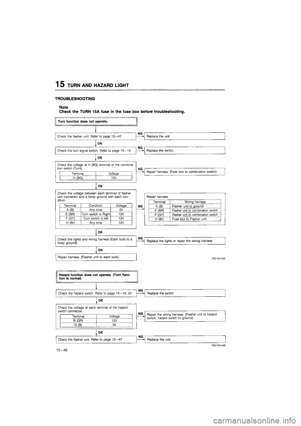
1 5 TURN AND HAZARD LIGHT
TROUBLESHOOTING
Note
Check the TURN 15A fuse in the fuse box before troubleshooting.
Terminal Voltage
H (BG) 12V
OK
Check the voltage between each terminal
of
flasher unit connector and
a
body ground with each con-dition.
Terminal Condition Voltage
A(B) Any time OV
E (BR) Turn switch
is
Riaht 12V
F (GY) Turn switch
is
left 12V
H (Br) Anv time 12V
OK
Turn function does not operate.
Check the flasher unit. Refer
to
page 15—47
OK
Check the turn signal switch. Refer
to
page 15—14
OK
NG
NG
Check the voltage
at H
(BG) terminal
of
the combina-tion switch (Turn).
Replace the unit.
Replace the switch.
NG
Repair harness. (Fuse box
to
combination switch)
Repair harness.
NG
Terminal Wiring harness
A (B) Flasher unit
to
ground
E (BR) Flasher unit
to
combination switch
F (GY) Flasher unit
to
combination switch
H (Bri Fuse box
to
Flasher unit
Check the lights and wiring harness (Each bulb
to a
body ground)
NG
Replace the lights
or
repair the wiring harness.
OK
Repair harness. (Flasher unit
to
each bulb)
76G15X-045
Hazard function does not operate. (Turn func-tion is normal)
Check the hazard switch. Refer
to
page 15—19,
20
OK
NG
Replace the switch.
Check the voltage
at
each terminal
of
the hazard
switch connector.
Terminal Voltage
B (GR) 12V
D (B) OV
15-46
NG
Repair the wiring harness. (Flasher unit
to
hazard
switch, hazard switch
to
ground)
OK
Check the flasher unit. Refer
to
page 15—47
NG
Replace the unit.
76G15X-046
Page 1702 of 1865
TURN AND HAZARD LIGHT 1 5
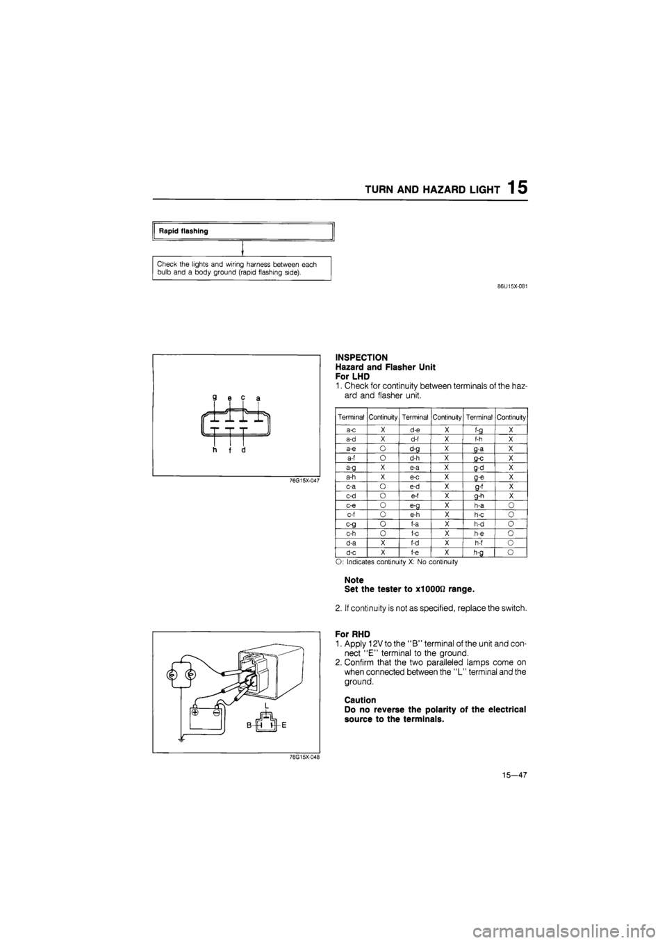
Rapid flashing
Check the lights and wiring harness between each
bulb and
a
body ground (rapid flashing side).
86U15X-081
76G15X-047
INSPECTION
Hazard and Flasher Unit
For LHD
1. Check for continuity between terminals of the haz-
ard and flasher unit.
Terminal Continuity Terminal Continuity Terminal Continuity
a-c X d-e X f-g X
a-d X d-f X f-h X
a-e O d-g X g-a X
a-f O d-h X g-c X
a-g X e-a X g-d X
a-h X e-c X g-e X
c-a
o
e-d X 9-f X
c-d
o
e-f X g-h X
c-e
o
e-g X h-a
O
c-f
o
e-h X h-c
o
c-g
o
f-a X h-d
o
c-h
o
f-c X h-e
o
d-a X f-d X h-f
o
d-c X f-e X h-g
o
O: Indicates continuity
X: No
continuity
Note
Set the tester to X1000Q range.
2. If continuity is not as specified, replace the switch.
For RHD
1. Apply 12V to the "B" terminal of the unit and con-
nect "E" terminal to the ground.
2. Confirm that the two paralleled lamps come on
when connected between the "L" terminal and the
ground.
Caution
Do no reverse the polarity of the electrical
source to the terminals.
76G15X048
15—47
Page 1705 of 1865
1 5 STOP LIGHT
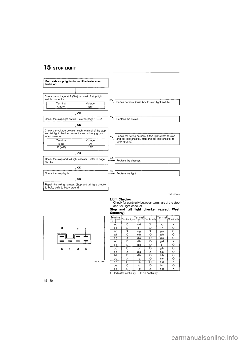
Both side stop lights do not illuminate when brake on.
Check the voltage
at A
(GW) terminal
of
stop light switch connector.
NG
Terminal Voltage
A (GW) 12V
Repair harness. (Fuse box
to
stop light switch)
OK
Check the stop light switch. Refer
to
page 15—51
NG
Replace the switch.
OK
Check the voltage between each terminal
of
the stop and tail light checker connector and
a
body ground when brake
on.
Terminal Voltage
B(B) OV
C (WG) 12V
NG Repair the wiring harness. (Stop light switch
to
stop and tail light checker, stop and tail light checker
to
body ground)
OK
OK
Repair the wiring harness. (Stop and tail light checker to bulb, bulb
to
body ground)
76G15X-049
Light Checker
1. Check for continuity between terminals of the stop
and tail light checker.
Stop and tail light checker (except West
Germany)
3 c £
r -r •
I i f 1 3
76G15X050
Terminal Continuity Terminal Continuity Terminal Continuity
i + i -
Continuity
+
1
-
Continuity
i + i -
Continuity
a-b
O
c-d
X
f-a
X
a-c
O
c-f
o
f-h
0
a-d
X c-g X g-a o
a-f
o
c-h
o
g-b
o
a-a
X
d-a
o a-c o
a-h
o
d-b
o
g-d
X
b-a
o
d-c
0
a-f
o
b-c
o
d-f
o
g-h
o
b-d
X
d-g
X
h-a
o
b-f
o
d-h
o
h-b
o
b-g
X
f-a
0
h-c
o
b-h
o
f-b
o
h-d
X
c-a
0
f-c
o
h-f
o
c-b
o
f-d
X
h-a
X
O: Indicates continuity
X: No
continuity
15-50
Page 1710 of 1865
HEADLIGHT 15
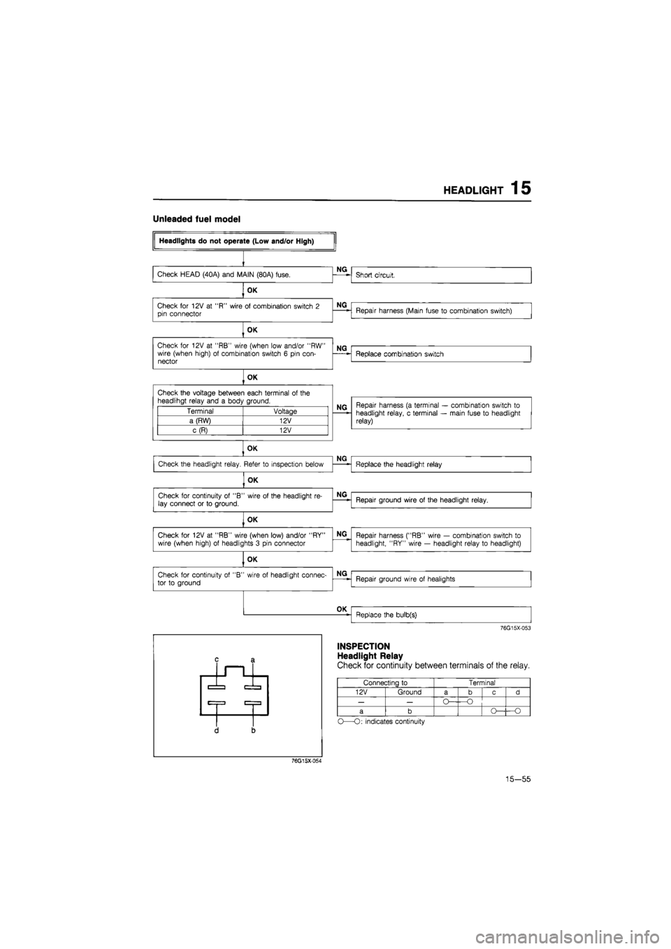
Unleaded fuel model
OK
Check
for
12V
at
"RB" wire (when low and/or "RW" wire (when high)
of
combination switch
6
pin con-nector
NG
Check
for
12V
at
"RB" wire (when low and/or "RW" wire (when high)
of
combination switch
6
pin con-nector
NG
Replace combination switch
Check
for
12V
at
"RB" wire (when low and/or "RW" wire (when high)
of
combination switch
6
pin con-nector
OK
Check the voltage between each terminal
of
the headlihgt relay and
a
body ground.
Terminal Voltage
a (RW) 12V
c(R) 12V
NQ Repair harness
(a
terminal
—
combination switch
to
headlight relay,
c
terminal
—
main fuse
to
headlight relay)
OK
OK —
Replace the bulb(s)
76G15X-053
INSPECTION
Headlight Relay
Check for continuity between terminals of the relay.
Connecting
to
Terminal
12V Ground a b c d
— —
O— —O
a b O— —-O
O—O: indicates continuity
76G15X-054
15—55
Page 1788 of 1865
OUTLINE 16
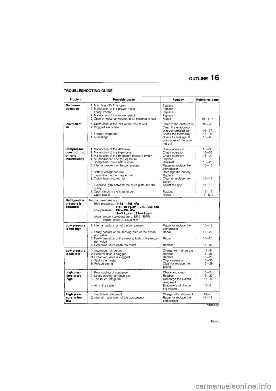
TROUBLESHOOTING GUIDE
Problem Probable cause Remedy Reference page
No blower
1. Main fuse (30
A) is
open Replace
operation
2 Malfunction
of
the blower motor Replace 3. Faulty resistor Replace 4. Malfunction
of
the blower switch Replace 5. Open
or
loose connection
in an
electrical circuit Repair 16—6,
7
Insufficient
1. Obstruction
in
the inlet
of
the blower unit Remove the obstruction 16-26
air
2. Clogged evaporator Clean the evaporator
with compressed
air
16-27 3. Frosted evaporator Check the thermostat 16-30 4. Air leakage Check for leakage
at
16-26 both sides
of
the cool-
ing unit
Compressor
1. Malfunction
of
the A/C relay Check operation 16—30
does not run,
2. Malfunction
of
the thermostat Check operation 16—30
or runs
3. Malfunction
of
the refrigerant-pressure switch Check operation 16—31
insufficiently
4.
Air
conditioner fuse (15
A)
failure Replace 5. Compressor drive belt
is
loose Readjust 16—23
6. Internal problem
of
the compressor Repair
or
replace
the
16—13
compressor 7. Battery voltage too low Recharge the battery 8. Layer short
in
the magnet coil Replace 9. Clutch face dirty with
oil
Clean
or
replace the 16-13
clutch 10. Excessive gap between the drive plate and
the
Adjust the gap 16-13
pulley
11. Open circuit
in
the magnet coil Replace 16—13
12 Open circuit Repair 16-6,
7
Refrigeration
Normal pressures are:
pressure is
High pressure
1472—1765 kPa
abnormal (15—18 kg/cm2, 214—255 psi)
Low pressure
197—294 kPa
(2—3 kg/cm2, 29—42 psi)
when: ambient temperature 35°C (95°F)
engine speed 1,500
rpm
Low pressure
1. Internal malfunction
of
the compressor Repair
or
replace the 16-13
is too high
compressor
2. Faulty contact
of
the sensing bulb
of
the expan-Repair 16-26
sion valve 3. Faulty insulation
of
the sensing bulb
of
the expan-Repair 16—26
sion valve
4. Expansion valve open too much Replace 16—26
Low pressure
1. Insufficient refrigerant Charge with refrigerant 16-8
is too low
2. Receiver-drier
is
clogged Replace 16-25
3. Expansion valve
is
clogged Replace 16-26
4. Faulty thermostat Check operation 16-30 5. Frosted piping Clean
or
replace the 16—29
piping
High pres-
1. Poor cooling
of
condenser Check and clean 16-24
sure is too
2. Loose cooling fan drive belt Readjust 16—23
high
3. Too much refrigerant Discharge the excess 16-8
refrigerant 4.
Air in
the system Evacuate and charge 16-8
the system
High pres-
1. Insufficient refrigerant Charge with refrigerant 16-8
sure is too
2. Internal malfunction
of
the compressor Repair
or
replace the 16-13
low
compressor
76G16X-004
16—5
Page 1795 of 1865
16 OUTLINE
Thermometer (Dry)
Thermometer
(Dry & Wet)
76G16X-633
69G16X-024
DETERMINING THE RELATIVE HUMI-DITY: Read the temperatures of the dry- and v^et-bulb thermometers at the air inlet (evapo-rator inlet). Then bring them into mutual relation on the chart and determine the intersection, which is the relative humidity^ For exampie, if the dry-bulb temperature^ is 90° F. and the wet-bulb temper- ^ ature is 78° F, the relative humidity is ^ 60%.
DRV BUL8 TEMPERATURE
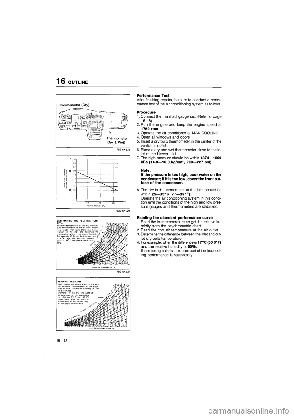
Performance Test
After finishing repairs, be sure to conduct a perfor-
mance test of the air conditioning system as follows.
Procedure
1. Connect the manifold gauge set. (Refer to page
16-8)
2. Run the engine and keep the engine speed at
1750 rpm.
3. Operate the air conditioner at MAX COOLING.
4. Open all windows and doors.
5. Insert a dry-bulb thermometer in the center of the
ventilator outlet.
6. Place a dry and wet thermometer close to the in-
let of the blower inlet.
7. The high pressure should be within 1374—1569
kPa (14.0—16.0 kg/cm2, 200—227 psi).
Note:
If the pressure is too high, pour water on the
condenser; if it is too low, cover the front sur-
face of the condenser.
8. The dry-bulb thermometer at the inlet should be
within 25—35°C (77—95°F).
Operate the air conditioning system in this condi-
tion until the conditions of the high and low pres-
sure gauges and thermometers are stabilized.
Reading the standard performance curve
1. Read the inlet temperature an get the relative hu-
midity from the psychrometric chart.
2. Read the cool air temperature at the air outlet.
3. Determine the difference between the inlet and out-
let dry-bulb temperature.
4. For example, when the difference is 17°C (30.6°F)
and the relative humidity is 60%:
If
the closing point is the upper part of the line, cool-
ing performance is satisfactory.
76G16X-634
READING THE GRAPH: After reading the temperatures of the wet-and dry-bulb thermometers at the evapo-rator air inlet, the relative humidity (%} can be determined Example: If the dry- and wet-bulb temperatures at the evaporator air inlet are 25°
C
and 19 5°C respectively, find the point of intersection of the dotted lines in the graph, which is
• i
•.p-I--!1. fi -GL^TIULB ': "'.L .T.L CL
16—12