Page 7 of 1865
FUNDAMENTAL PROCEDURES G
Depending on where they are;
1. Sealant should be applied to gaskets
2. Oil should be applied to the moving components
of parts
3. Specified oil or grease should be applied at the
prescribed locations (oil seals, etc.) before as-
sembly.
47U0GX-012
ADJUSTMENTS
Use suitable gauges and/or testers when making var-
ious adjustments.
67U0GX-002
ELECTRICAL SYSTEM
Be sure to disconnect the battery cable from the nega-
tive (-) terminal of the battery.
Never pull on the wiring when disconnecting con-
nectors.
When locking connectors, make sure to listen for a
click that will let you know they are securely locked.
Handle sensors and relays carefully. Be careful not
to drop them or strike them against other parts.
47U0GX-014
RUBBER PARTS AND TUBING
Always prevent gasoline or oil from getting on rub-
ber parts or tubing.
47U0GX-015
G—5
Page 662 of 1865

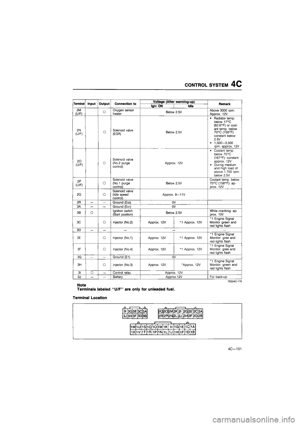
CONTROL SYSTEM 4C
Terminal Input Output Connection to Voltage (After warming-up) Remark Terminal Input Output Connection to Ign: ON Idle Remark
2M
(U/F) o Oxygen sensor
heater Below 2.5V Above 3000 rpm: Approx. 12V
2N
(U/F) o Solenoid valve (EGR) Below 2.5V
• Radiator temp, below 17°C (62.6°F) or cool-ant temp, below 70°C (158°F): constant below 2.5 V
• 1,500-3,500 rpm: approx. 12V
20 (U/F) 0 Solenoid valve (No.2 purge control) Approx. 12V
• Coolant temp, below 75 °C (167°F): constant approx. 12V
• During medium and high load of above 1,700 rpm: below 2.5V
2P
(U/F) o
Solenoid valve
(No.1 purge
control)
Below 2.5V
Coolant temp, below 70°C (158°F): ap-prox. 12V
2Q o Solenoid valve (Idle speed control) Approx. 9—11V
2R — — Ground (E02) OV
3A — — Ground (E01) OV
3B O Ignition switch
(Start position) Below 2.5V While cranking: ap-
Drox. 10V
3C o Injector (No.2) Approx. 12V *1 Approx. 12V
*1 Engine Signal Monitor green and red liahts flash
3D — — — — —
3E o Injector (No.1) Approx. 12V *1 Approx. 12V
*1 Engine Signal
Monitor: gree and
red liahts flash
3F 0 Injector (No.4) Approx. 12V *1 Approx. 12V
*1 Engine Signal Monitor: gree and red liahts flash
3G — Ground (E1) OV
3H o Injector (No.3) Approx. 12V 'Approx. 12V *1 Engine Signal
Monitor: green and
red lights flash
31 0 — Control relav ADDrox. 12V
3J — — Battery Approx. 12V For back-uD
76G04C-179
Note
Terminals labeled "U/F" are only for unleaded fuel.
Terminal Location
31 3G 3E 3C 3A
3J 3H 3F 3D 3B
2Q 2d 2M *
L
CM
2G 2E 2C <
CM
2R 2P 2N 2L 2J 2H 2F 20 2B
1W 1U 1S 1Q 10 1M 1K 11 1G 1E 1C 1A
1X 1V 1T 1R 1P 1N 1L 1J 1H 1F 1D 1B
4C-101
Page 707 of 1865

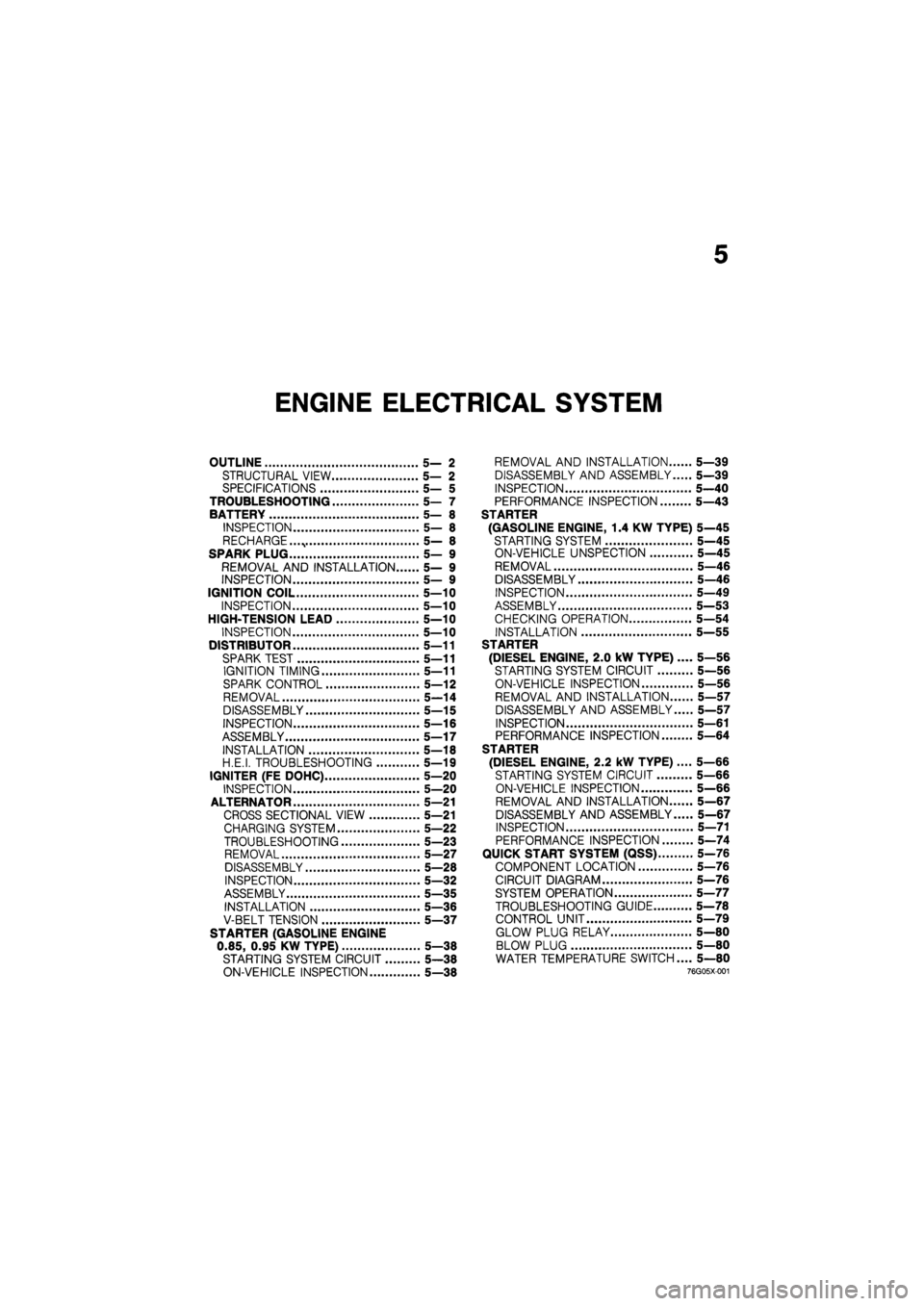
5
ENGINE ELECTRICAL SYSTEM
OUTLINE 5— 2
STRUCTURAL VIEW 5— 2
SPECIFICATIONS 5— 5
TROUBLESHOOTING 5— 7
BATTERY 5— 8
INSPECTION 5— 8
RECHARGE. 5— 8
SPARK PLUG 5— 9
REMOVAL AND INSTALLATION 5— 9
INSPECTION 5— 9
IGNITION COIL 5—10
INSPECTION 5—10
HIGH-TENSION LEAD 5—10
INSPECTION 5—10
DISTRIBUTOR 5—11
SPARK TEST 5—11
IGNITION TIMING 5—11
SPARK CONTROL 5—12
REMOVAL 5—14
DISASSEMBLY 5—15
INSPECTION 5—16
ASSEMBLY 5—17
INSTALLATION 5—18
H.E.I. TROUBLESHOOTING 5—19
IGNITER (FE DOHC) 5—20
INSPECTION 5—20
ALTERNATOR 5—21
CROSS SECTIONAL VIEW 5—21
CHARGING SYSTEM 5—22
TROUBLESHOOTING 5—23
REMOVAL 5—27
DISASSEMBLY 5—28
INSPECTION 5—32
ASSEMBLY 5—35
INSTALLATION 5—36
V-BELT TENSION 5—37
STARTER (GASOLINE ENGINE
0.85, 0.95 KW TYPE) 5—38
STARTING SYSTEM CIRCUIT 5—38
ON-VEHICLE INSPECTION 5—38
REMOVAL AND INSTALLATION 5—39
DISASSEMBLY AND ASSEMBLY 5—39
INSPECTION 5—40
PERFORMANCE INSPECTION 5—43
STARTER
(GASOLINE ENGINE, 1.4 KW TYPE) 5—45
STARTING SYSTEM 5—45
ON-VEHICLE UNSPECTION 5—45
REMOVAL 5—46
DISASSEMBLY 5—46
INSPECTION 5—49
ASSEMBLY 5—53
CHECKING OPERATION 5—54
INSTALLATION 5—55
STARTER
(DIESEL ENGINE, 2.0 kW TYPE) .... 5—56
STARTING SYSTEM CIRCUIT 5—56
ON-VEHICLE INSPECTION 5—56
REMOVAL AND INSTALLATION 5—57
DISASSEMBLY AND ASSEMBLY 5—57
INSPECTION 5—61
PERFORMANCE INSPECTION 5—64
STARTER
(DIESEL ENGINE, 2.2 kW TYPE).... 5—66
STARTING SYSTEM CIRCUIT 5—66
ON-VEHICLE INSPECTION 5—66
REMOVAL AND INSTALLATION 5—67
DISASSEMBLY AND ASSEMBLY 5—67
INSPECTION 5—71
PERFORMANCE INSPECTION 5—74
QUICK START SYSTEM (QSS) 5-76
COMPONENT LOCATION 5—76
CIRCUIT DIAGRAM 5—76
SYSTEM OPERATION 5—77
TROUBLESHOOTING GUIDE 5—78
CONTROL UNIT 5—79
GLOW PLUG RELAY 5—80
BLOW PLUG 5—80
WATER TEMPERATURE SWITCH.... 5—80
76g05x-001
Page 1465 of 1865

ANTI-LOCK BRAKE SYSTEM (ABS) 1 1
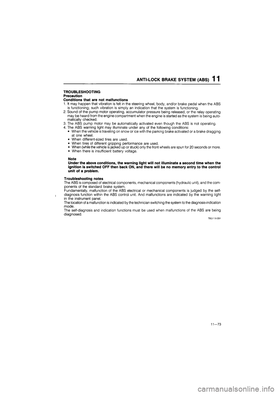
TROUBLESHOOTING
Precaution
Conditions that are not malfunctions
1. It may happen that vibration is felt in the steering wheel, body, and/or brake pedal when the ABS
is functioning; such vibration is simply an indication that the system is functioning.
2. Sound of the pump motor operating, accumulator pressure being released, or the relay operating
may be heard from the engine compartment when the engine is started as the system is being auto-
matically checked.
3. The ABS pump motor may be automatically activated even though the ABS is not operating.
4. The ABS warning light may illuminate under any of the following conditions:
• When the vehicle is traveling on snow or ice with the parking brake activated or a brake dragging
at one wheel.
• When different-sized tires are used.
• When tires of different gripping performance are used.
• When (while the vehicle is jacked up or stuck) only the front wheels are spun for 20 seconds or more.
• When there is insufficient battery voltage.
Note
Under the above conditions, the warning light will not illuminate a second time when the
ignition is switched OFF then back ON, and there will be no memory entry to the control
unit of a problem.
Troubleshooting notes
The ABS is composed of electrical components, mechanical components (hydraulic unit), and the com-
ponents of the standard brake system.
Fundamentally, malfunction of the ABS electrical or mechanical components is judged by the self-
diagnosis function within the ABS control unit. And malfunctions are indicated by the warning light
in the instrument panel.
The location
of
a malfunction is indicated by the technician switching the system to the diagnosis-indication
mode.
The self-diagnosis and indication functions must be used when malfunctions of the ABS are being
diagnosed.
76G11X-091
11—73