Page 517 of 1865
FUEL SYSTEM 4B
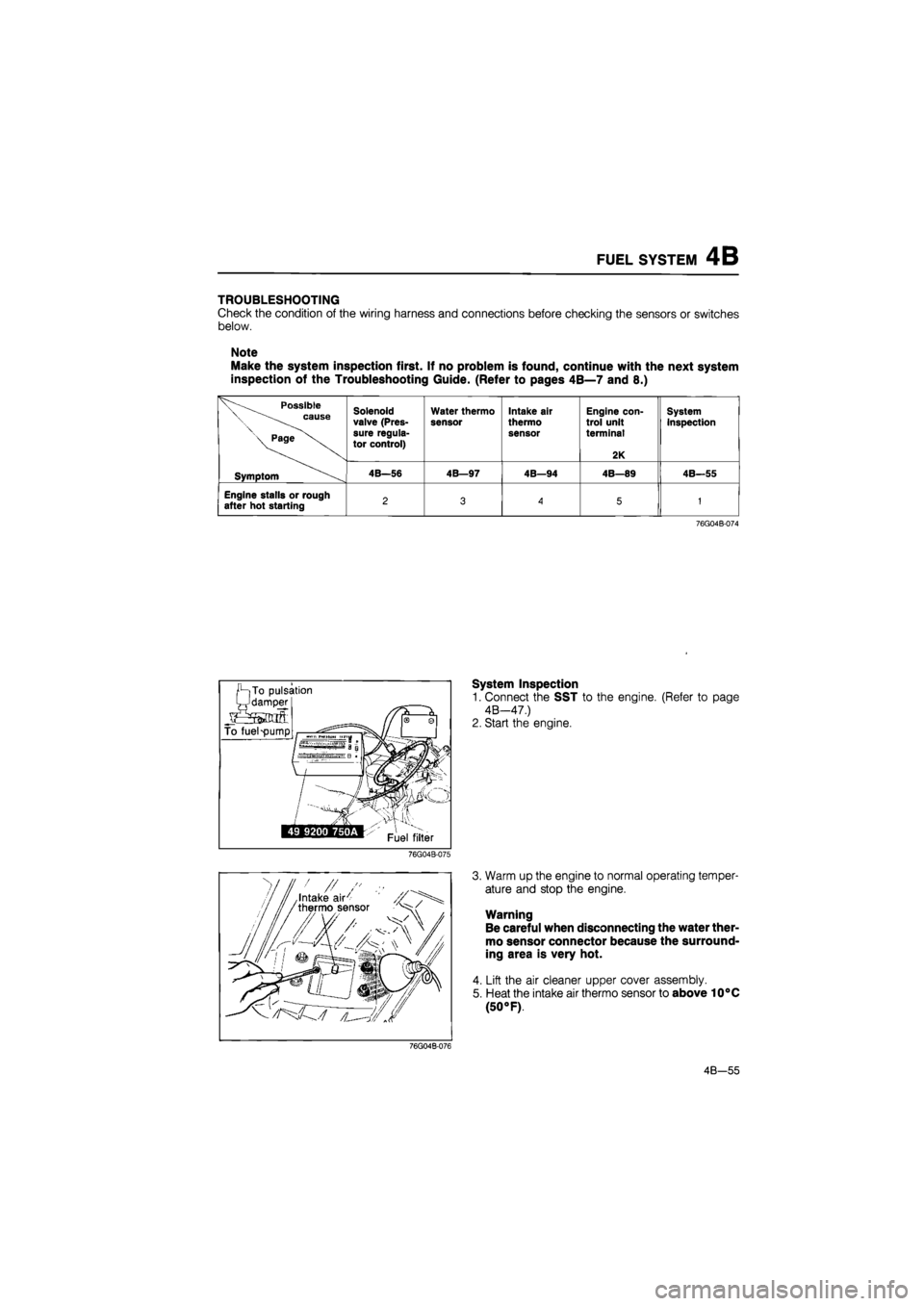
TROUBLESHOOTING
Check the condition of the wiring harness and connections before checking the sensors or switches
below.
Note
Make the system inspection first. If no problem is found, continue with the next system
inspection of the Troubleshooting Guide. (Refer to pages 4B—7 and 8.)
Possible \ cause
\ Page
Solenoid valve (Pres-sure regula-tor control)
Water thermo
sensor Intake air
thermo sensor
Engine con-trol unit terminal
2K
System inspection
Symptom 4B—56 4B—97 4B—94 4B—89 4B—55
Engine stalls or rough after hot starting 2 3
A
5 1
76G04B-074
System Inspection
1. Connect the SST to the engine. (Refer to page
4B—47.)
2. Start the engine.
76G04B-075
3. Warm up the engine to normal operating temper-
ature and stop the engine.
Warning
Be careful when disconnecting the water ther-
mo sensor connector because the surround-
ing area is very hot.
4. Lift the air cleaner upper cover assembly.
5. Heat the intake air thermo sensor to above 10°C
(50 °F).
76G04B-076
4B—55
Page 522 of 1865
4B FUEL SYSTEM
Pressure Regulator
1. Disconnect the vacuum hose and fuel return hose.
2. Remove the pressure regulator.
3. Install in the reverse order of removal.
Tightening torque:
8—11 N-m (0.8—1.1 m-kg, 69—95 in-lb)
76G04B-084
Pulsation Damper
1. Loosen the pulsation damper and remove it.
2. Install in the reverse order of removal.
76G04B-085
^-Fuel hose
ML*? ^-Fuel pump
^silntank filter
ti* e
76G04B-086
h
tS
Is o
Sjfbj
Fuel Filter
Low pressure side
Refer to page 4B—57.
86U04A-116
High pressure side
The fuel filter must be replaced at the intervals out-
lined in the maintenance schedule.
Warning
Always work away from sparks or open
flames.
1. Disconnect the fuel hoses from the fuel filter.
2. Remove the fuel filter and the bracket.
3. Install a new filter and the bracket.
4. Connect the fuel hoses.
Note
When installing the filter, push the fuel hoses
fully onto the fuel filter and secure the hoses
with spring clamps.
4B-60
Page 524 of 1865
4B FUEL SYSTEM
Inspection
1. Check the fuel tank for cracks and corrosion.
2. If any defect is found, repair or replace the tank.
Warning
Before repairing, clean the fuel tank thorough-
ly with steam to sufficiently remove all explo-
sive gas.
86U04A-118
Installation
Install in the reverse order of removal, referring to the installation note.
Torque Specifications
22—30 N-m (2.2—3.1 m-kg, 16—22 ft-lb)
4B—62
86U04A-119
Page 534 of 1865
4B EGR SYSTEM
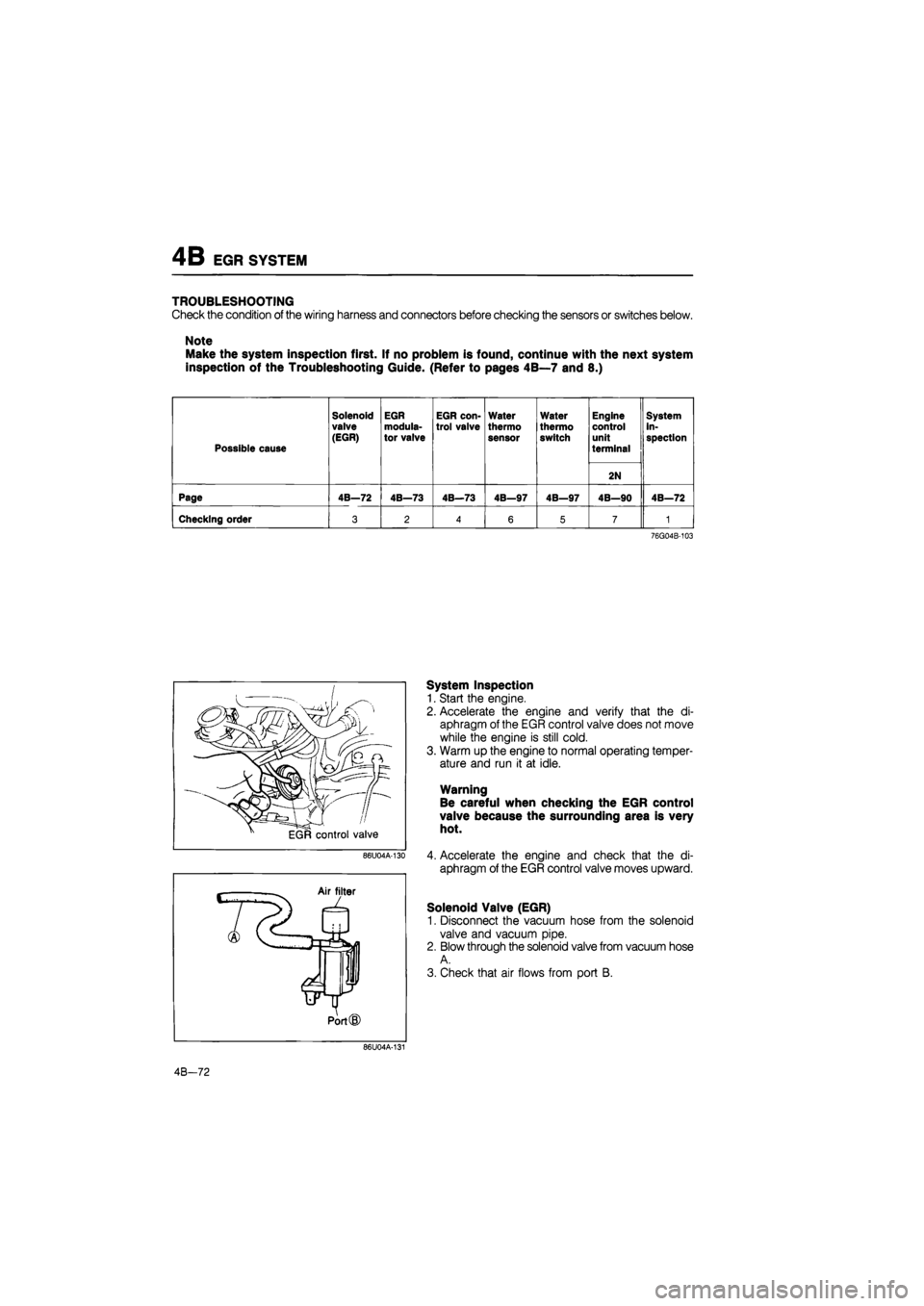
TROUBLESHOOTING
Check the condition of the wiring harness and connectors before checking the sensors or switches below.
Note
Make the system inspection first. If no problem is found, continue with the next system
inspection of the Troubleshooting Guide. (Refer to pages 4B—7 and 8.)
Possible cause
Solenoid
valve (EGR)
EGR modula-tor valve
EGR con-trol valve
Water
thermo sensor
Water
thermo switch
Engine control unit
terminal
System in-spection
2N
Page 4B—72 4B—73 4B—73 4B—97 4B—97 4B—90 4B—72
Checking order 3 2 4 6 5 7 1
76G04B-103
86U04A-130
System Inspection
1. Start the engine.
2. Accelerate the engine and verify that the di-
aphragm of the EGR control valve does not move
while the engine is still cold.
3. Warm up the engine to normal operating temper-
ature and run it at idle.
Warning
Be careful when checking the EGR control
valve because the surrounding area is very
hot.
4. Accelerate the engine and check that the di-
aphragm of the EGR control valve moves upward.
Solenoid Valve (EGR)
1. Disconnect the vacuum hose from the solenoid
valve and vacuum pipe.
2. Blow through the solenoid valve from vacuum hose
A.
3. Check that air flows from port B.
86U04A-131
4B-72
Page 574 of 1865
TROUBLESHOOTING WITH SST 4C
49 H018 9A1
negative battery cable
^ll
Test connector: (Green, 1 pin)
86U04A-015
Ignition switch:
ON
for six
seconds
76G04C-014
2. Connect the SST to the check connector.
3. Ground the test connector (Green, 1-pin) with a
jumper wire.
4. Turn the ignition switch ON for six seconds (do
not start the engine).
5. Start and warm up the engine, then run it at 2,000
rpm for two minutes.
6. Verify that no code numbers are displayed.
PRINCIPLE OF CODE CYCLE
Malfunction codes are determined as shown below
86U04A-017
1. Code cycle break
The time between warning code cycles is 4.0 sec (the time the light is off).
ON
OFF
1 cycle Malfunction code
cycle break
4.0 sec.
86U04A-018
4C—13
Page 615 of 1865
4C FUEL SYSTEM
f-|To pulsation
-'damper
76G04C-092
Pressure regulator
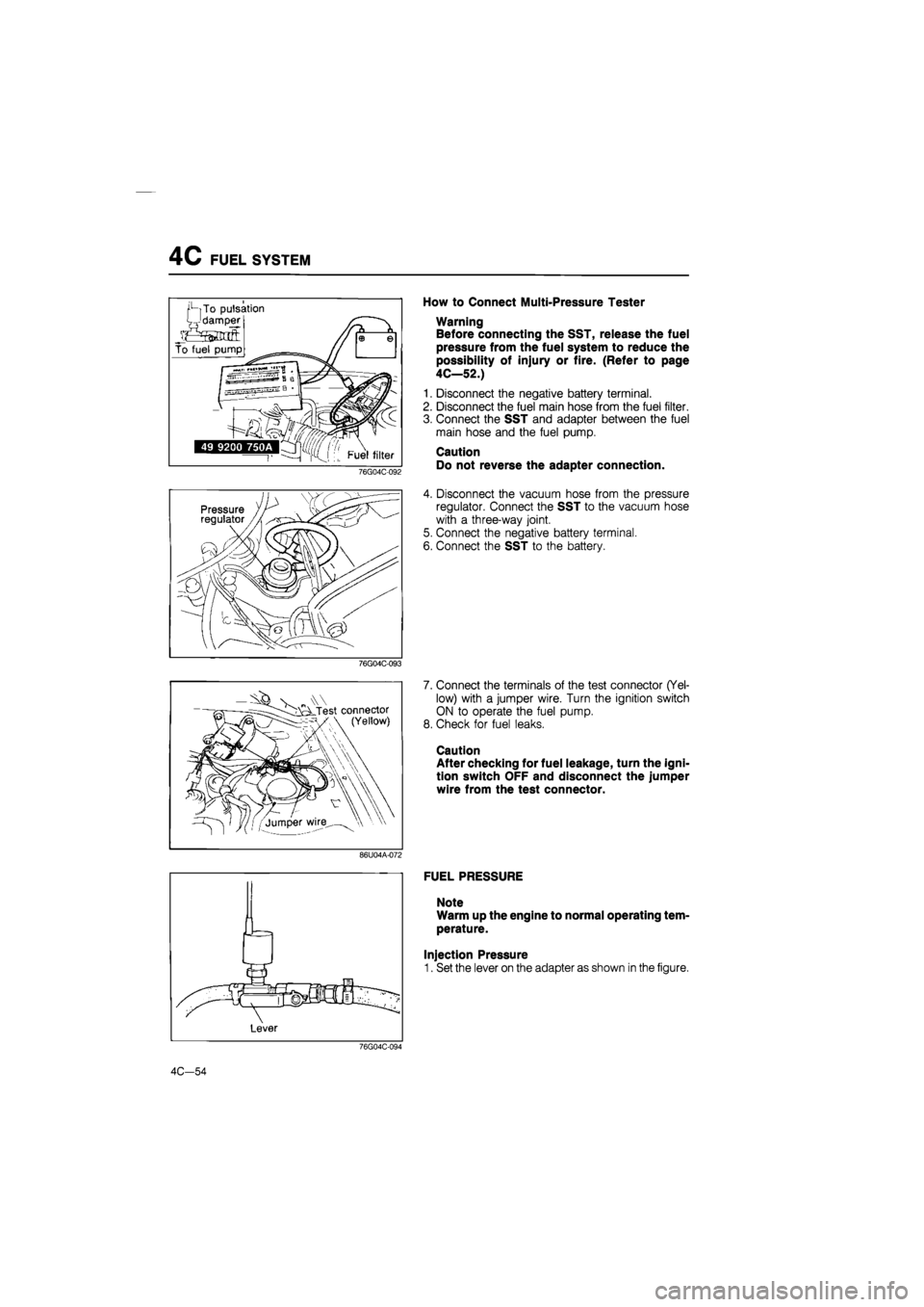
How to Connect Multi-Pressure Tester
Warning
Before connecting the SST, release the fuel
pressure from the fuel system to reduce the
possibility of injury or fire. (Refer to page
4C—52.)
1. Disconnect the negative battery terminal.
2. Disconnect the fuel main hose from the fuel filter.
3. Connect the SST and adapter between the fuel
main hose and the fuel pump.
Caution
Do not reverse the adapter connection.
4. Disconnect the vacuum hose from the pressure
regulator. Connect the SST to the vacuum hose
with a three-way joint.
5. Connect the negative battery terminal.
6. Connect the SST to the battery.
76G04C-093
V „ Test connector (Yellow)
7. Connect the terminals of the test connector (Yel-
low) with a jumper wire. Turn the ignition switch
ON to operate the fuel pump.
8. Check for fuel leaks.
Caution
After checking for fuel leakage, turn the igni-
tion switch OFF and disconnect the jumper
wire from the test connector.
86U04A-072
FUEL PRESSURE
Note
Warm up the engine to normal operating tem-
perature.
Injection Pressure
1. Set the lever on the adapter as shown in the figure.
76G04C-094
4C-54
Page 617 of 1865
4C FUEL SYSTEM
86U04A-078
76G04C-097
76G04C-098
„\W cLTest connector (Yellow)
'-/jumper wire \\ \ •
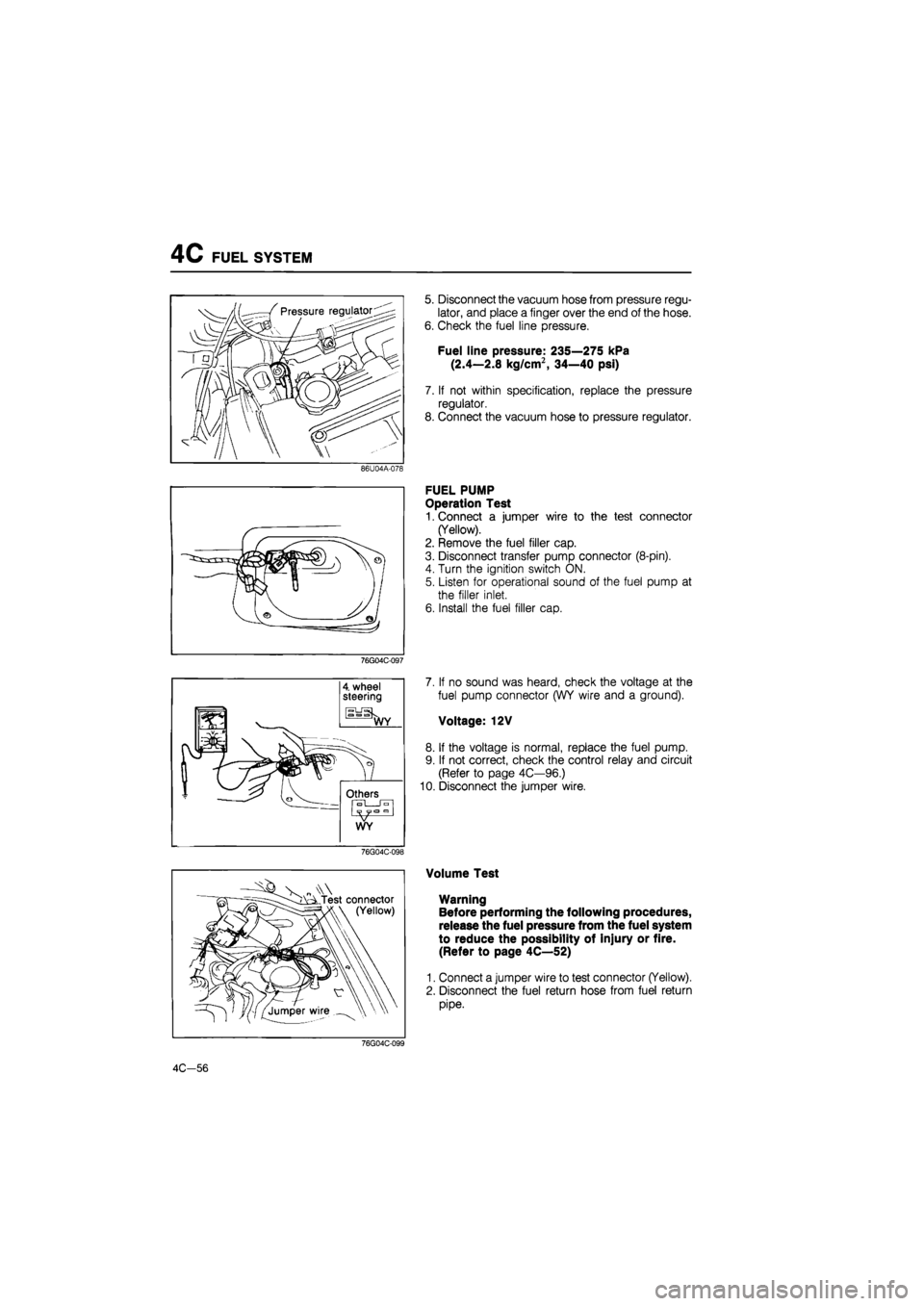
5. Disconnect the vacuum hose from pressure regu-
lator, and place a finger over the end of the hose.
6. Check the fuel line pressure.
Fuel line pressure: 235—275 kPa
(2.4—2.8 kg/cm2, 34—40 psi)
7. If not within specification, replace the pressure
regulator.
8. Connect the vacuum hose to pressure regulator.
FUEL PUMP
Operation Test
1. Connect a jumper wire to the test connector
(Yellow).
2. Remove the fuel filler cap.
3. Disconnect transfer pump connector (8-pin).
4. Turn the ignition switch ON.
5. Listen for operational sound of the fuel pump at
the filler inlet.
6. Install the fuel filler cap.
7. If no sound was heard, check the voltage at the
fuel pump connector (WY wire and a ground).
Voltage: 12V
8. If the voltage is normal, replace the fuel pump.
9. If not correct, check the control relay and circuit
(Refer to page 4C—96.)
10. Disconnect the jumper wire.
Volume Test
Warning
Before performing the following procedures,
release the fuel pressure from the fuel system
to reduce the possibility of injury or fire.
(Refer to page 4C—52)
1. Connect a jumper wire to test connector (Yellow).
2. Disconnect the fuel return hose from fuel return
pipe.
76G04C-099
4C-56
Page 619 of 1865
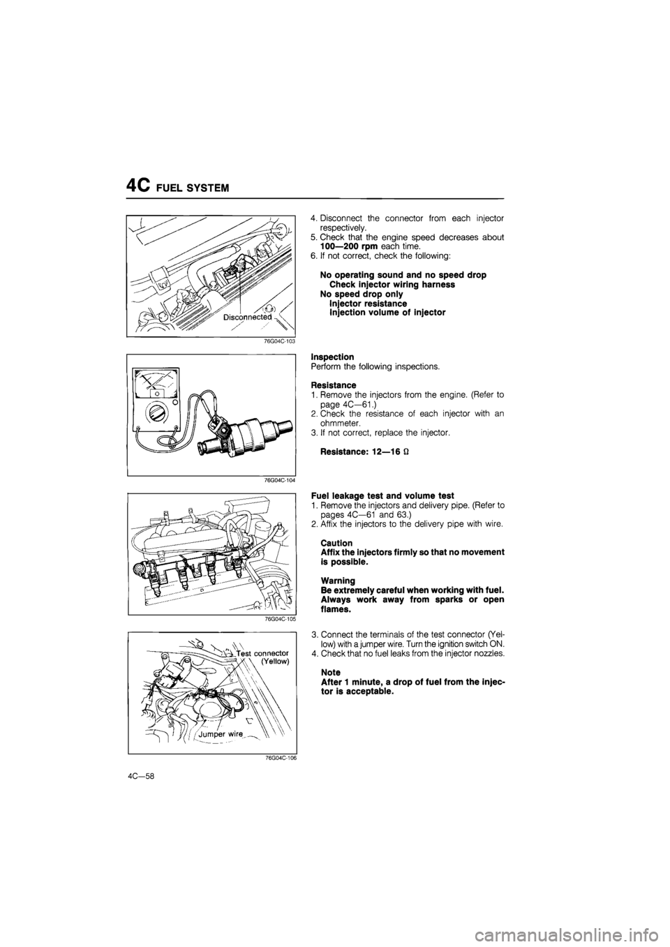
4C FUEL SYSTEM
76G04C-103
76G04C-104
76G04C-105
- s A Test connector I \ (Yellow)
4. Disconnect the connector from each injector
respectively.
5. Check that the engine speed decreases about
100—200 rpm each time.
6. If not correct, check the following:
No operating sound and no speed drop
Check injector wiring harness
No speed drop only
Injector resistance
Injection volume of injector
Inspection
Perform the following inspections.
Resistance
1. Remove the injectors from the engine. (Refer to
page 4C—61.)
2. Check the resistance of each injector with an
ohmmeter.
3. If not correct, replace the injector.
Resistance: 12—16 Q
Fuel leakage test and volume test
1. Remove the injectors and delivery pipe. (Refer to
pages 4C—61 and 63.)
2. Affix the injectors to the delivery pipe with wire.
Caution
Affix the injectors firmly so that no movement
is possible.
Warning
Be extremely careful when working with fuel.
Always work away from sparks or open
flames.
3. Connect the terminals of the test connector (Yel-
low) with a jumper wire. Turn the ignition switch ON.
4. Check that no fuel leaks from the injector nozzles.
Note
After 1 minute, a drop of fuel from the injec-
tor is acceptable.
76G04C-106
4C—58