Page 1164 of 1865
7C DISASSEMBLY
12. Remove the control rod.
(1) Remove the pin, and remove the control rod
from the transaxle.
Warning
Be careful when removing the control rod, the
detent ball will be pushed out by spring force.
(2) Remove the detent ball and spring.
76G07C-119
7C-50
Page 1289 of 1865

10
STEERING SYSTEM
OUTLINE 10— 2
STRUCTURAL VIEW 10— 2 SPECIFICATIONS 10— 6
TROUBLESHOOTING GUIDE 10— 7
MANUAL STEERING 10— 7
POWER STEERING 10— 8
4WS 10— 9
ON-VEHICLE MAINTENANCE 10— 10
STEERING WHEEL PLAY 10— 10
LOOSENESS OR PLAY OF THE
STEERING WHEEL 10— 10
STEERING WHEEL EFFORT 10— 10
POWER STEERING FLUID LEVEL 1 fl-11
LOOSE OR DAMAGED
OIL PUMP BELT IC— 12
REAR STEERING GEAR OIL 10— 12 LEAKAGE OF POWER STEERING
FLUID 10— 13
INSPECTION AND ADJUSTMENT. 10— 15
BLEEDING OF POWER STEERING
SYSTEM 10— 15
POWER STEERING PRESSURE ... 10— 16
TIE-ROD END BOOTS 10— 18
REMOVAL AND INSTALLATION .. 10— 18
STEERING WHEEL AND COLUMN 10— 21
STRUCTURAL VIEW 10— 21
REMOVAL 10— 22
DISASSEMBLY AND ASSEMBLY.. 10— 24
INSPECTION 10— 25
INSTALLATION 1 fl-27
STEERING GEAR AND LINKAGE .. IC— 28
STRUCTURAL VIEW 10— 28
REMOVAL 10— 29
INSTALLATION 10— 30
4-WHEEL STEERING GEAR AND
LINKAGE 10— 31
STRUCTURAL VIEW 10— 31 4WS PERFORMANCE INSPECTION 10— 32
ADJUSTMENT OF STEERING
ANGLE TRASFER SHAFT 10— 35
REMOVAL AND INSTALLATION .. 10— 37
INSPECTION 10— 44
MANUAL STEERING 10— 48
DISASSEMBLY 10— 48
INSPECTION 10— 51
ASSEMBLY 10— 52
ENGINE SPEED SENSING POWER
STEERING 10— 58
DISASSEMBLY 10— 58
INSPECTION 10— 62
ASSEMBLY 10— 64
ELECTRONICALLY-CONTROLLED
POWER STEERING 10— 75
DISASSEMBLY 10— 75
INSPECTION 10— 78
ASSEMBLY 10— 79
OIL PUMP 10— 83
REMOVAL AND INSTALLATION .. 10— 83
ELECTRICAL COMPONENTS OF
ELECTRONICALLY-CONTROLLED
POWER STEERING 10— 87
CIRCUIT DIAGRAM 10— 87
TROUBLESHOOTING GUIDE 10— 87
TROUBLESHOOTING 10— 87
ELECTRICAL COMPONENTS OF
4 WHEEL STEERING 10— 94
CIRCUIT DIAGRAM 10— 94
TROUBLESHOOTING GUIDE 10— 95
TROUBLESHOOTING 10— 95
4WS WARNING LIGHT 10—102
SPEED SENSOR (IN METER) 10—103
SPEED SENSOR (AT TRANSAXLE) 10—103
REAR-TO-FRONT STEERING
RATIO SENSOR 10—103
OIL LEVEL SWITCH
(IN P/S RESERVOIR) 10—103
RELAY AND TIMER 10—104 76G10X-001
Page 1304 of 1865
![MAZDA 626 1987 Workshop Manual
1 0 INSPECTION AND ADJUSTMENT
86U10X023
2WS
To oil pump
Si£r To gear housing
86U10X-024
86U10X-025
Thermometer [50—60°C (122—140°C)]
ii ^
Gauge
Close valve
completely
POWER STEERIN MAZDA 626 1987 Workshop Manual
1 0 INSPECTION AND ADJUSTMENT
86U10X023
2WS
To oil pump
Si£r To gear housing
86U10X-024
86U10X-025
Thermometer [50—60°C (122—140°C)]
ii ^
Gauge
Close valve
completely
POWER STEERIN](/manual-img/28/57059/w960_57059-1303.png)
1 0 INSPECTION AND ADJUSTMENT
86U10X023
2WS
To oil pump
Si£r To gear housing
86U10X-024
86U10X-025
Thermometer [50—60°C (122—140°C)]
ii ^
Gauge
Close valve
completely
POWER STEERING PRESSURE
1. Disconnect the high-pressure hose of the gear
housing side, and attach the SST.
Tightening torque:
39—49 N-m (4.0—5.0 m-kg, 29—36 ft-lb)
2. Bleed air from the system.
3. Open the gauge valve fully, then start the engine
and turn the steering wheel fully left and right to
raise the fluid temperature to 50—60°C
(122—140°F)
4. To measure the fluid pressure generated by the
oil pump, close the gauge valve completely and
increase the engine speed to 1,000—1,500 rpm.
If the fluid pressure is low, replace the oil pump
assembly.
Warning
If the valve is left closed for more than 15 sec-
onds, the fluid temperature will increase ex-
cessively and adversely affect the oil pump.
Oil pump fluid pressure
2WS
7,355—7,846 kPa
(75—80 kg/cm2, 1,066—1,138 psi)
4WS
Front 8,093—8,829 kPa
(82.5—90.0 kg/cm2, 1,173—1,280 psi)
Rear 7,112—7,848 kPa
(72.5—80.0 kg/cm2, 1,031—1,138 psi)
To measure the fluid pressure generated at the
gear housing, first open the gauge valve complete-
ly, increase the engine speed to 1,000—1,500
rpm, and then turn the steering wheel fully to the
left and right.
Warning
If the steering wheel is kept in the fully turned
position for more than 15 seconds, the fluid
temperature will rise excessively.
80U10X-026
10—16
Page 1322 of 1865
1 0 4-WHEEL STEERING GEAR AND LINKAGE
(Example) ^"in)
-I
8 mm (0.31 in)
1 1111111
- ^Center
10 mm (0.39 in)
86U10X-309
(8) The center position can be determined from
the left/right measurements in (5) and (7) above.
Example:
Right rotation.... 10 mm (0.39 in)
Left rotation....8 mm (0.31 in)
Center = Right 1 mm (0.04 in)
(9) Check that the center is within specification.
Specification
= R 5 mm (0.4 in ) to L 5 mm (0.4 in)
(10) If not correct, adjust the steering angle trans-
fer shaft.
2. Steering Inspection
With the vehicle stopped and the engine running,
check that the rear wheels turn in the opposite
direction when the steering wheel is turned and that
there is no abnormal noise.
86U10X-310
3.4WS Electric System Inspection
Drive the vehicle and check that the 4WS warning
light does not come on at over 40 km/h (25mph).
86U10X-311
10—34
Page 1323 of 1865

4-WHEEL STEERING GEAR AND LINKAGE 1 0
Front joint Rear joint
Rear bracket
Front bracket
76G10X-033
86U10X-313
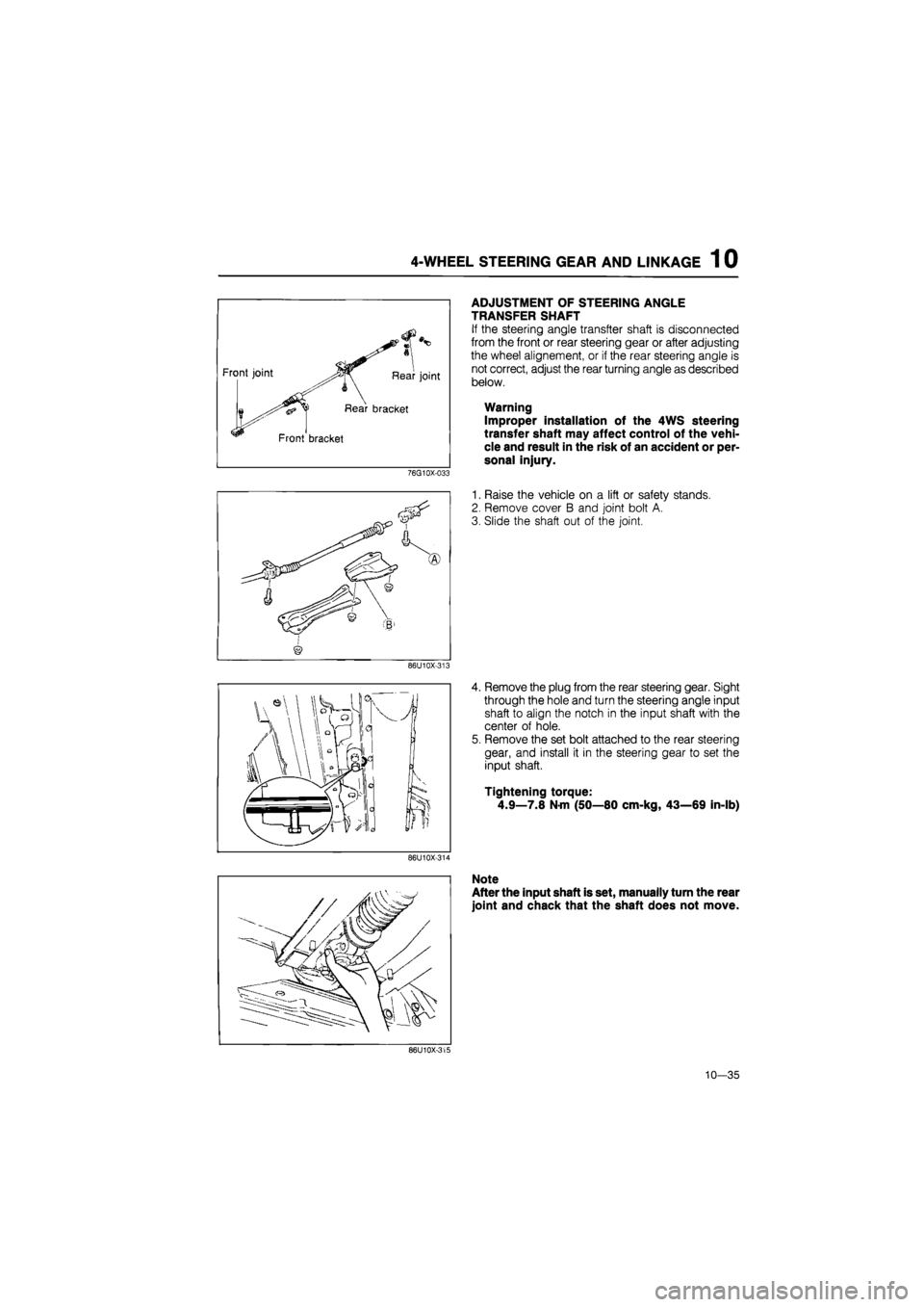
ADJUSTMENT OF STEERING ANGLE
TRANSFER SHAFT
If the steering angle transfter shaft is disconnected
from the front or rear steering gear or after adjusting
the wheel alignement, or if the rear steering angle is
not correct, adjust the rear turning angle as described
below.
Warning
Improper installation of the 4WS steering
transfer shaft may affect control of the vehi-
cle and result in the risk of an accident or per-
sonal injury.
1. Raise the vehicle on a lift or safety stands.
2. Remove cover B and joint bolt A.
3. Slide the shaft out of the joint.
4. Remove the plug from the rear steering gear. Sight
through the hole and turn the steering angle input
shaft to align the notch in the input shaft with the
center of hole.
5. Remove the set bolt attached to the rear steering
gear, and install it in the steering gear to set the
input shaft.
Tightening torque:
4.9—7.8 N-m (50—80 cm-kg, 43—69 in-lb)
86U10X-314
Note
After the input shaft is set, manually turn the rear
joint and chack that the shaft does not move.
86U10X-315
10—35
Page 1376 of 1865

1 0 ELECTRICAL COMPONENTS OF ELECTRONICALLY-CONTROLLED POWER STEERING (ECPS)
76G10X-020
76G10X-021
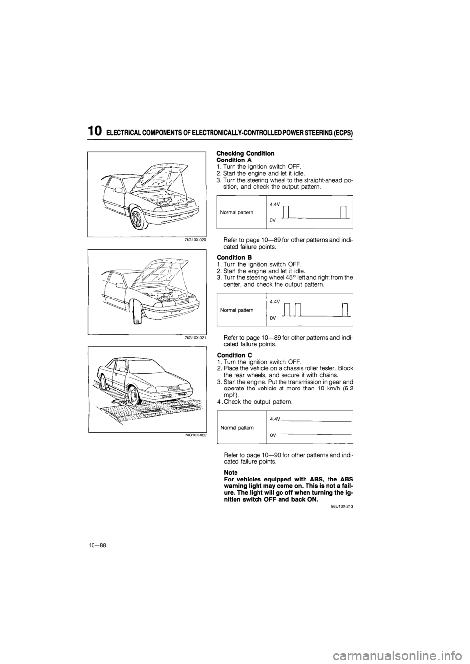
Checking Condition
Condition A
1. Turn the ignition switch OFF.
2. Start the engine and let it idle.
3. Turn the steering wheel to the straight-ahead po-
sition, and check the output pattern.
Refer to page 10—89 for other patterns and indi-
cated failure points.
Condition B
1. Turn the ignition switch OFF.
2. Start the engine and let it idle.
3. Turn the steering wheel 45° left and right from the
center, and check the output pattern.
Refer to page 10—89 for other patterns and indi-
cated failure points.
Condition C
1. Turn the ignition switch OFF.
2. Place the vehicle on a chassis roller tester. Block
the rear wheels, and secure it with chains.
3. Start the engine. Put the transmission in gear and
operate the vehicle at more than 10 km/h (6.2
mph).
4.Check the output pattern.
76G10X-022
Normal pattern
4 4V
Normal pattern Normal pattern
uV
Refer to page 10—90 for other patterns and indi-
cated failure points.
Note
For vehicles equipped with ABS, the ABS
warning light may come on. This is not a fail-
ure. The light will go off when turning the ig-
nition switch OFF and back ON.
86U10X-213
10—88
Page 1383 of 1865
ELECTRICAL COMPONENTS OF 4-WHEEL STEERING 1 0
TROUBLESHOOTING GUIDE
Self-Diagnosis Function
The four-wheel steering (4WS) control unit contains a self-diagnosis function to detect malfunctions
within itself, the 4WS electrical components and circuits.
If a malfunction is detected, the control unit indicates where the problem is located and the 4WS warn-
ing light in the instrument cluster will flash for one minute with a specific pattern,
Troubleshoot the 4WS system according to the following flow chart.
Symptom of problem
76G10X-026
TROUBLESHOOTING
Checking Condition
Condition A
1. Turn the ignition switch OFF.
2. Start the engine after the ignition switch has been
OFF for at least 10 seconds, and check if the 4WS
warning light flashes or illuminates within 60
seconds.
3.
If
flashing or illumination occurs, inspect the circuit.
(Refer to page 10—95.)
76G10X-027
10—95
Page 1384 of 1865
1 0 ELECTRICAL COMPONENTS OF 4-WHEEL STEERING
Condition B
1. Place the vehicle on a chassis roller tester. Block
the rear wheels, and secure it with chains.
2. Turn the ignition switch OFF.
3. Start the engine after the ignition switch has been
OFF for at least 10 seconds. Put the transmission
in gear and operate the vehicle at more than 40
km/h (25 mph).
4. Check if the 4WS warning light flashes or il-
luminates within 60 seconds.
5.
If
flashing or illumination occurs, inspect the circuit
by referring to the table below.
76G10X045
Diagnosis Output Pattern
Warning light output pattern
0.5 sec —i 2.5 sec
Malfunction
Normal operation, control unit or wir-ing harness
Speed sensors or
wiring harness
Flow chart
No.
4WS—0
4WS—1
Rear steering gear
assembly
Solenoid valve or wiring harness
Stepper motor or wiring harness
Rear-to-front steer-ing ratio sensor or wiring harness
4WS—2
4WS—3
4WS—4
4WS—5
86U10X-225
10-96