Page 1385 of 1865
ELECTRICAL COMPONENTS OF 4-WHEEL STEERING 1 0
Warning light output pattern Malfunction Flow chart No.
ON
ncc
Stepper motor or wiring harness 4WS—6 Stepper motor or wiring harness 4WS—6
ON
r\cc
Oil leakage or oil
level switch
4WS—7 Oil leakage or oil
level switch
4WS—7
ON
OFF
Control unit 4WS—8 Control unit 4WS—8
ON
ncc
Control unit, alter-nator, or wiring harness
4WS—9
ON
ncc
Control unit, alter-nator, or wiring harness
4WS—9 Control unit, alter-nator, or wiring harness
4WS—9
86U10X-226
10—97
Page 1386 of 1865
1 0 ELECTRICAL COMPONENTS OF 4-WHEEL STEERING
4WS-0 Normal operation or failure of con-trol unit or harness
Start engine.
Disconnect R-01 (7-pin) connector. Check that 4WS warning light flashes or illuminates.
NG
Repair harness. (Fuse box to Control unit or Control unit to Body ground).
YES No electrical problem.
NO
Reconnect connector.
Check voltage between terminals and body ground.
Terminal Voltage
G(B) OV
H(B) OV
K(G) Approx. 12V
L(G) Approx. 12V
N(B) OV
OK Replace control unit.
4WS-1 Failure of speed sensors or wiring
harness
Check speed sensor at transaxle. (Referring to page 10—103)
OK
NG Replace speed sensor.
Check for continuity between terminal of transaxle speed sensor and R (O) terminal of the control unit connector.
NG^ Repair wiring harness (Control unit to Transaxle
speed sensor).
Cont'd 76G10X-028
10—98
Page 1390 of 1865
1 0 ELECTRICAL COMPONENTS OF 4-WHEEL STEERING
flashes
Replace control unit
4WS-9 Failure of control unit, alternator, or wiring harness
Start engine,
I
Check voltage between terminal of control unit con-nector and body ground.
Terminal Voltage
G(B) OV
H (B) OV
K(G) Approx. 12V
L (G) Approx. 12V
N(B) OV
OK
NG
Check 4WS relay and timer (Refer to page 10—103) -
OK
Check battery, harness, and alternator.
NG
Turn ignition switch OFF. Start engine. Check if 4WS warning light flashes or illuminates.
NO
Momentary problem (If warning light often flashes or illuminates, check battery and alter-nator. Replace control unit if necessary).
YES
Replace control unit.
Replace relay and timer
76G10X-031
4WS WARNING LIGHT
1. Turn the ignition switch OFF.
2. Turn the ignition switch ON, and check that the
4WS warning light illuminates.
3. If there is no illumination, check the warning light
bulb and wiring harness.
Replace the control unit if necessary.
86U10X-232
10-102
Page 1393 of 1865

11
BRAKING SYSTEM
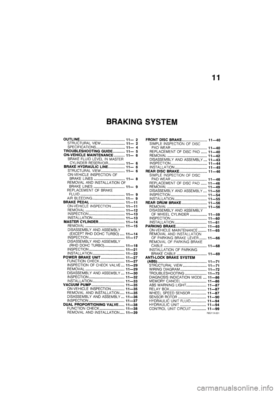
OUTLINE 11—2
STRUCTURAL VIEW 11—2
SPECIFICATIONS 11— 4
TROUBLESHOOTING GUIDE 11— 5
ON-VEHICLE MAINTENANCE 11—6
BRAKE FLUID LEVEL IN MASTER
CYLINDER RESERVOIR 11— 6
BRAKE HYDRAULIC LINE 11—6
STRUCTURAL VIEW 11—6
ON-VEHICLE INSPECTION OF
BRAKE LINES 11— 8
REMOVAL AND INSTALLATION OF
BRAKE LINES 11— 9
REPLACEMENT OF BRAKE
FLUID 11— 9
AIR BLEEDING 11— 9
BRAKE PEDAL 11—11
ON-VEHICLE INSPECTION 11—11
REMOVAL 11—12
INSPECTION 11—13
INSTALLATION 11—13
MASTER CYLINDER 11—14
REMOVAL 11—15
DISASSEMBLY AND ASSEMBLY
(EXCEPT RHD DOHC TURBO).... 11—14
INSPECTION 11—17
DISASSEMBLY AND ASSEMBLY
(RHD DOHC TURBO) 11—18
INSPECTION 11—21
INSTALLATION 11—22
POWER BRAKE UNIT 11—27
FUNCTION CHECK 11—27
INSPECTION OF CHECK VALVE... 11—29
REMOVAL 11—29
DISASSEMBLY AND ASSEMBLY... 11—30
INSPECTION 11—32
INSTALLATION 11—33
VACUUM PUMP 11—35
ON-VEHICLE INSPECTION 11—35
REMOVAL AND INSTALLATION.... 11—35
DISASSEMBLY AND ASSEMBLY... 11—36
INSPECTION 11—37
DUAL PROPORTIONING VALVE 11—38
FUNCTION CHECK 11—38
REMOVAL AND INSTALLATION.... 11—39
FRONT DISC BRAKE 11—40
SIMPLE INSPECTION OF DISC
PAD WEAR 11—40
REPLACEMENT OF DISC PAD 11—40
REMOVAL 11—42
DISASSEMBLY AND ASSEMBLY... 11—43
INSPECTION 11—44
INSTALLATION 11—45
REAR DISC BRAKE 11—46
SIMPLE INSPECTION OF DISC
PAD WEAR 11—46
REPLACEMENT OF DISC PAD 11—46
REMOVAL 11—49
DISASSEMBLY AND ASSEMBLY... 11—50
INSPECTION 11—54
INSTALLATION 11—55
REAR DRUM BRAKE 11—56
REMOVAL 11—56
DISASSEMBLY AND ASSEMBLY
OF WHEEL CYLINDER 11—59
INSPECTION 11—60
INSTALLATION 11—61
PARKING BRAKE 11—65
ON-VEHICLE MAINTENANCE 11—65
REMOVAL AND INSTALLATION
OF PARKING BRAKE LEVER 11—66
REMOVAL OF PARKING BRAKE
CABLE 11—68
INSTALLATION OF PARKING
BRAKE CABLE 11—69
ANTI-LOCK BRAKE SYSTEM
(ABS) 11—71
STRUCTURAL VIEW 11—71
WIRING DIAGRAM 11—72
TROUBLESHOOTING 11—73
DIAGNOSIS INDICATION MODE ... 11—86
MEMORY CANCEL 11—86
ABS WARNING LIGHT 11—87
RELAY BOX 11—87
WHEEL SPEED SENSOR 11—87
SENSOR ROTOR 11—90
HYDRAULIC UNIT FLUID 11—94
HYDRAULIC UNIT 11—94
CONTROL UNIT CIRCUIT 11—99
76G11X-001
Page 1432 of 1865

1 1 FRONT DISC BRAKE
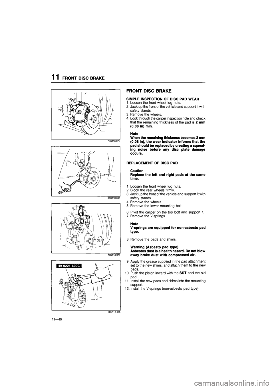
76G11X-073
86U11X066
76G11X-074
FRONT DISC BRAKE
SIMPLE INSPECTION OF DISC PAD WEAR
1. Loosen the front wheel lug nuts.
2. Jack up the front of the vehicle and support it with
safety stands.
3. Remove the wheels.
4. Look through the caliper inspection hole and check
that the remaining thickness of the pad is 2 mm
(0.08 in) min.
Note
When the remaining thickness becomes 2 mm
(0.08 in), the wear indicator informs that the
pad should be replaced by creating a squeal-
ing noise before any disc plate damage
occurs.
REPLACEMENT OF DISC PAD
Caution
Replace the left and right pads at the same
time.
1. Loosen the front wheel lug nuts.
2. Block the rear wheels firmly.
3. Jack up the front of the vehicle and support it with
safety stands.
4. Remove the wheels.
5. Remove the lower mounting bolt.
6. Pivot the caliper on the top bolt and support it.
7. Remove the V-springs.
Note
V-springs are equipped for non-asbesto pad
type.
8. Remove the pads and shims.
Warning (Asbesto pad type)
Asbestos dust is a health hazard. Do not blow
away brake dust with compressed air.
9. Apply the grease supplied in the pad attachment
set to the new shims, and attach them to the new
pads.
10. Push the piston inward with the SST and the old
pad.
11. Install the new pads and shims into the mounting
support.
12. Install the V-springs (non-asbesto pad type).
76G11X-075
11-40
Page 1434 of 1865
1 1 FRONT DISC BRAKE
REMOVAL
1. Loosen the wheel lug nuts.
2. Jack up the front of the vehicle and support it with safety stands.
3. Remove the wheels.
4. Remove in the sequence shown in the figure.
Warning Asbestos dust is a health hazard. Do not blow away brake dust with compressed air.
Caution
Brake fluid will damage painted surfaces. If it does get on a painted surface, wipe it off
immediately.
76G11X-078
1. Flexible hose
2. Caliper assembly
3. V-spring
4. Outer pad and shim
5. Inner pad and shim
6. Guide plate
7. Mounting support
8. Disc plate (Refer to section 9)
11—42
Page 1439 of 1865

REAR DISC BRAKE 1 1
REAR DISC BRAKE
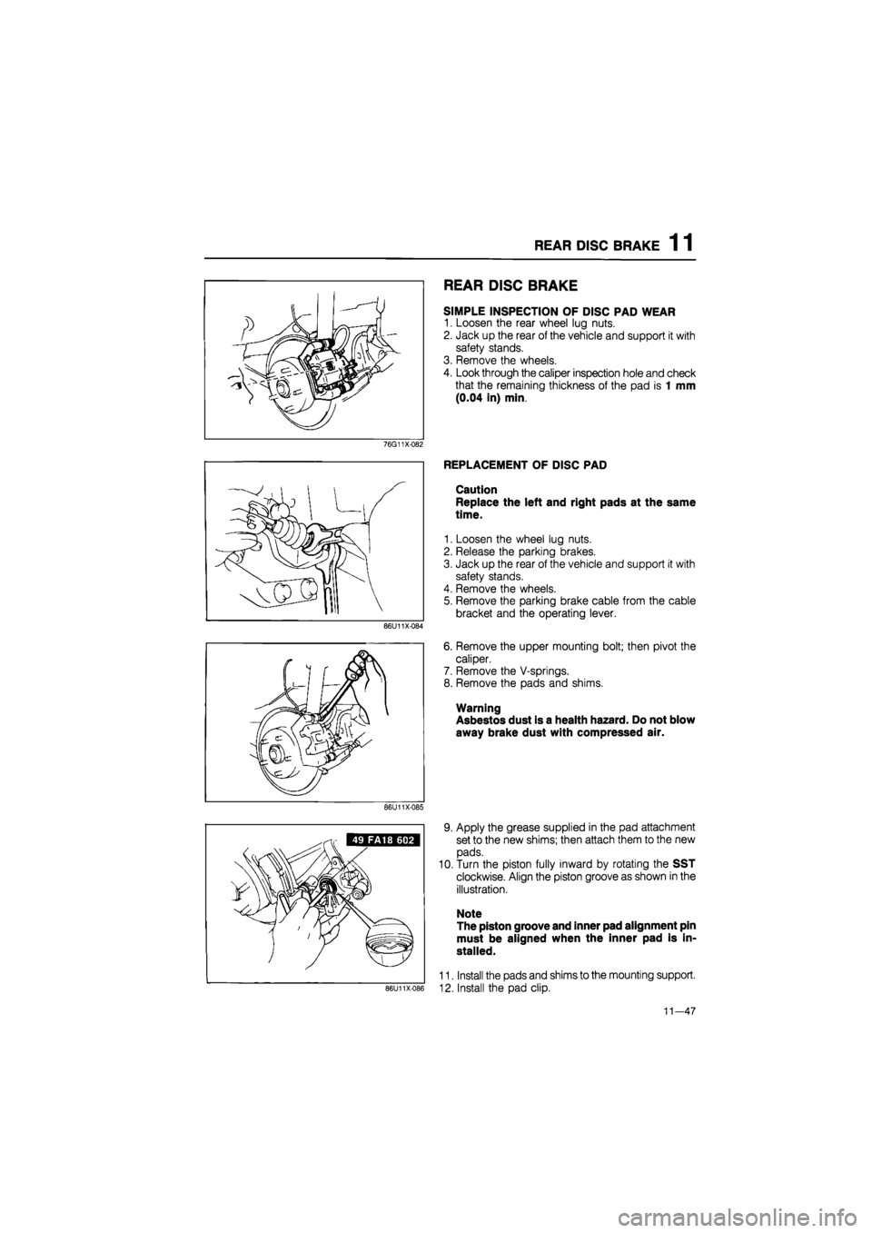
SIMPLE INSPECTION OF DISC PAD WEAR
1. Loosen the rear wheel lug nuts.
2. Jack up the rear of the vehicle and support it with
safety stands.
3. Remove the wheels.
4. Look through the caliper inspection hole and check
that the remaining thickness of the pad is 1 mm
(0.04 in) min.
76G11X-082
86U11X-084
REPLACEMENT OF DISC PAD
Caution
Replace the left and right pads at the same
time.
1. Loosen the wheel lug nuts.
2. Release the parking brakes.
3. Jack up the rear of the vehicle and support it with
safety stands.
4. Remove the wheels.
5. Remove the parking brake cable from the cable
bracket and the operating lever.
6. Remove the upper mounting bolt; then pivot the
caliper.
7. Remove the V-springs.
8. Remove the pads and shims.
Warning
Asbestos dust is a health hazard. Do not blow
away brake dust with compressed air.
86U11X-085
86U11X-086
9. Apply the grease supplied in the pad attachment
set to the new shims; then attach them to the new
pads.
10. Turn the piston fully inward by rotating the SST
clockwise. Align the piston groove as shown in the
illustration.
Note
The piston groove and inner pad alignment pin
must be aligned when the inner pad is in-
stalled.
11. Install the pads and shims to the mounting support.
12. Install the pad clip.
11—47
Page 1441 of 1865
REAR DISC BRAKE 1 1
REMOVAL
1. Loosen the wheel lug nuts.
2. Release the parking brakes.
3. Jack up the rear of the vehicle and support it with safety stands.
4. Remove the wheels.
5. Remove in the sequence shown in the figure.
Warning Asbestos dust is a health hazard. Do not blow away brake dust with compressed air.
Caution
Brake fluid will damage painted surfaces. If it does get on a painted surface, wipe it off
immediately.
76G11X-084
1. Parking brake cable
2. Flexible hose
3. Caliper assembly
4. V-spring
5. Pad and shim
6. Guide plate
7. Mounting support
8. Disc plate
(Refer to section 9)
11—49