Page 1404 of 1865
1 1 BRAKE PEDAL
Pedal-to-floor clearance
76G11X-009
REMOVAL
Remove in the sequence shown in the figure.
Pedal-to-Floor Clearance
Inspection
Check that the distance from the floor panel to the
center of the upper surface of the pedal pad is as
specified when the pedal is depressed with a force
of 589 N (60 kg, 132.3 lb).
Pedal-to-floor clearance:
LHD and RHD
95 mm (3.7 in) min.
If the distance is less than specified, check for the
following problems.
1. Air in brake system
2. Malfunction of automatic adjuster (rear drum
brakes)
3. Worn shoes or pads
86U11X-020
1. Clevis pin
2. Brake pedal
3. Return spring
4. Guide pipe
5. Bushing
6. Brake pad
11—12
Page 1432 of 1865

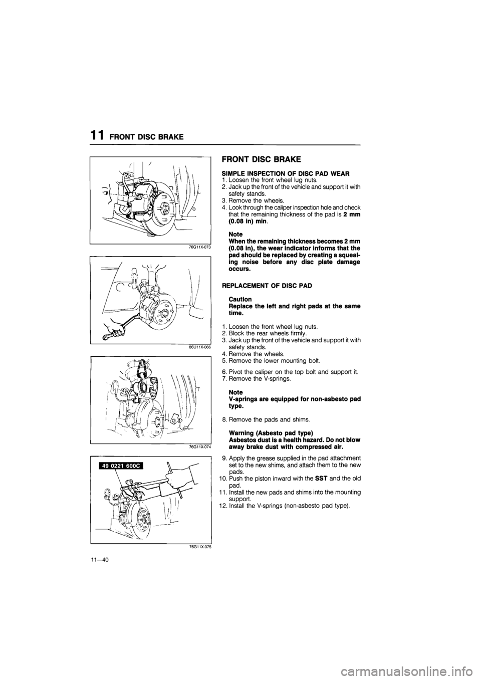
1 1 FRONT DISC BRAKE
76G11X-073
86U11X066
76G11X-074
FRONT DISC BRAKE
SIMPLE INSPECTION OF DISC PAD WEAR
1. Loosen the front wheel lug nuts.
2. Jack up the front of the vehicle and support it with
safety stands.
3. Remove the wheels.
4. Look through the caliper inspection hole and check
that the remaining thickness of the pad is 2 mm
(0.08 in) min.
Note
When the remaining thickness becomes 2 mm
(0.08 in), the wear indicator informs that the
pad should be replaced by creating a squeal-
ing noise before any disc plate damage
occurs.
REPLACEMENT OF DISC PAD
Caution
Replace the left and right pads at the same
time.
1. Loosen the front wheel lug nuts.
2. Block the rear wheels firmly.
3. Jack up the front of the vehicle and support it with
safety stands.
4. Remove the wheels.
5. Remove the lower mounting bolt.
6. Pivot the caliper on the top bolt and support it.
7. Remove the V-springs.
Note
V-springs are equipped for non-asbesto pad
type.
8. Remove the pads and shims.
Warning (Asbesto pad type)
Asbestos dust is a health hazard. Do not blow
away brake dust with compressed air.
9. Apply the grease supplied in the pad attachment
set to the new shims, and attach them to the new
pads.
10. Push the piston inward with the SST and the old
pad.
11. Install the new pads and shims into the mounting
support.
12. Install the V-springs (non-asbesto pad type).
76G11X-075
11-40
Page 1439 of 1865

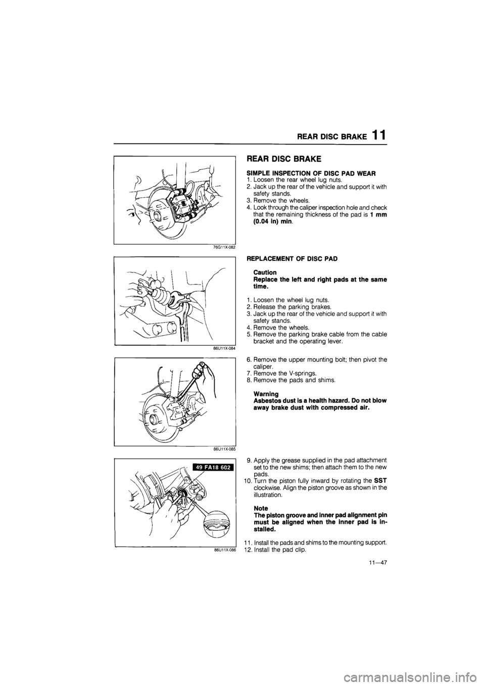
REAR DISC BRAKE 1 1
REAR DISC BRAKE
SIMPLE INSPECTION OF DISC PAD WEAR
1. Loosen the rear wheel lug nuts.
2. Jack up the rear of the vehicle and support it with
safety stands.
3. Remove the wheels.
4. Look through the caliper inspection hole and check
that the remaining thickness of the pad is 1 mm
(0.04 in) min.
76G11X-082
86U11X-084
REPLACEMENT OF DISC PAD
Caution
Replace the left and right pads at the same
time.
1. Loosen the wheel lug nuts.
2. Release the parking brakes.
3. Jack up the rear of the vehicle and support it with
safety stands.
4. Remove the wheels.
5. Remove the parking brake cable from the cable
bracket and the operating lever.
6. Remove the upper mounting bolt; then pivot the
caliper.
7. Remove the V-springs.
8. Remove the pads and shims.
Warning
Asbestos dust is a health hazard. Do not blow
away brake dust with compressed air.
86U11X-085
86U11X-086
9. Apply the grease supplied in the pad attachment
set to the new shims; then attach them to the new
pads.
10. Turn the piston fully inward by rotating the SST
clockwise. Align the piston groove as shown in the
illustration.
Note
The piston groove and inner pad alignment pin
must be aligned when the inner pad is in-
stalled.
11. Install the pads and shims to the mounting support.
12. Install the pad clip.
11—47