1987 MAZDA 626 coolant reservoir
[x] Cancel search: coolant reservoirPage 14 of 1865

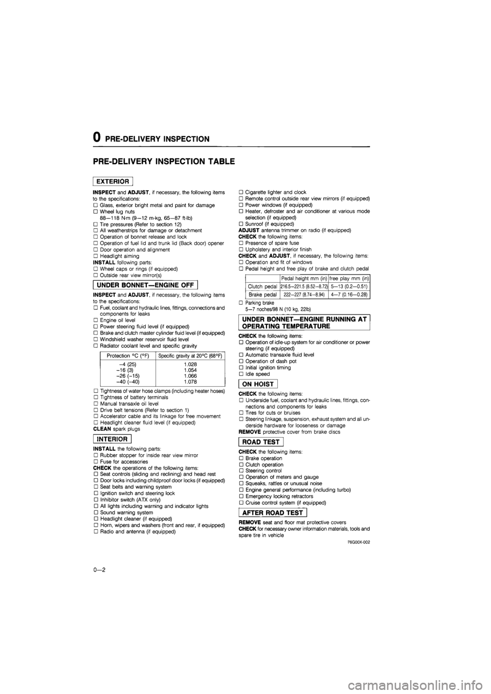
0 PRE-DELIVERY INSPECTION
PRE-DELIVERY INSPECTION TABLE
EXTERIOR
INSPECT and ADJUST, if necessary, the following items
to the specifications:
• Glass, exterior bright metal and paint for damage
• Wheel lug nuts
88—118 N m (9—12 m-kg, 65—87 ft-lb)
• Tire pressures (Refer to section 12)
• All weatherstrips for damage or detachment
• Operation of bonnet release and lock
• Operation of fuel lid and trunk lid (Back door) opener
• Door operation and alignment
• Headlight aiming
INSTALL following parts:
• Wheel caps or rings (if equipped)
• Outside rear view mirror(s)
UNDER BONNET—ENGINE OFF
INSPECT and ADJUST, if necessary, the following items
to the specifications:
• Fuel, coolant and hydraulic lines, fittings, connections and
components for leaks
• Engine oil level
• Power steering fluid level (if equipped)
• Brake and clutch master cylinder fluid level (if equipped)
• Windshield washer reservoir fluid level
• Radiator coolant level and specific gravity
Protection °C (°F) Specific gravity at 20°C (68°F)
-4 (25) 1.028
-16(3) 1.054
-26 (-15) 1.066 -40 (-40) 1.078
• Tightness of water hose clamps (including heater hoses)
• Tightness of battery terminals
• Manual transaxle oil level
• Drive belt tensions (Refer to section 1)
• Accelerator cable and its linkage for free movement
• Headlight cleaner fluid level (if equipped)
CLEAN spark plugs
INTERIOR
INSTALL the following parts:
• Rubber stopper for inside rear view mirror
• Fuse for accessories
CHECK the operations of the following items:
• Seat controls (sliding and reclining) and head rest
• Door locks including childproof door locks (if equipped)
• Seat belts and warning system
• Ignition switch and steering lock
• Inhibitor switch (ATX only)
• All lights including warning and indicator lights
• Sound warning system
• Headlight cleaner (if equipped)
• Horn, wipers and washers (front and rear, if equipped)
• Radio and antenna (if equipped)
• Cigarette lighter and clock
• Remote control outside rear view mirrors (if equipped)
• Power windows (if equipped)
• Heater, defroster and air conditioner at various mode
selection (if equipped)
• Sunroof (if equipped)
ADJUST antenna trimmer on radio (if equipped)
CHECK the following items:
• Presence of spare fuse
• Upholstery and interior finish
CHECK and ADJUST, if necessary, the following items:
• Operation and fit of windows
• Pedal height and free play of brake and clutch pedal
Pedal height mm (in) free play mm (in)
Clutch pedal 216.5-221.5 (8.52-8.72) 5-13 (0.2-0.51)
Brake pedal 222-227 (8.74-8.94) 4-7 (0.16-0.28)
• Parking brake
5-7 noches/98 N (10 kg, 22lb)
UNDER BONNET—ENGINE RUNNING AT
OPERATING TEMPERATURE
CHECK the following items:
• Operation of idle-up system for air conditioner or power
steering (if equipped)
• Automatic transaxle fluid level
• Operation of dash pot
• Initial ignition timing
• Idle speed
ON HOIST
CHECK the following items:
• Underside fuel, coolant and hydraulic lines, fittings, con-
nections and components for leaks
• Tires for cuts or bruises
• Steering linkage, suspension, exhaust system and all un-
derside hardware for looseness or damage
REMOVE protective cover from brake discs
ROAD TEST"
CHECK the following items:
• Brake operation
• Clutch operation
• Steering control
• Operation of meters and gauge
• Squeaks, rattles or unusual noise
• Engine general performance (including turbo)
• Emergency locking retractors
• Cruise control system (if equipped)
AFTER ROAD TEST
REMOVE seat and floor mat protective covers
CHECK for necessary owner information materials, tools and
spare tire in vehicle
-76G00X-002
0-2
Page 29 of 1865

Interval
Procedure & item
Number of Months or km, whichever corns first
©1 ©2 ©3 ©4 Service data and inspection point Page
Interval
Procedure & item
Months — 6 12 18 24 30 36 42 48 ©1 ©2 ©3 ©4 Service data and inspection point Page
Interval
Procedure & item
x
1000
Km
1 10 20 30 40 50 60 70 80 ©1 ©2 ©3 ©4 Service data and inspection point Page
Interval
Procedure & item
Miles x
1000 0.6 6 12 18 24 30 36 42 48
©1 ©2 ©3 ©4 Service data and inspection point Page
Choke system I I I I O O X X
• Carburetor linkage • Choke diaphragm • Choke valve clearance • Unloader system
4A—26
4A-34
4A-34
4A—33
Cooling system I I I I O O o o • Hoses for cracks or wear 3A-5 3B—4
Engine coolant (with reservoir) Reprace every 24 months O O o o • Coolant level 3 A—5 3B—4
Battery electrolyte level and specific gravity I I I I O o o o • Electrolyte level • Specific gravity 5—8
Engine timing belts *2 Replace every 100,000 km O o o o —
1A—14 1B—11 1C—11
Drive belts *4 A I I I I I I I I O o o o • Cracks or damage • Tension
1A—7
1
B—6 1C—7
Engine valve clearance
(1) For Gasoline engine (I) I (I) I (I) I (I) I
T
O o X o
• Valve clearance F6, F8, FE-8-valve (Hot engine) IN: 0.30 mm (0.012 in) EX: 0.30 mm (0.012 in) FE-12-valve, FE (DOHC) IN: 0; Maintenance free EX: 0; Maintenance free RF-N (Cold engine) IN: 0.25 mm (0.01 in) EX: 0.35 mm (0.014 in)
1A—10
1C—85
Exhaust manifold nuts and bolts T T
I
T o o X X
• Retighten the intake and exhaust manifold nuts
N-m (m-kg, ft-lb) 1A—86 1B—68 1C—89 Exhaust manifold nuts and bolts T T
I
T o o X X IN EX 1A—86 1B—68 1C—89 Exhaust manifold nuts and bolts T T
I
T o o X X
F6, F8, FE 19-30 (1.9-3.1, 14-22) 22-28 (2.2-2.9, 16-21)
1A—86 1B—68 1C—89 Exhaust manifold nuts and bolts T T
I
T o o X X
RF-N 16-23 (1.6-2.3,
12-17) 22-26 (2.2-2 7,
16-20)
1A—86 1B—68 1C—89
Engine oil *1 Replace every 5000 km or 6 months X X o o
• Oil pan capacity FE DOHC: 3.6 liters
(3.8 US qt, 3.2 Imp qt) RF-N: 5.0 liters
(5.3 US pt, 4.4 Imp qt)
2A-6
2B—6
m >
o m
H >
00 r~ m
a
Page 39 of 1865

1A TUNE-UP PROCEDURE
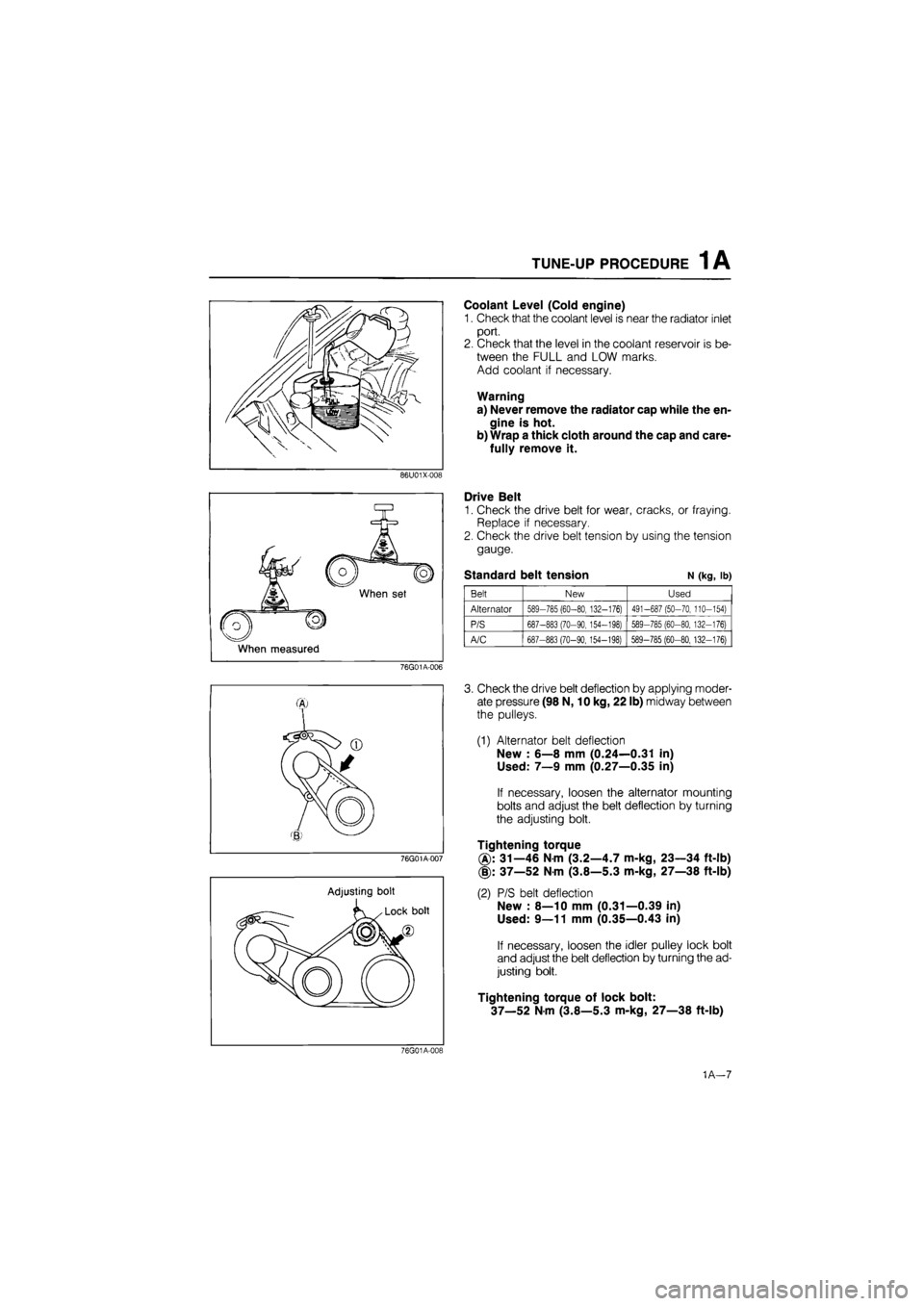
Coolant Level (Cold engine)
1. Check that the coolant level is near the radiator inlet
port.
2. Check that the level in the coolant reservoir is be-
tween the FULL and LOW marks.
Add coolant if necessary.
Warning
a) Never remove the radiator cap while the en-
gine is hot.
b) Wrap a thick cloth around the cap and care-
fully remove it.
86U01X-008
When set
When measured
Drive Belt
1. Check the drive belt for wear, cracks, or fraying.
Replace if necessary.
2. Check the drive belt tension by using the tension
gauge.
Standard belt tension N (kg, lb)
Belt New Used
Alternator 589-785 (60-80, 132-176) 491-687 (50-70, 110-154)
P/S 687-883 (70-90, 154-198) 589-785 (60-80, 132-176)
A/C 687-883 (70-90,154-198) 589-785 (60-80, 132-176)
76G01A-006
76G01A-007
Adjusting bolt
3. Check the drive belt deflection by applying moder-
ate pressure (98 N, 10 kg, 22 lb) midway between
the pulleys.
(1) Alternator belt deflection
New : 6—8 mm (0.24—0.31 in)
Used: 7—9 mm (0.27—0.35 in)
If necessary, loosen the alternator mounting
bolts and adjust the belt deflection by turning
the adjusting bolt.
Tightening torque
31—46 Nm (3.2—4.7 m-kg, 23—34 ft-lb)
(§): 37—52 Nm (3.8—5.3 m-kg, 27—38 ft-lb)
(2) P/S belt deflection
New : 8—10 mm (0.31—0.39 in)
Used: 9—11 mm (0.35—0.43 in)
If necessary, loosen the idler pulley lock bolt
and adjust the belt deflection by turning the ad-
justing bolt.
Tightening torque of lock bolt:
37—52 Nm (3.8—5.3 m-kg, 27—38 ft-lb)
76G01A-019
1A—7
Page 131 of 1865

INSTALLATION 1A
76G01A-099
76G01A-100
Air Cleaner Assembly
1. Install the air cleaner assembly.
Tightening torque:
16—27
N
m (1.6—2.8 m-kg, 12—20 ft-lb)
2. Connect the air flow sensor connector and air in-
take pipe (Fl).
Engine Oil
Add the specified amount and type of engine oil. (Re-
fer to Section 2A.)
Coolant
Close the drain plug, fill the radiator and reservoir tank
with the specified amount and type of coolant. (Re-
fer to Section 3A.)
Check Engine Condition
1. Check for leaks.
2. Perform engine adjustments if necessary.
3. Perform a road test.
4. Recheck the oil and coolant levels.
86U01X-204
1A—99
Page 137 of 1865

1B TUNE-UP PROCEDURE 1 B
86U01X-008
Coolant Level (Cold engine)
1. Check that the coolant level is near the radiator inlet
port.
2. Check that the level in the coolant reservoir is be-
tween the FULL and LOW marks.
Add coolant if necessary.
Warning
a) Never remove the radiator cap while the en-
gine is hot.
b) Wrap a thick cloth around the cap and care-
fully remove it.
Drive Belt
1. Check that the drive belt is positioned in the pul-
ley groove.
2. Check the drive belt for wear, cracks, or fraying.
Replace if necessary.
3. Check the drive belt tension by using the tension
gauge.
Standard belt tension N (kg, lb)
76G01B-006
Belt New Used
Alternator 589-785 (60-80, 132-176) 491-687 (50-70, 110-154)
P/S 687-883 (70-90,154-198) 589-785 (60-80.132-176)
A/C 687-883 (70-90,154-198) 589-785 (60-80,132-176)
76G01B-007
Adjusting bolt
76G01B-008
4. Check the drive belt deflection by applying moder-
ate pressure (98 N, 10 kg, 22 lb) midway between
the pulleys.
(1) Alternator belt deflection
New : 6—8 mm (0.24—0.31 in)
Used: 7—9 mm (0.27—0.35 in)
If necessary, loosen the alternator mounting
bolts and adjust the belt deflection by turning
the adjusting bolt.
Tightening torque
®: 31—46 Nm (3.2—4.7 m-kg, 23—34 ft-lb)
(§): 37—52 Nm (3.8—5.3 m-kg, 27—38 ft-lb)
(2) P/S belt deflection
New : 8—10 mm (0.31—0.39 in)
Used: 9—11 mm (0.35—0.43 in)
If necessary, loosen the idler pulley lock bolt
and adjust the belt deflection by turning the ad-
justing bolt.
Tightening torque of lock bolt:
37—52 N-m (3.8—5.3 m-kg, 27—38 ft-lb)
1B—6
Page 212 of 1865

INSTALLATION 1B
76G01A-100
Air Cleaner Assembly
1. Install the air cleaner assembly.
Tightening torque:
16—27
N
m (1.6—2.8 m-kg, 12—20 ft-lb)
2. Connect the air flow sensor connector and air in-
take pipe.
Engine Oil
Add the specified amount and type of engine oil. (Re-
fer to Section 2A.)
Coolant
Close the drain plug, fill the radiator and reservoir tank
with the specified amount and type of coolant. (Re-
fer to Section 3A.)
Check Engine Condition
1. Check for leaks.
2. Perform engine adjustments if necessary.
3. Perform a road test.
4. Recheck the oil and coolant levels.
86U01X-204
1B-81
Page 311 of 1865

INSTALLATION 1C
Accelerator Cable
Install the accelerator cable.
76G01C-235
76G01C-236
Engine Oil
Add the specified amount and type of engine oil. (Re-
fer to Section 2B)
Coolant
Close the drain plug, fill the radiator and reservoir tank
with the specified amount and type of coolant. (Re-
fer to Section 3B)
Check Engine Condition
1. Check for leaks.
2. Perform engine adjustments if necessary.
3. Perform a road test.
4. Recheck the oil and coolant levels.
1C—99
Page 341 of 1865

3A OUTLINE
OUTLINE
COOLANT FLOW CHART (DOHC)
ISC solenoid valve 2-stage thermostat
From jo heater heater Main*™, valve ^--^Sub valve
76G03A-002
1. Water pump
2. Thermostat
3. Radiator
4. Coolant reservoir
5. Oil cooler
6. Cooling fan
3A—2