1987 MAZDA 626 wiring diagram
[x] Cancel search: wiring diagramPage 2 of 1865
Mazda
626
Workshop
Manual
FOREWORD
This workshop manual is intended for use
by service technicians of authorized Mazda
dealers to help them service Mazda vehicles.
This manual can be also useful in diagnosing
certain problems and performing some repair
and maintenance on Mazda vehicles.
For proper repair and maintenance, it is im-
portant to be thoroughly familiarized with this
manual. It is recommended that this manual al-
ways be kept in a handy place for quick and
easy reference.
All the contents of this manual, including pho-
tographs, drawings, and specifications, are the
latest available at the time of printing. As modifi-
cations affecting repair or maintenance occur,
relevant information supplementary to this
volume will be made available at Mazda deal-
ers. This manual should be kept up-to-date.
Mazda Motor Corporation reserves the right
to alter the specifications and contents of this
manual without obligation or advance notice.
All rights reserved. No part of this book may
be reproduced or utilized in any form or by any
means, electronic or mechanical, including
photocopying, recording, or by any informa-
tion storage and retrieval system, without per-
mission in writing.
Mazda Motor Corporation
HIROSHIMA JAPAN
Refer to the following wiring diagrams if
necessary.
Refer to From No.
5095-10-87 G L.H.D.
5096-10-87 G R.H.D.
5096-20-871 Germany
5095-30-871 French
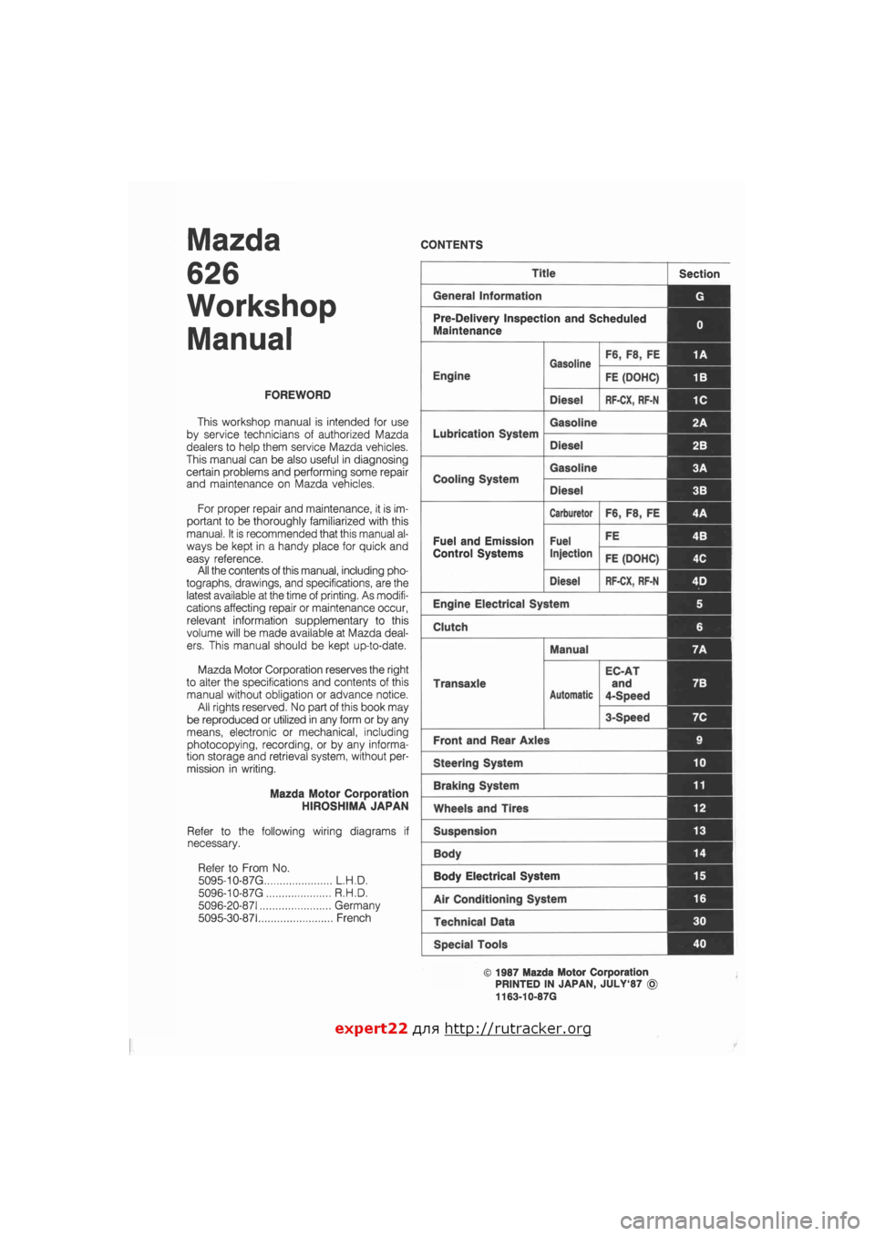
CONTENTS
Title Section
General Information G
Pre-Delivery Inspection and Scheduled
Maintenance 0
Gasoline F6, F8, FE 1A
Engine
Gasoline
FE (DOHC) 1B
Diesel RF-CX, RF-N 1C
Lubrication System
Gasoline 2A
Lubrication System
Diesel 2B I
Cooling System
Gasoline 3A 1
Cooling System
Diesel 3B
Carburetor F6, F8, FE 4A
Fuel and Emission Fuel FE 4B I
Control Systems Injection FE (DOHC) 4C
Diesel RF-CX, RF-N 4D j
Engine Electrical System 5
Clutch 6
Manual 7A
Transaxle
Automatic
EC-AT
and
4-Speed
7B
3-Speed 7C
Front and Rear Axles 9
Steering System 10
Braking System 11
Wheels and Tires 12
Suspension 13
Body 14 |
Body Electrical System 15
Air Conditioning System 16
Technical Data 30
Special Tools 40
© 1987 Mazda Motor Corporation
PRINTED IN JAPAN, JULY'87 ©
1163-10-87G
expert22 flna http://rutracker.org
Page 476 of 1865

4B TROUBLESHOOTING WITH SST
If a malfunction code number is shown on the SST, check the following chart along with the wiring
diagram.
Code No. 01 (Ignition pulse) PC: Possible Cause
76G04B-009
4B—14
Page 1393 of 1865
11
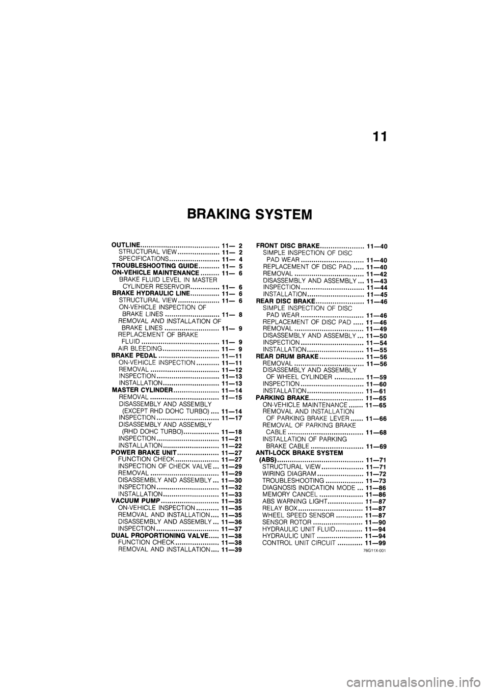
BRAKING SYSTEM
OUTLINE 11—2
STRUCTURAL VIEW 11—2
SPECIFICATIONS 11— 4
TROUBLESHOOTING GUIDE 11— 5
ON-VEHICLE MAINTENANCE 11—6
BRAKE FLUID LEVEL IN MASTER
CYLINDER RESERVOIR 11— 6
BRAKE HYDRAULIC LINE 11—6
STRUCTURAL VIEW 11—6
ON-VEHICLE INSPECTION OF
BRAKE LINES 11— 8
REMOVAL AND INSTALLATION OF
BRAKE LINES 11— 9
REPLACEMENT OF BRAKE
FLUID 11— 9
AIR BLEEDING 11— 9
BRAKE PEDAL 11—11
ON-VEHICLE INSPECTION 11—11
REMOVAL 11—12
INSPECTION 11—13
INSTALLATION 11—13
MASTER CYLINDER 11—14
REMOVAL 11—15
DISASSEMBLY AND ASSEMBLY
(EXCEPT RHD DOHC TURBO).... 11—14
INSPECTION 11—17
DISASSEMBLY AND ASSEMBLY
(RHD DOHC TURBO) 11—18
INSPECTION 11—21
INSTALLATION 11—22
POWER BRAKE UNIT 11—27
FUNCTION CHECK 11—27
INSPECTION OF CHECK VALVE... 11—29
REMOVAL 11—29
DISASSEMBLY AND ASSEMBLY... 11—30
INSPECTION 11—32
INSTALLATION 11—33
VACUUM PUMP 11—35
ON-VEHICLE INSPECTION 11—35
REMOVAL AND INSTALLATION.... 11—35
DISASSEMBLY AND ASSEMBLY... 11—36
INSPECTION 11—37
DUAL PROPORTIONING VALVE 11—38
FUNCTION CHECK 11—38
REMOVAL AND INSTALLATION.... 11—39
FRONT DISC BRAKE 11—40
SIMPLE INSPECTION OF DISC
PAD WEAR 11—40
REPLACEMENT OF DISC PAD 11—40
REMOVAL 11—42
DISASSEMBLY AND ASSEMBLY... 11—43
INSPECTION 11—44
INSTALLATION 11—45
REAR DISC BRAKE 11—46
SIMPLE INSPECTION OF DISC
PAD WEAR 11—46
REPLACEMENT OF DISC PAD 11—46
REMOVAL 11—49
DISASSEMBLY AND ASSEMBLY... 11—50
INSPECTION 11—54
INSTALLATION 11—55
REAR DRUM BRAKE 11—56
REMOVAL 11—56
DISASSEMBLY AND ASSEMBLY
OF WHEEL CYLINDER 11—59
INSPECTION 11—60
INSTALLATION 11—61
PARKING BRAKE 11—65
ON-VEHICLE MAINTENANCE 11—65
REMOVAL AND INSTALLATION
OF PARKING BRAKE LEVER 11—66
REMOVAL OF PARKING BRAKE
CABLE 11—68
INSTALLATION OF PARKING
BRAKE CABLE 11—69
ANTI-LOCK BRAKE SYSTEM
(ABS) 11—71
STRUCTURAL VIEW 11—71
WIRING DIAGRAM 11—72
TROUBLESHOOTING 11—73
DIAGNOSIS INDICATION MODE ... 11—86
MEMORY CANCEL 11—86
ABS WARNING LIGHT 11—87
RELAY BOX 11—87
WHEEL SPEED SENSOR 11—87
SENSOR ROTOR 11—90
HYDRAULIC UNIT FLUID 11—94
HYDRAULIC UNIT 11—94
CONTROL UNIT CIRCUIT 11—99
76G11X-001
Page 1464 of 1865
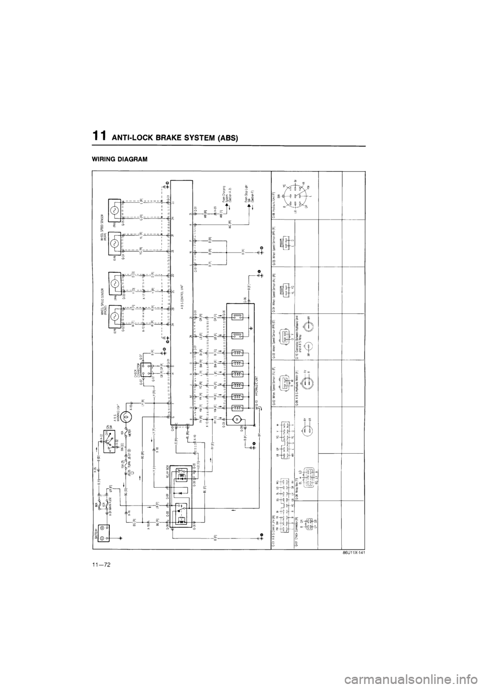
1 1 ANTI-LOCK BRAKE SYSTEM (ABS)
WIRING DIAGRAM
o--
m o--
u
£
s-i J-
=—g ^t—• ¥—o
in
3—0 OH
i-i iH
s—0
Q-g
"-i o---s—0 b-t
ii
I—
---OD— -i-OB--
—HI
H:
86U11X-141
11—72
Page 1468 of 1865
1 1 ANTI-LOCK BRAKE SYSTEM (ABS)
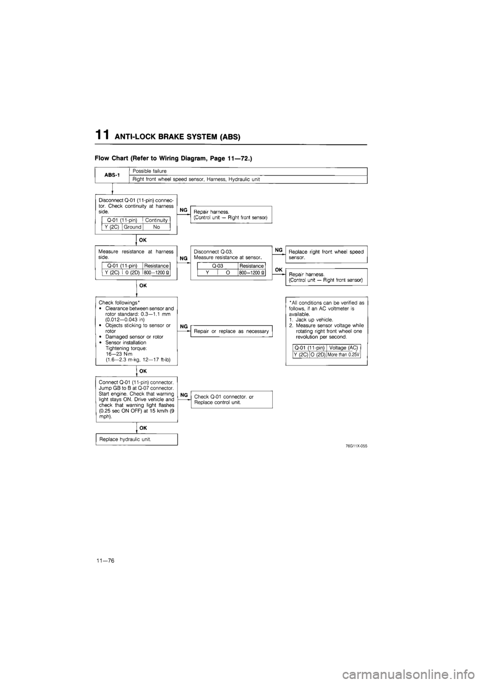
Flow Chart (Refer to Wiring Diagram, Page 11—72.)
ABS-1
Possible failure
Right front wheel speed sensor, Harness, Hydraulic unit
Disconnect Q-01 (11-pin) connec-tor. Check continuity
at
harness side.
Q-01 (11-pin)
I
Continuity
Y (2C) Ground No
OK
Measure resistance
at
harness side.
Q-01 (11-pin) Resistance
Y (2C)
i 0
(2D) 800—1200
Q
OK
NG
Repair harness.
(Control unit — Right front sensor)
NG
Disconnect Q-03. Measure resistance
at
sensor.
Q-03 Resistance
Y
[ O
800—1200 Q
NG
Replace right front wheel speed sensor.
OK
Repair harness.
(Control unit — Right front sensor)
Check followings*
• Clearance between sensor and rotor standard: 0.3—1.1
mm
(0.012-0.043
in)
• Objects sticking
to
sensor
or
rotor
• Damaged sensor
or
rotor
• Sensor installation Tightening torque: 16-23 N-m (1.6-2.3 m-kg, 12—17 ft-lb)
OK
Connect Q-01 (11-pin) connector. Jump GB
to B at
Q-07 connector. Start engine. Check that warning light stays ON. Drive vehicle and check that warning light flashes (0.25 sec ON OFF)
at 15
km/h
(9
mph).
NG
Repair
or
replace
as
necessary
* All conditions can
be
verified
as
follows,
if an AC
voltmeter
is
available. 1. Jack
up
vehicle. 2. Measure sensor voltage while rotating right front wheel
one
revolution
per
second.
Q-01 (11-Din) Voltage (AC)
Y (2C) O (2D) More than 0.25V
NG
Check Q-01 connector,
or
Replace control unit.
OK
Replace hydraulic unit.
76G11X-055
11—76
Page 1657 of 1865
15 INTRODUCTION
INTRODUCTION
HOW TO USE THIS SECTION
Information regarding removal and installation of electrical equipment is given in SECTION 14.
Understanding will be easier if this section is used in conjunction with the WIRING DIAGRAMS.
63U15X-002
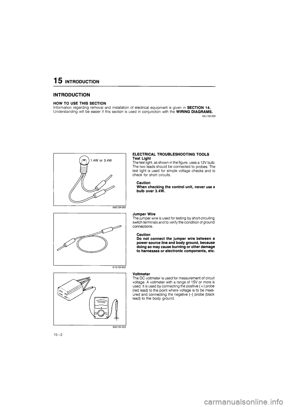
ELECTRICAL TROUBLESHOOTING TOOLS
Test Light
The test light, as shown in the figure, uses a 12V bulb.
The two leads should be connected to probes. The
test light is used for simple voltage checks and to
check for short circuits.
Caution
When checking the control unit, never use a
bulb over 3.4W.
69G15X-002
Jumper Wire
The jumper wire is used for testing by short-circuiting
switch terminals and to verify the condition of ground
connections.
Caution
Do not connect the jumper wire between a
power source line and body ground, because
doing so may cause burning or other damage
to harnesses or electronic components, etc.
61G15X-002
Voltmeter
The DC voltmeter is used for measurement of circuit
voltage. A voltmeter with a range of 15V or more is
used. It is used by connecting the positive (+) probe
(red lead) to the point where voltage is to be meas-
ured and connecting the negative (-) probe (black
lead) to the body ground.
69G15X-003
15—2
Page 1711 of 1865
1 5 PANEL LIGHT CONTROL
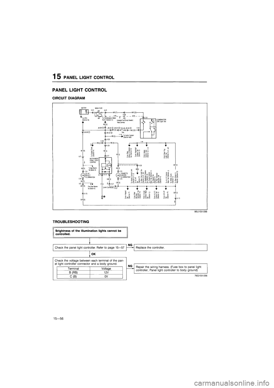
PANEL LIGHT CONTROL
CIRCUIT DIAGRAM
COMBINATION SW (Light Sw)
1 ? 3= o
5
B
*
SB c
52 "
o
-too u c E o E H Eil'y E 1 a tcsfi
86U15X-098
TROUBLESHOOTING
OK
Repair the wiring harness. (Fuse box
to
panel light controller, Panel light controller
to
body ground)
76G15X-056
15—56
Check the voltage between each terminal
of
the pan-el light controller connector and
a
body ground.
Terminal Voltage
B (RB) 12V
C(B) OV
Page 1749 of 1865
1 5 AUTO ADJUSTING SUSPENSION (AAS)
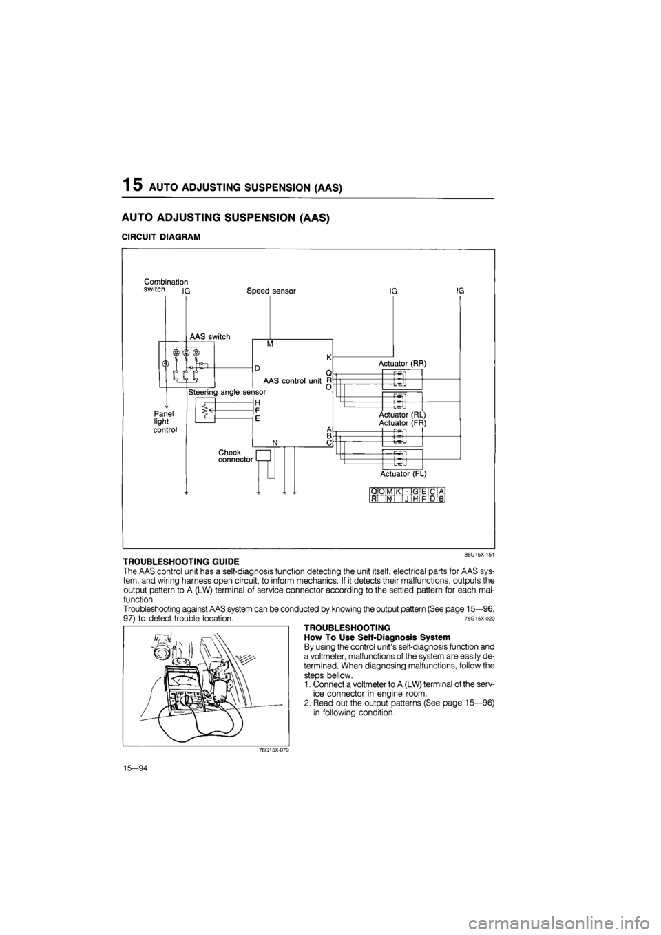
AUTO ADJUSTING SUSPENSION (AAS)
CIRCUIT DIAGRAM
Combination switch iq Speed sensor
M
Panel light
control
AAS control unit
Steering angle sensor
H
N
Check connector
IG IG
Actuator (RR)
-P-Sl
-t-^J
—Pwsl
Actuator (RL)
Actuator (FR) P5fl
+
Actuator (FL)
QO M K GIE C A
ft N J HI F D B
86U15X-151
TROUBLESHOOTING GUIDE
The AAS control unit has a self-diagnosis function detecting the unit itself, electrical parts for AAS sys-
tem, and wiring harness open circuit, to inform mechanics. If it detects their malfunctions, outputs the
output pattern to A (LW) terminal of service connector according to the settled pattern for each mal-
function.
Troubleshooting against AAS system can be conducted by knowing the output pattern (See page 15—96,
97) to detect trouble location. 76gisx-o2o
TROUBLESHOOTING
How To Use Self-Diagnosis System
By using the control unit's self-diagnosis function and
a voltmeter, malfunctions of the system are easily de-
termined. When diagnosing malfunctions, follow the
steps bellow.
1. Connect a voltmeter to A (LW) terminal of the serv-
ice connector in engine room.
2. Read out the output patterns (See page 15—96)
in following condition.
76G15X-079
15—94