Page 1547 of 1865

1 3 FRONT WHEEL ALIGNMENT
FRONT WHEEL ALIGNMENT
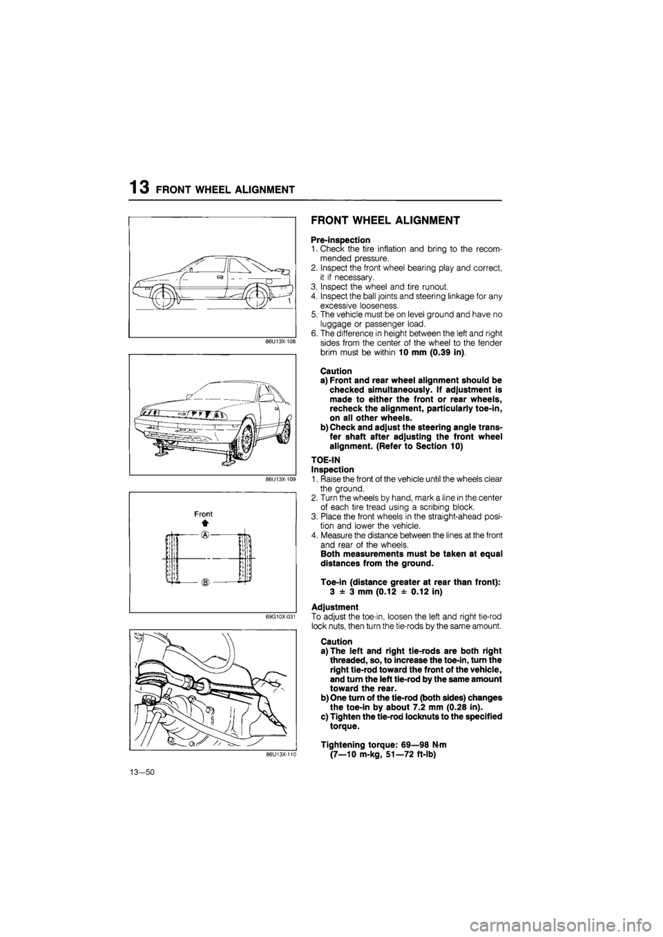
86U13X-108
69G10X-031
Pre-inspection
1. Check the tire inflation and bring to the recom-
mended pressure.
2. Inspect the front wheel bearing play and correct,
it if necessary.
3. Inspect the wheel and tire runout.
4. Inspect the ball joints and steering linkage for any
excessive looseness.
5. The vehicle must be on level ground and have no
luggage or passenger load.
6. The difference in height between the left and right
sides from the center of the wheel to the fender
brim must be within 10 mm (0.39 in).
Caution
a) Front and rear wheel alignment should be
checked simultaneously. If adjustment is
made to either the front or rear wheels,
recheck the alignment, particularly toe-in,
on all other wheels.
b) Check and adjust the steering angle trans-
fer shaft after adjusting the front wheel
alignment. (Refer to Section 10)
TOE-IN
Inspection
1. Raise the front of the vehicle until the wheels clear
the ground.
2. Turn the wheels by hand, mark a line in the center
of each tire tread using a scribing block.
3. Place the front wheels in the straight-ahead posi-
tion and lower the vehicle.
4. Measure the distance between the lines at the front
and rear of the wheels.
Both measurements must be taken at equal
distances from the ground.
Toe-in (distance greater at rear than front):
3 ± 3 mm (0.12 ± 0.12 in)
Adjustment
To adjust the toe-in, loosen the left and right tie-rod
lock nuts, then turn the tie-rods by the same amount.
Caution
a) The left and right tie-rods are both right
threaded, so, to increase the toe-in, turn the
right tie-rod toward the front of the vehicle,
and turn the left tie-rod by the same amount
toward the rear.
b) One turn of the tie-rod (both sides) changes
the toe-in by about 7.2 mm (0.28 in).
c) Tighten the tie-rod locknuts to the specified
torque.
Tightening torque: 69—98 N-m
(7—10 m-kg, 51—72 ft-lb) 86U13X-110
13-50
Page 1549 of 1865

13 REAR WHEEL ALIGNMENT
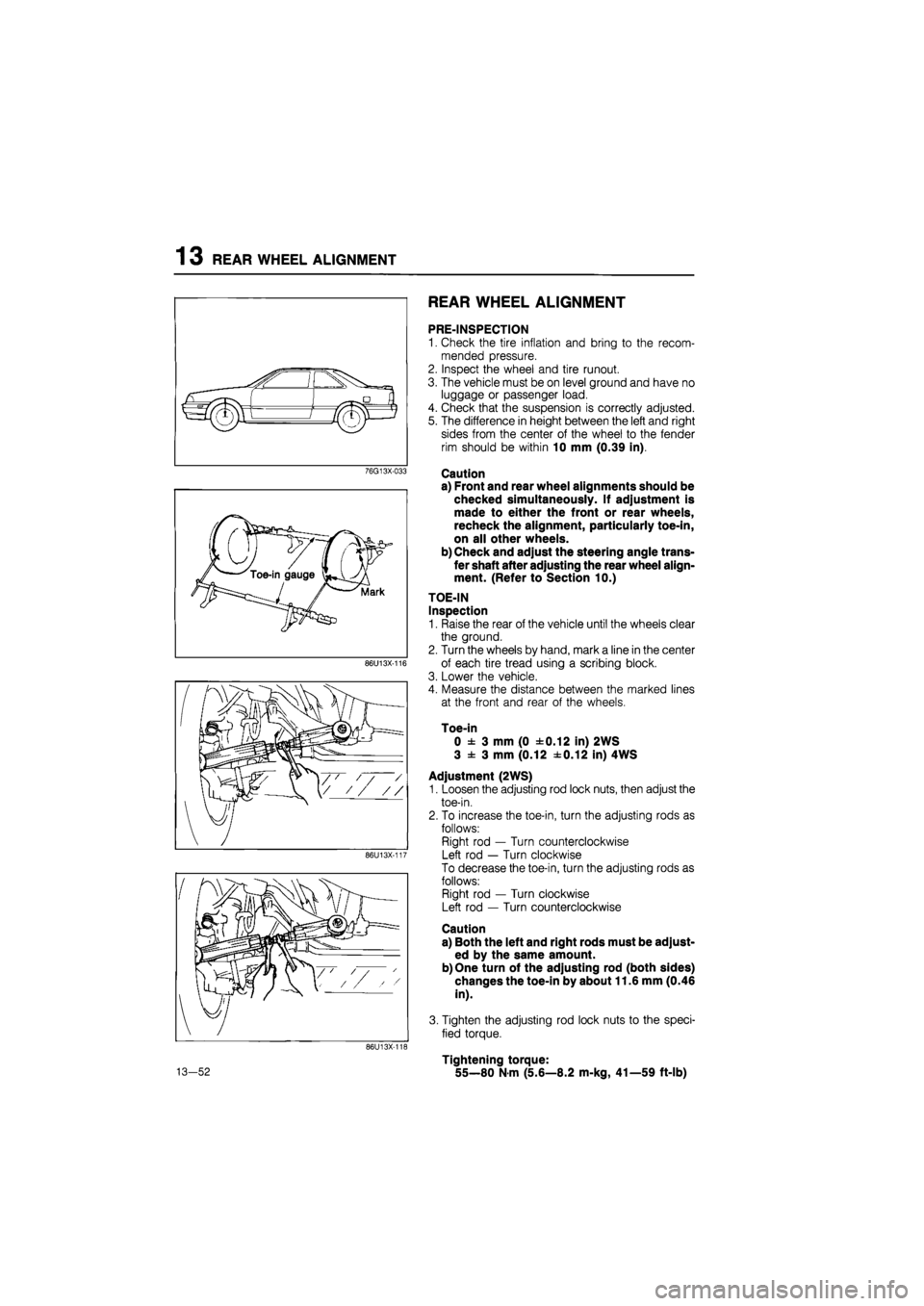
76G13X-033
86U13X-116
86U13X-117
86U13X-116
13-52
REAR WHEEL ALIGNMENT
PRE-INSPECTION
1. Check the tire inflation and bring to the recom-
mended pressure.
2. Inspect the wheel and tire runout.
3. The vehicle must be on level ground and have no
luggage or passenger load.
4. Check that the suspension is correctly adjusted.
5. The difference in height between the left and right
sides from the center of the wheel to the fender
rim should be within 10 mm (0.39 in).
Caution
a) Front and rear wheel alignments should be
checked simultaneously. If adjustment is
made to either the front or rear wheels,
recheck the alignment, particularly toe-in,
on all other wheels.
b) Check and adjust the steering angle trans-
fer shaft after adjusting the rear wheel align-
ment. (Refer to Section 10.)
TOE-IN
Inspection
1. Raise the rear of the vehicle until the wheels clear
the ground.
2. Turn the wheels by hand, mark a line in the center
of each tire tread using a scribing block.
3. Lower the vehicle.
4. Measure the distance between the marked lines
at the front and rear of the wheels.
Toe-in
0 ± 3 mm (0 ±0.12 in) 2WS
3 ± 3 mm (0.12 ±0.12 in) 4WS
Adjustment (2WS)
1. Loosen the adjusting rod lock nuts, then adjust the
toe-in.
2. To increase the toe-in, turn the adjusting rods as
follows:
Right rod — Turn counterclockwise
Left rod — Turn clockwise
To decrease the toe-in, turn the adjusting rods as
follows:
Right rod — Turn clockwise
Left rod — Turn counterclockwise
Caution
a) Both the left and right rods must be adjust-
ed by the same amount.
b) One turn of the adjusting rod (both sides)
changes the toe-in by about 11.6 mm (0.46
in).
3. Tighten the adjusting rod lock nuts to the speci-
fied torque.
Tightening torque:
55—80 N-m (5.6—8.2 m-kg, 41—59 ft-lb)
Page 1639 of 1865
1 4 SLIDING SUNROOF
76U14X-067
Set plate
76U14X-068
1.5mm (0.016 in)
: ? ©—
A-A Cross section
76U14X-069
B-B Cross section
Adjust screw Fitting screw jj
Fitting screw®
14. Fully close the lower panel.
15. Install the slide panel to the lower panel, and tight-
en securely.
16. Insert the sun shade from the notch in the set plate,
and push it all the way back.
17. Insert the set plate cap.
18. Adjust the height of the slide panel.
(Cross-section A-A)
Adjust so that the height difference between the
outer panel and roof panel is 1.5 mm (0.06 in)
max.
(Cross-section B-B adjustment)
(1) Loosen installation screws (1) and (2).
If the adjustment is only about 2 mm (0.08 in)
don't loosen screw (1).
(2) Turn the screws to adjust.
Turning to the right raises, and to the left lowers.
(3) Tighten installation screws (1) and (2).
76U14X-070
14-88
Page 1644 of 1865
WINDSHIELD WIPER 1 4
INSTALLATION
Install in the reverse order of removal.
Note
The wiper arms are identified by marks on the
arms.
DL: driver side
PL: passenger side
76G14X-047
25 ± 5 mm
(0.98 ± 25 ± 5 mm
0.19 in) (0.98 ± 0.19 in)
ADJUSTMENT
Arm Height
Set the arm height as shown in the figure.
86U14X-173
Adjustment of washer spray
Inserting a needle or similar object into the nozzle hole
and bend to change the spray direction.
268 + 50 mm (10.6 + 1.97 in)
86U14X-174
14—93
Page 1647 of 1865
14 REAR WINDOW WIPER
(0.98 ±0.19 in)
ADJUSTMENT
Arm Height
Set the height as shown in the figure.
86U14X-180
o
r ^
660 mm
(25.98 in)
Adjustment of washer spray
Insert a needle or similar object into the nozzle hole
and bend to change the spray direction.
86U14X-181
14—96