Page 220 of 1865

1C TUNE-UP PROCEDURE
Comprex supercharger
Deflection mm (in)
New 4 0-6.0 (0.16—0.23)
Used 8.0-10 0 (0 31-0.39)
If necessary, loosen the idler lock nut and adjust
the belt deflection by turning the adjust bolt.
Tightening torque:
16—23 Nm (1.6—2.3 m-kg, 12—17 ft-lb)
76G01C-011
o
INJECTION TIMING
1. Disconnect the negative battery cable.
2. Release the CSD using the screw driver.
3. Remove the cover on the clutch housing.
4. Turn the flywheel and set the indicator at ATDC.
5. Disconnect the injection pipes from the injection
pump.
76G04D-008
6. Remove the hydraulic head plug from the injec-
tion pump.
7. Mount the SST into the plug hole on the hydraulic
head so the tip of the dial gauge pointer touches
the plunger end of the pump and the dial gauge
indicates approx. 2.0 mm (0.08 in).
76G04D-009
8. Turn the crankshaft slowly counterclockwise to
30-50° BTDC.
9. Make sure the dial indicator pointer no longer
moves by slightly turning the crankshaft.
10. Set the dial gauge scale to Zero at the pointer.
76G04D-010
1C-8
Page 676 of 1865

ON-VEHICLE MAINTENANCE 4D
INJECTION TIMING
1. Disconnect the negative battery cable.
2. Release the CSD using the screw driver.
3. Remove the cover on the clutch housing.
4. Turn the flywheel and set the indicator at TDC.
5. Disconnect the injection pipes from the injection
pump.
76G04D-008
6. Remove the hydraulic head plug from the injec-
tion pump.
7. Mount the SST into the plug hole on the hydraulic
head so the tip of the dial gauge pointer touches
the plunger end of the pump and the dial gauge
indicates approx. 2.0 mm (0.08 in).
76.G04D-009
8. Turn the crankshaft slowly counterclockwise to
30—50° BTDC.
9. Make sure the dial indicator pointer no longer
moves by slightly turning the crankshaft.
10. Set the dial gauge scale to Zero at the pointer.
76G04D-010
11. Turn the crankshaft clockwise to align the indica-
tor pin at ATDC 1° (RF-CX), TDC 0° (RF-N).
12. Read the dial gauge.
Cam lift: 0.98—1.02 mm (0.038—0.040 in)
13. If not within the specification, adjust the injection
timing. (Refer to page 4D—24.)
76G04D-011
4D-5
Page 696 of 1865
FUEL SYSTEM 4D
RF-CX
o
M
o
10-
RF-N
M
m
M
o TO"
5-
76G04D-059
76G04D-060
76G04D-061
3. Turn the crankshaft, and align the flywheel indica-
tor pin at ATDC 10 (RF-CX), or TDC 0° (RF-N).
4. Turn the injection pump until the dial indicator in-
dicates 1 mm (0.04 in).
Note
Refer to page 4D—4 for initial setting of the
dial indicator.
Cam Height Inspection
1. Set the SST into the injection pump as for injec-
tion timing adjustment. (Refer to page 4D—4.)
2. Turn the crankshaft clockwise and read the maxi-
mum difference of the indicator value, which gives
the cam height.
Cam height: 2.2 mm (0.08 in)
76G04D-062
4D—25
Page 1439 of 1865

REAR DISC BRAKE 1 1
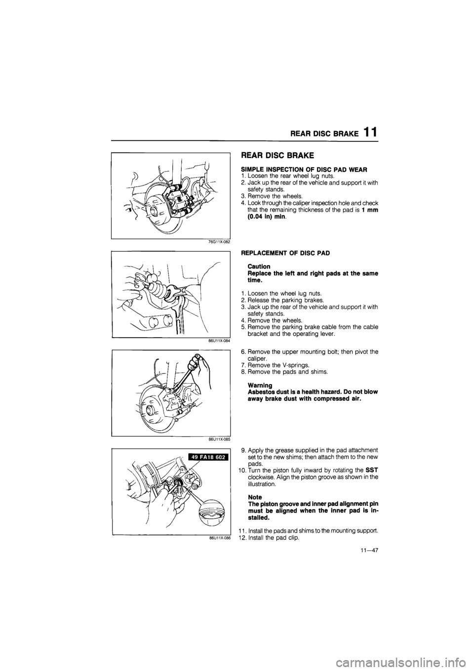
REAR DISC BRAKE
SIMPLE INSPECTION OF DISC PAD WEAR
1. Loosen the rear wheel lug nuts.
2. Jack up the rear of the vehicle and support it with
safety stands.
3. Remove the wheels.
4. Look through the caliper inspection hole and check
that the remaining thickness of the pad is 1 mm
(0.04 in) min.
76G11X-082
86U11X-084
REPLACEMENT OF DISC PAD
Caution
Replace the left and right pads at the same
time.
1. Loosen the wheel lug nuts.
2. Release the parking brakes.
3. Jack up the rear of the vehicle and support it with
safety stands.
4. Remove the wheels.
5. Remove the parking brake cable from the cable
bracket and the operating lever.
6. Remove the upper mounting bolt; then pivot the
caliper.
7. Remove the V-springs.
8. Remove the pads and shims.
Warning
Asbestos dust is a health hazard. Do not blow
away brake dust with compressed air.
86U11X-085
86U11X-086
9. Apply the grease supplied in the pad attachment
set to the new shims; then attach them to the new
pads.
10. Turn the piston fully inward by rotating the SST
clockwise. Align the piston groove as shown in the
illustration.
Note
The piston groove and inner pad alignment pin
must be aligned when the inner pad is in-
stalled.
11. Install the pads and shims to the mounting support.
12. Install the pad clip.
11—47