1987 MAZDA 626 ignition
[x] Cancel search: ignitionPage 932 of 1865

7B ELECTRICAL SYSTEM COMPONENTS
76G07B-073
7B-66
3. Remove the screw and move the inhibitor switch
so that the small hole is aligned with the screw hole.
4. Set the alignment by inserting a 2.0 mm (0.079
in) diameter pin through the holes.
5. Loosely tighten the switch mounting bolts, remove
the pin, and reinstall the screw.
6. Tighten the switch mounting bolts to specification.
Tightening torque:
8—11 N-m (80—110 cm-kg, 69—95 in-lb)
7. Recheck the continuity of the individual terminals.
WATER TEMPERATURE SWITCH
Inspection
1. Remove the water temperature switch.
2. Place the switch in water with a thermometer and
heat up the water gradually.
3. Check the continuity of the terminals. If necessary
replace the switch.
Connection guide
Water temperature Continuity
Below 65°C (149°F) Yes
Above 72°C (162°F) \ No
FLUID TEMPERATURE SWITCH (G4A-EL)
Inspection
1. Remove the fluid temperature switch.
2. Place the switch in oil with a thermometer as shown
and heat it up gradually.
3. Check the continuity of the terminals. If necessary
replace the switch.
Connection guide
Fluid temperature Continuity
Above 150°C (302°F) Yes
Below 143°C (289°F) No
BRAKE LIGHT SWITCH (G4A-EL)
Inspection of Terminal Voltage
1. Turn the ignition switch ON.
2. Check the voltage between terminal (WG) and
ground while depressing the brake pedal.
Terminal voltage I Brake pedal
Approx. 12V Depressed
Below 1,5V Released
3. If not correct, check continuity of the switch.
Page 933 of 1865

ELECTRICAL SYSTEM COMPONENTS 7B
Inspection of Continuity
1. Disconnect the brake light switch connector.
2. Check for continuity between the terminals while
depressing the brake pedal.
79G07C-114
76G07B-076
KICK-DOWN SWITCH (G4A-HL)
Inspection of Terminal Voltage
1. Turn the ignition switch ON.
2. Check the voltage at terminal (V) with a voltmeter.
Depressing stroke Terminal voltage
7/8-8/8 (Full) Approx. 12V
0-7/8 Below 1,5V
3. If not correct, check the wiring harness, switch, or
adjust the switch position.
Inspection of Continuty
1. Disconnect the kick-down switch connector.
2. Check for continuity of the switch with an
ohmmeter.
Switch Continuity
Pushed Yes
Released No
3. If not correct, replace the kick-down switch.
76G07B-077
Adjustment
1. Loosen the kick-down switch locknuts.
2. Depress the accelerator pedal fully.
3. Turn the switch until the threaded case touches the
stopper.
4. Turn the switch counterclockwise by one half revo-
lution.
5. Secure the switch with the locknut.
76G07B-078
7B—67
Page 934 of 1865

7B ELECTRICAL SYSTEM COMPONENTS
76G07B-079
76G07B-080
76G07B-081
PULSE GENERATOR (G4A-EL)
Inspection
1. Disconnect the pulse generator connector.
2. Check for continuity between the terminals, if
necessary replace the pulse generator.
Resistance: 200—400fl
VEHICLE SPEED SENSOR (G4A-EL)
Inspection of voltage
1. Connect a voltmeter between the 1Q terminal of
the EC-AT control unit and ground as shown.
2. Turn the ignition switch ON.
3. Remove the speedometer cable from the transaxle.
4. Slowly turn the speedometer cable one turn.
5. Check that approx. 4.5V is shown 4 times.
6. If not correct, check the combination meter.
CRUISE CONTROL SWITCH (CRUISE CONTROL
UNIT)
Refer to Section 15.
IDLE SWITCH AND THROTTLE SENSOR
(G4A-EL)
Refer to Section 4A.
OD RELEASE SOLENOID VALVE (G4A-HL)
Inspection of Resistance
1. Disconnect the solenoid valve connector.
2. Check resistance between the terminals.
Resistance: 13—27 ft
3. If not correct, replace the solenoid valve.
76G07B-082
7B-68
Page 936 of 1865

7B ELECTRICAL SYSTEM COMPONENTS
Terminal Connected to Voltage Condition
1J — — —
1K — — —
1L (Input) Idle switch Below 1.5V At idle 1L (Input) Idle switch Approx. 12V Other speeds
1M — — —
1N (Input) Brake light switch Approx. 12V Brake pedal depressed 1N (Input) Brake light switch Below 1.5V Brake pedal released
10 (Input) Throttle sensor
Approx. 5V Ignition switch ON 10 (Input) Throttle sensor Below 1,5V Ignition switch OFF
1P (Input)
Throttle sensor
Approx. 0.5—4.3V Throttle valve fully closed to fully open
1Q (Input) Vehicle speed sensor
Approx. 4.5V During driving
1Q (Input) Vehicle speed sensor Approx. 4.5V or below 1.5V Vehicle stopped
1R (Ground) Throttle sensor Below 1,5V —
1S (Input) Pulse generator Approx. 12V Engine running 1S (Input) Pulse generator Below 1,5V Engine stopped
1S (Ground) Pluse generator Below 1.5V —
2A (Battery power) Battery Approx. 12V Ignition switch ON 2A (Battery power) Battery Below 1,5V Ignition switch OFF
2B (Ground) Body ground Below 1,5V —
2C (Memory power) Battery Approx. 12V —
2D (Ground) Body ground Below 1,5V —
2E (Output) 1-2 shift solenoid valve Approx. 12V
Refer to page 7B—26 of solenoid valve
operation table
2E (Output) 1-2 shift solenoid valve Below 1.5V Refer to page 7B—26 of solenoid valve
operation table
2F (Output) 2-3 shift solenoid valve Approx. 12V
Refer to page 7B—26 of solenoid valve
operation table
2F (Output) 2-3 shift solenoid valve Below 1,5V
Refer to page 7B—26 of solenoid valve
operation table
2G — — —
2H (Output) 3-4 shift solenoid valve Approx. 12V Refer to page 7B—26 of solenoid valve operation table 2H (Output) 3-4 shift solenoid valve Below 1.5V
Refer to page 7B—26 of solenoid valve operation table
21 — — —
2J (Output) Lock-up solenoid valve Approx. 12V Lock-up 2J (Output) Lock-up solenoid valve Below 1,5V Other
2K (Output) Hold indicator Below 1,5V Hold mode 2K (Output) Hold indicator Approx. 12V Other modes
2L (Output) Mode indicator Approx. 12V Hold mode 2L (Output) Mode indicator Below 1,5V Power or economy mode
2M (Output) EC-AT Tester
(malfunction code)
Approx. 12V Normal
2M (Output) EC-AT Tester
(malfunction code) Below 1,5V If malfunction present 2M (Output) EC-AT Tester
(malfunction code) Code signal Self-diagnosis check connector grounded
2N — — —
20 (Input) Fluid temperature switch Below 1,5V Above 150°C (302°F) 20 (Input) Fluid temperature switch Approx. 10—12V Below 143°C (289°F)
2P (Input) EC-AT check connect Approx. 12V —
76G07B-084
7B-70
Page 1122 of 1865

7C TROUBLESHOOTING
TROUBLESHOOTING
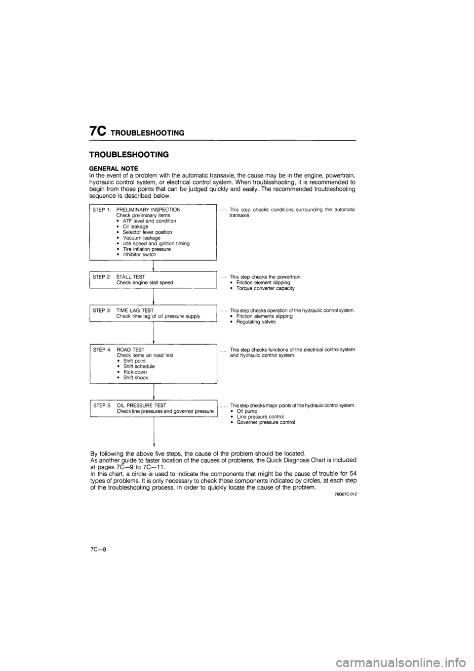
GENERAL NOTE
In the event of a problem with the automatic transaxle, the cause may be in the engine, powertrain,
hydraulic control system, or electrical control system. When troubleshooting, it is recommended to
begin from those points that can be judged quickly and easily. The recommended troubleshooting
sequence is described below.
STEP 1: PRELIMINARY INSPECTION Check preliminary items • ATF level and condition
• Oil leakage • Selector lever position
• Vacuum leakage
• Idle speed and ignition timing
• Tire inflation pressure • Inhibitor switch
This step checks conditions surrounding the automatic
transaxle.
STEP 2: STALL TEST Check engine stall speed This step checks the powertrain.
• Friction element slipping
• Torque converter capacity
STEP 3: TIME LAG TEST Check time lag of oil pressure supply This step checks operation of the hydraulic control system. • Friction elements slipping
• Regulating valves
STEP 4: ROAD TEST Check items on road test
• Shift point • Shift schedule
• Kick-down • Shift shock
This step checks functions of the electrical control system
and hydraulic control system.
STEP 5: OIL PRESSURE TEST Check line pressures and governor pressure This step checks major points of the hydraulic control system.
• Oil pump • Line pressure control • Governer pressure control
By following the above five steps, the cause of the problem should be located.
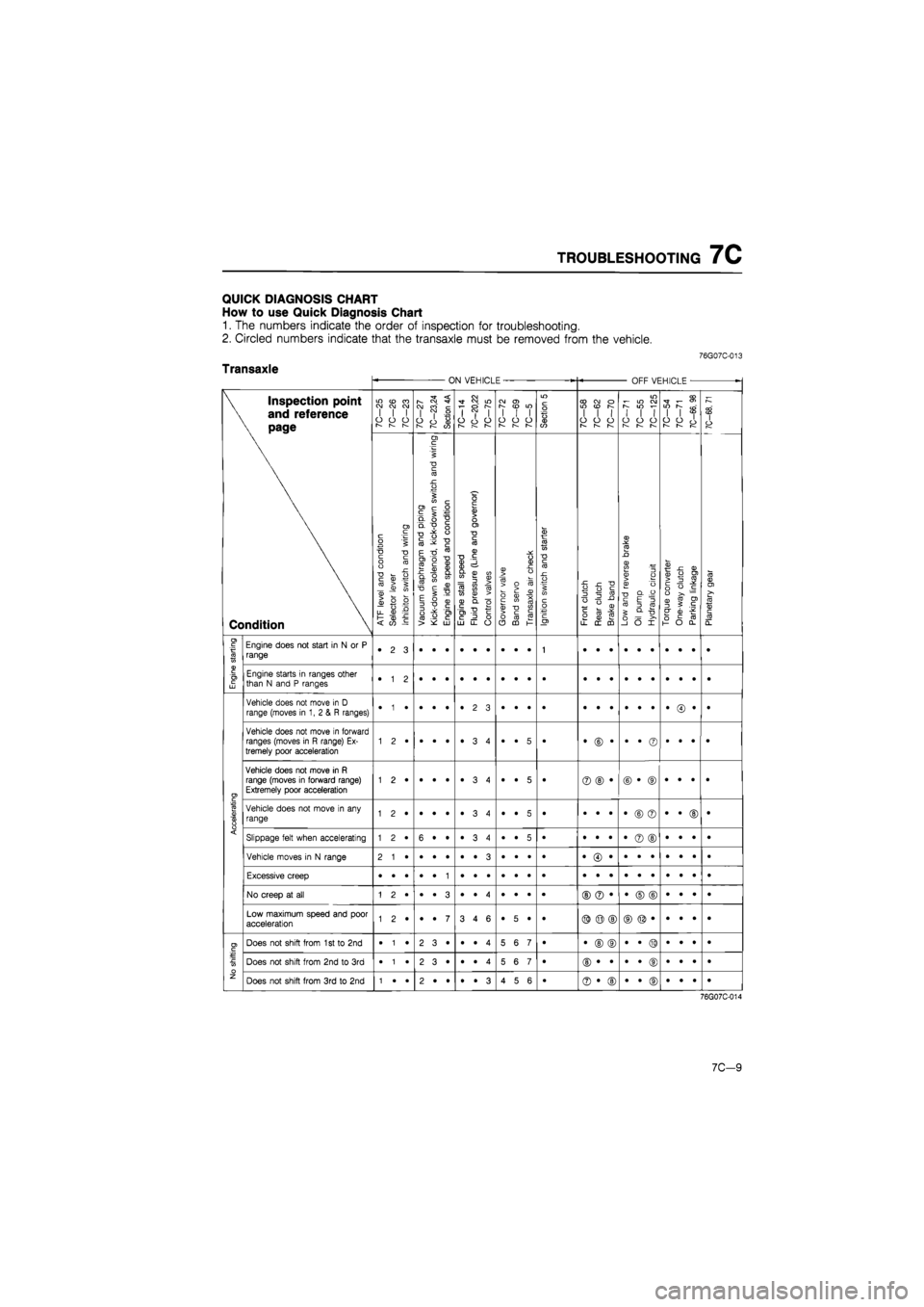
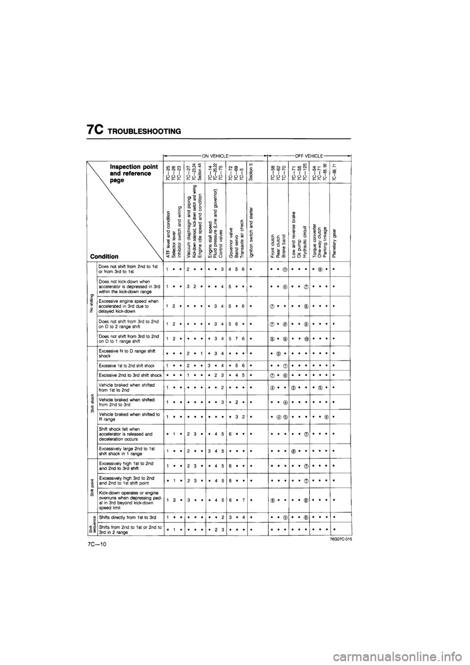
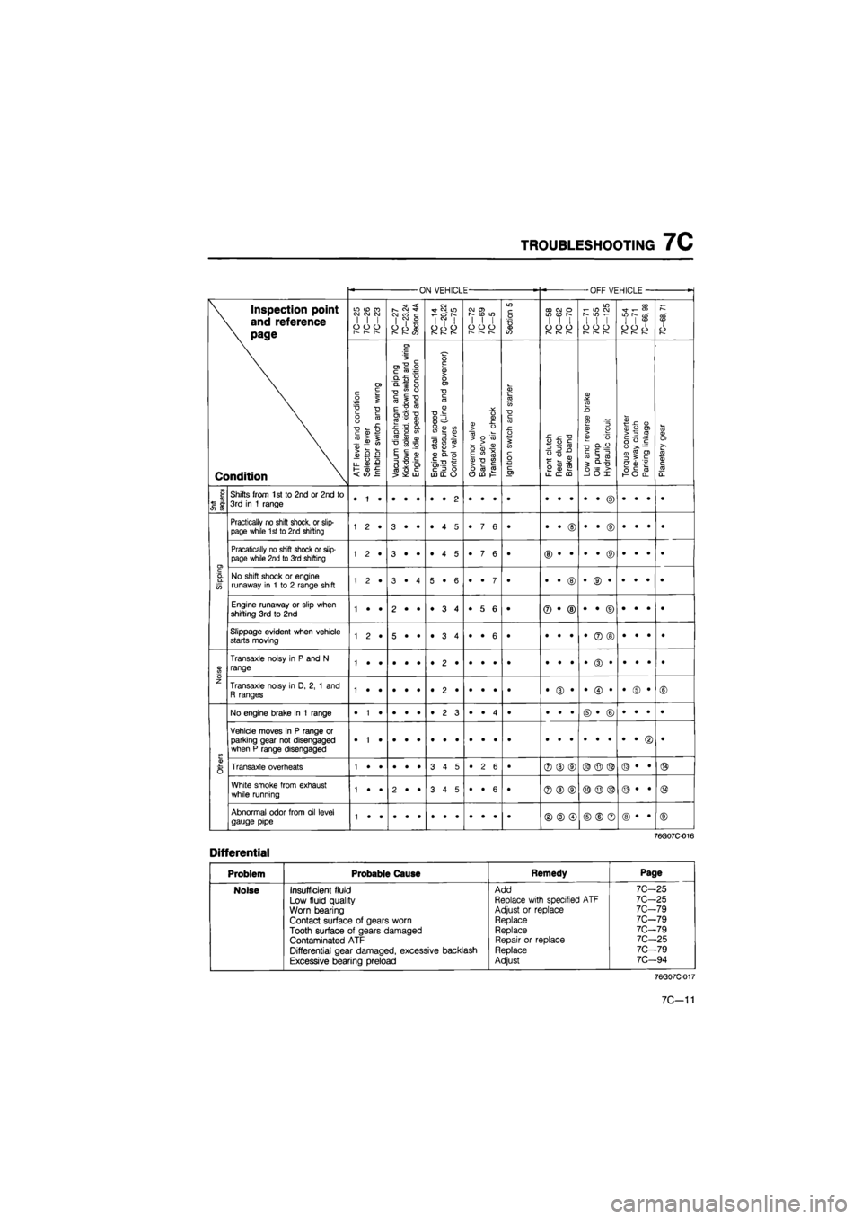
As another guide to faster location of the causes of problems, the Quick Diagnosis Chart is included
at pages 7C—9 to 7C—11.
In this chart, a circle is used to indicate the components that might be the cause of trouble for 54
types of problems. It is only necessary to check those components indicated by circles, at each step
of the troubleshooting process, in order to quickly locate the cause of the problem.
76G07C-012
7C—8
Page 1123 of 1865

TROUBLESHOOTING
7C
QUICK DIAGNOSIS CHART
How
to use
Quick Diagnosis Chart
1.
The
numbers indicate
the
order
of
inspection
for
troubleshooting.
2. Circled numbers indicate that
the
transaxle must
be
removed from
the
vehicle.
76G07C-013
Transaxle ON VEHICLE OFF VEHICLE
•
\ Inspection point
\
and
reference
\ page
Condition
7C-25
7C-26
7C-23
10—21
7C—23,24
Section
4A
7C-14
7C—20,22
10—lb
10-12 10—69
7C—5
Section
5
7C—58
7C-62
7C-70
7C-71
7C-55
7C-125
7C-54 7C-71
7C-66,
98
7C-68,
71
\ Inspection point
\
and
reference
\ page
Condition
ATF
level
and
condition
Selector
lever
Inhibitor
switch
and
wiring
^
Vacuum
diaphragm
and
piping
|
Kick-down
solenoid,
kick-down
switch
and
wiring
Engine
idle
speed
and
condition
Engine
stall
speed
Fluid
pressure
(Line
and
governor)
Control
valves
Governor
valve
Band
servo
Transaxle
air
check
Ignition
switch
and
starter
Front
clutch
Rear
clutch
Brake
band
Low
and
reverse
brake
Oil
pump Hydraulic
circuit
Torque
converter
One-way
clutch
Parking
linkage
Planetary
gear
I
Engine
starting
Engine does
not
start
in
N or P
range •
2 3
1
Engine
starting
Engine starts
in
ranges other than
N
and P
ranges •
1 2
Accelerating
Vehicle does
not
move
in
D
range (moves
in 1, 2 & R
ranges) •
• •
•
Accelerating
Vehicle does
not
move
in
forward ranges (moves
in R
range)
Ex-
tremely poor acceleration •
• 5
• •
© •
•
• ©
•
• •
•
Accelerating
Vehicle does
not
move
in R
range (moves
in
forward range) Extremely poor acceleration 1
2 •
•
• •
•
3 4
•
• 5
• ©
© •
©
• ©
•
• •
•
Accelerating
Vehicle does
not
move
in any
range 1
2 •
•
• •
•
3 4
•
• 5
• •
• •
•
© ©
•
• ©
•
Accelerating Slippage felt when accelerating 1
2 •
6
• •
•ST
CO
•
•
• 5
• •
• •
•
© ©
•
• •
• Accelerating
Vehicle moves
in
N
range
Accelerating
Excessive creep
Accelerating
No creep
at all
©
© •
•
© ©
•
• •
•
Accelerating
Low maximum speed
and
poor acceleration 1
2 •
•
• 7
3
4 6
•
5 •
• ©
© ©
No shifting
Does
not
shift from
1
st to 2nd
•
1 •
2
3 •
•
• 4
5
6 7
• •
© ©
•
• ©
•
• •
•
No shifting
Does
not
shift from
2nd to 3rd
•
1 •
2
3 •
•
• 4
5
6 7
•
No shifting
Does
not
shift from
3rd to 2nd
1
• •
2
• •
•
• 3
4
5 6
• ©
• ©
•
• ©
•
• •
•
76G07C-014
7C-9
Page 1124 of 1865

7C TROUBLESHOOTING
ON VEHICLE OFF VEHICLE
-
\ Inspection point
\ and reference
\ page
Condition
LO
(O
CO CJ OJ CM I
I I
O
O
CJ
r-~
r—
7C-27
7C—23,24
Section
4A
7C—14
7C—20,22
7C-75
CO
O)
I
I I
o
o o
r—
r—
Section
5
CO CO
o
WON I
I I
o
o o
1— 1—
m i-
in co
S
IO
i-
1
1 1
o
o o
—
I—
7C—54
7C-71
7C-66,
98
7C—68,
71
\ Inspection point
\ and reference
\ page
Condition
A.TF
level
and
condition
Selector
lever
Inhibitor
switch
and
wiring
Vacuum
diaphragm
and
piping
Kick-down
solenoid,
kick-down
switch
and
wiring
Engine
idle
speed
and
condition
Engine
stall
speed
Fluid
pressure
(Line
and
governor)
Control
valves
Governor
valve
Band
servo
Transaxle
air
check
Ignition
switch
and
starter
Front
clutch
Rear
clutch
Brake
band
Low
and
reverse
brake
Oil pump Hydraulic
circuit
Torque
converter
One-way
clutch
Parking
linkage
Planetary
gear
No
shifting
Does
not
shift from 2nd
to
1
st or from
3rd to
1
st 1
• •
2
• •
•
• 3
4
5 6
•
No
shifting
Does
not
kick-down when accelerator
is
depressed
in 3rd
within
the
kick-down range 1
• •
3
2*
•
• 4
5
• •
• •
• ©
•
• ©
•
• •
•
No
shifting
Excessive engine speed when accelerated
in 3rd
due
to
delayed kick-down 5
• 6
• ©
• •
•
• ©
•
• •
• No
shifting
Does
not
shift from
3rd to 2nd
on
D to
2
range shift 1
2 •
5
6 •
• ©
• ®
•
• ®
•
• •
•
No
shifting
Does
not
shift from
3rd to 2nd
on
D to 1
range shift 5
7 6
• ©
• ®
•
• ®
•
• •
•
Shift
shock
Excessive
N to
D
range shift shock •
• •
2
• 1
•
3 4
•
• •
• •
© •
•
• •
•
• •
•
Shift
shock
Excessive
1
st
to
2nd shift shock 1
• •
2
• •
3
• 4
•
5 6
• •
• ©
•
• •
•
• •
•
Shift
shock
Excissive 2nd
to 3rd
shift shock •
• •
1
• •
•
2 3
•
4 5
• ©
• ©
Shift
shock
Vehicle braked when shifted from
1
st
to 2nd
Shift
shock
Vehicle braked when shifted from 2nd
to 3rd
1
• •
•
• •
•
• 3
.
2 •
•
Shift
shock
Vehicle braked when shifted
to
R range 1
• •
•
• •
•
• •
•
3 2
• •
© ©
•
• •
•
• ©
•
Shift
shock
Shift shock felt when accelerator
is
released
and
deceleration occurs •
1 •
2
3*
•
4 5
6
• •
• •
• •
•
• ©
•
• *
•
Shift
shock
Excessively large 2nd
to 1st
shift shock
in 1
range 1
• •
2
• •
3
4 5
•
• •
•
Shift
point
Excessively high
1st to 2nd
and 2nd
to
3rd shift 1
• •
2
3 •
•
4 5
6
• •
•
Shift
point
Excessively high
3rd to 2nd
and
2nd to
1
st shift point •
1 •
2
3 •
•
4 5
6
• •
• •
• •
•
• ©
•
• •
•
Shift
point
Kick-down operates
or
engine overruns when depressing
ped-
al
in 3rd
beyond kick-down speed limit
1
2 •
3
• •
•
4 5
6
• 7
•
Shift
sequence
Shifts directly from 1st
to 3rd
1
• •
•
• •
•
• 2
3
• 4
• •
• ©
•
• ©
•
• •
•
Shift
sequence
Shifts from
2nd to 1st or
2nd
to
3rd
in
2
range •
1 •
•
• •
•
2 3
•
• •
•
7C-10
Page 1125 of 1865

TROUBLESHOOTING
7C
ON VEHICLE -OFF VEHICLE
-
\ Inspection point
\
and
reference
\ page
Condition
in cd
ra
CM CM CM
I
I I
o
o o
I—
r~—
r—
7C—27
7C—23,24
Section
4A
7C—14
7C—20,22
7C-75
CM
0>
[—
CO
LO I
I I
O
O O
r^ r—
Section
5
CD CM
O
in (D
s
I
I I
o
o o
r—
r^
w
CM
r-
m f-
I
I I
o
o o
r-— I—
r-—
7C—54
7C-71
7C—66,
98
7C-68,
71 \ Inspection point
\
and
reference
\ page
Condition
ATR
level
and
condition
Selector
lever
Inhibitor
switch
and
wiring
Vacuum
diaphragm
and
piping
Kick-down
solenoid,
kick-down
switch
and
wiring
Engine
idle
speed
and
condition
Engine
stall
speed
Fluid
pressure
(Line
and
governor)
Control
valves
Governor
valve
Band
servo
Transaxle
air
check
Ignition
switch
and
starter
Front
clutch
Rear
clutch
Brake
band
Low
and
reverse
brake
Oil
pump
Hydraulic
circuit
Torque
converter
One-way
clutch
Parking
linkage
Planetary
gear
Snift
sequence
Shifts from
1st to
2nd
or
2nd
to
3rd
in 1
range
Slipping
Practically
no
shift shock,
or
slip-page while 1st
to
2nd shifting 1
2 •
3
• •
•
4 5
•
7 6
• •
• ©
•
• ©
•
• •
•
Slipping
Pracatically
no
shift shock
or
slip-page while 2nd
to
3rd shifting 1
2 •
3
• •
•
4 5
•
7 6
•
Slipping
No shift shock
or
engine runaway
in 1 to 2
range shift 1
2 •
3
• 4
5
• 6
•
• 7
• •
• ©
•
© •
•
• •
•
Slipping
Engine runaway
or
slip when shifting
3rd to 2nd
1
• •
2
• •
•
3 4
•
5 6
• ®
• ©
•
• ®
•
• •
•
Slipping
Slippage evident when vehicle starts moving 1
2 •
5
• •
•
3 4
•
• 6
• •
• •
•
® ©
•
• •
•
Noise
Transaxle noisy
in P and N
range
Noise
Transaxle noisy
in D, 2, 1 and
R ranges •
(D •
•
© •
•
© •
©
Others
No engine brake
in 1
range •
1 •
•
• •
•
2 3
•
• 4
• •
• •
©
• ©
•
• •
•
Others
Vehicle moves
in P
range
or
parking gear
not
disengaged when
P
range disengaged
•
Others
Transaxle overheats 3
4 5
•
2 6
• ®
©
(D ©
© ©
©
• •
©
Others
White smoke from exhaust while running 1
• •
2
• •
3
4 5
•
• 6
• ®
© ©
©
© ©
©
• •
@
Others
Abnormal odor from
oil
level gauge pipe ©
® ©
©
© ®
©
• •
©
76G07C-016
Differential
Problem Probable Cause Remedy Page
Noise Insufficient fluid Add 7C—25
Low fluid quality Replace with specified
ATF
7C-25
Worn bearing Adjust
or
replace 7C-79
Contact surface
of
gears worn Replace 7C-79
Tooth surface
of
gears damaged Replace 7C-79
Contaminated
ATF
Repair
or
replace 7C-25
Differential gear damaged, excessive backlash Replace 7C-79
Excessive bearing preload Adjust 7C—94
76G07C-017
7C—11