Page 1908 of 2389
2. INSTALL PS BELT ADJUSTING BAR
3. (w/ A/C)
INSTALL A/C COMPRESSOR BRACKET
4. (w/ A/C)
INSTALL ALTERNATOR (Seepage CH±15)
5. (w/ A/C)
INSTALL A/C COMPRESSOR BRACKET
6. INSTALL CRANKSHAFT TIMING PULLEY, NO.1 IDLER
PULLEY AND TIMING BELT
(See pages EM±42 to 47)
7. REMOVE ENGINE HOIST CHAIN FROM ENGINE
8. INSTALL OIL PAN BAFFLE PLATE
(a) Remove any old packing (FIPG) material and be
careful not to drop any oil on the contact surfaces of
the baffle plate and cylinder block.
wUsing a razor blade and gasket scraper, remove
all the old packing (FIPG) material from the
gasket surfaces.
wThoroughly clean all components to remove all
the loose material.
wUsing a non±residue solvent, clean both sealing
surfaces.
NOTICE: Do not use a solvent which will affect the
painted surfaces.
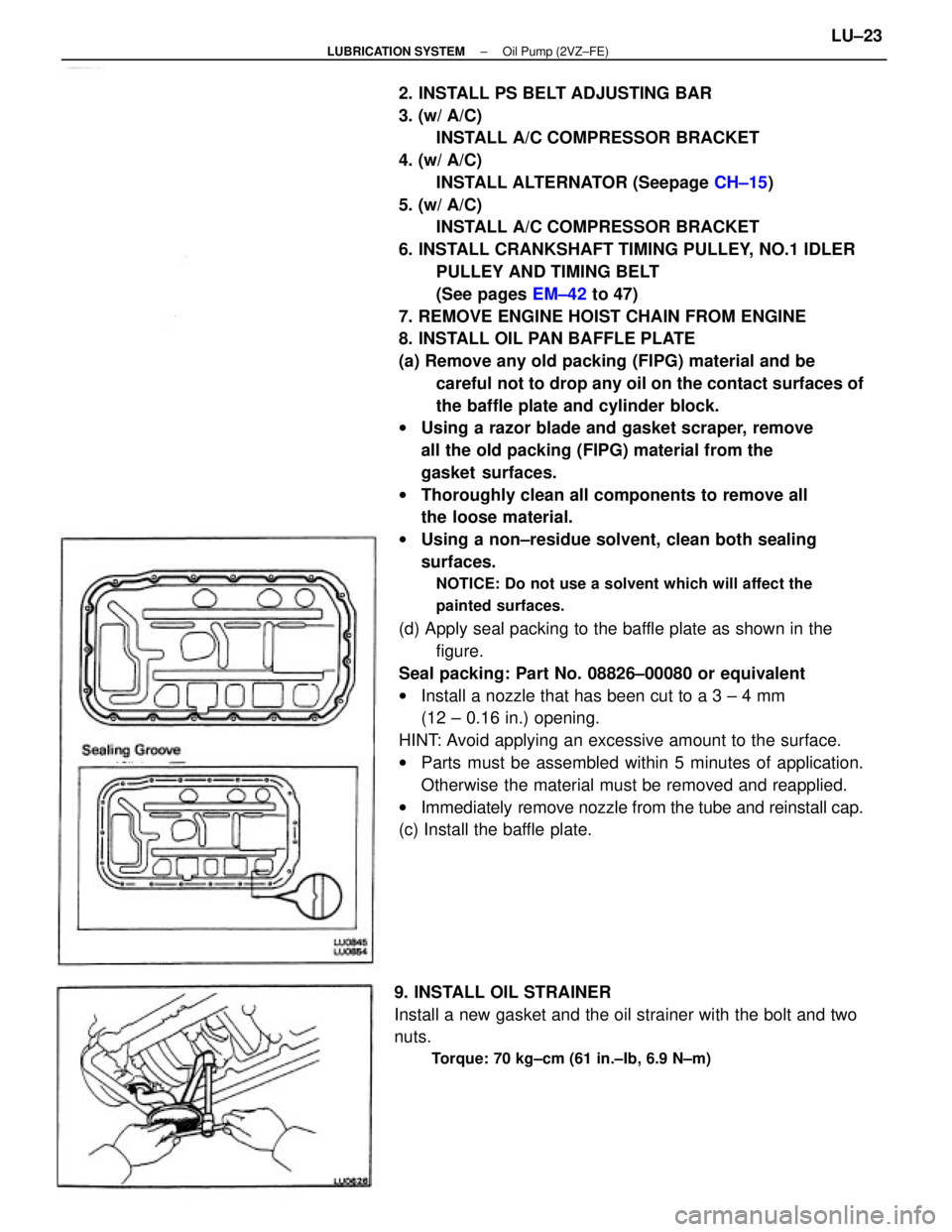
(d) Apply seal packing to the baffle plate as shown in the
figure.
Seal packing: Part No. 08826±00080 or equivalent
wInstall a nozzle that has been cut to a 3 ± 4 mm
(12 ± 0.16 in.) opening.
HINT: Avoid applying an excessive amount to the surface.
wParts must be assembled within 5 minutes of application.
Otherwise the material must be removed and reapplied.
wImmediately remove nozzle from the tube and reinstall cap.
(c) Install the baffle plate.
9. INSTALL OIL STRAINER
Install a new gasket and the oil strainer with the bolt and two
nuts.
Torque: 70 kg±cm (61 in.±Ib, 6.9 N±m)
± LUBRICATION SYSTEMOil Pump (2VZ±FE)LU±23
Page 1909 of 2389
10. INSTALL OIL PAN
(a) Remove any old packing (FIPG) material and be careful not
to drop any oil on the contact surfaces of the oil pan and
cylinder block.
wUsing a razor blade and gasket scraper, remove all the old
packing (F1PG) material from the gasket surfaces and seal-
ing groove.
wThoroughly clean all components to remove all the loose
material.
wUsing a non±residue solvent, clean both sealing surfaces.
NOTICE: Do not use a solvent which will affect the
painted surfaces.
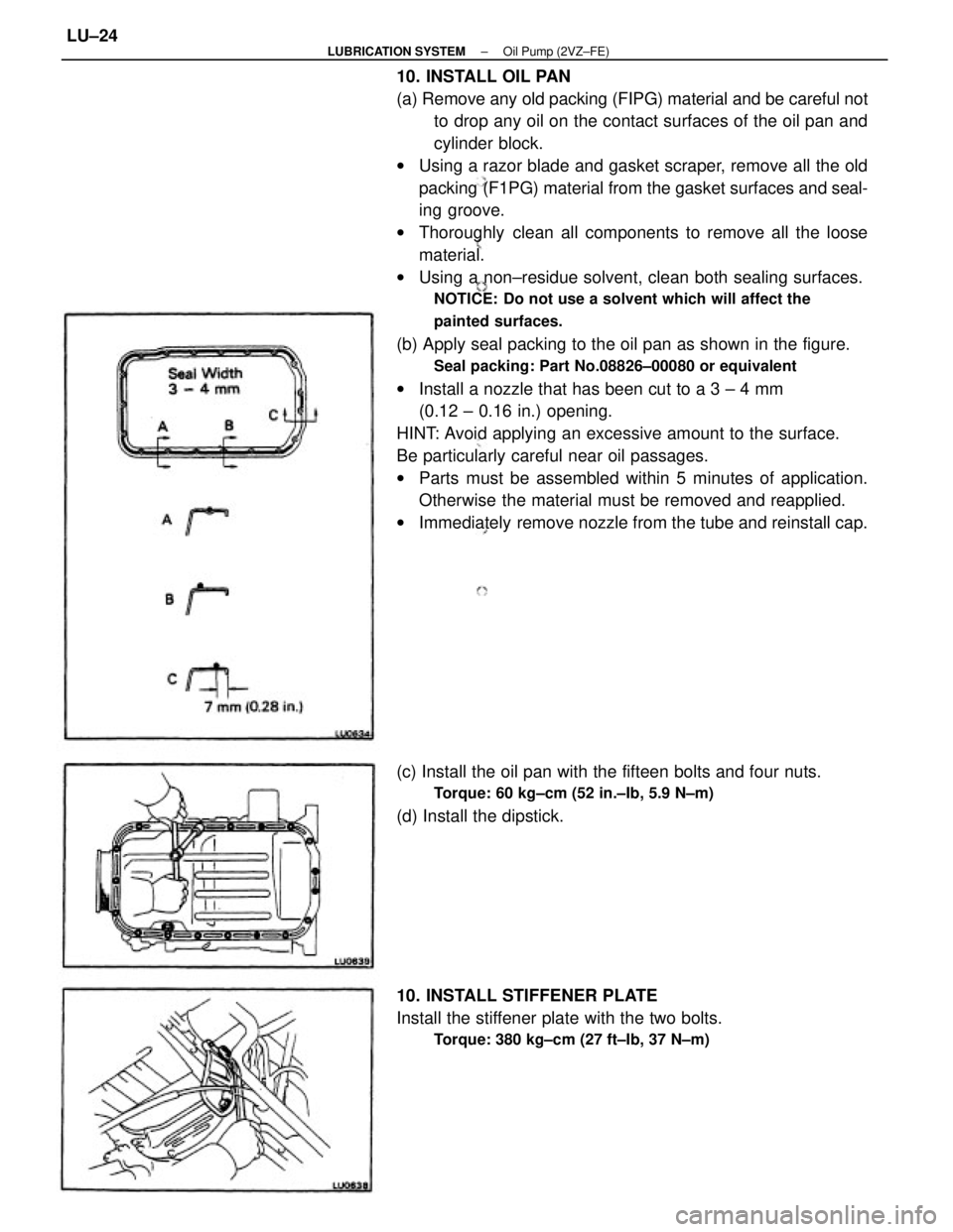
(b) Apply seal packing to the oil pan as shown in the figure.
Seal packing: Part No.08826±00080 or equivalent
wInstall a nozzle that has been cut to a 3 ± 4 mm
(0.12 ± 0.16 in.) opening.
HINT: Avoid applying an excessive amount to the surface.
Be particularly careful near oil passages.
wParts must be assembled within 5 minutes of application.
Otherwise the material must be removed and reapplied.
wImmediately remove nozzle from the tube and reinstall cap.
(c) Install the oil pan with the fifteen bolts and four nuts.
Torque: 60 kg±cm (52 in.±Ib, 5.9 N±m)
(d) Install the dipstick.
10. INSTALL STIFFENER PLATE
Install the stiffener plate with the two bolts.
Torque: 380 kg±cm (27 ft±Ib, 37 N±m)
± LUBRICATION SYSTEMOil Pump (2VZ±FE)LU±24
Page 1918 of 2389
6. REPLACE ENGINE OIL AND OIL FILTER
(See page LU±7)
Oil grade: API grade SG, multigrade, fuel±efficient and
recommended viscosity oil
Drain and refill with oil filter change capacity:
3.9 liters (4.1 US qts, 3.4 Imp. qts)
7. REPLACE ENGINE COOLANT
(See page CO±4)
Use a good brand of ethylene±glycol base coolant, mixed
according to the manufacturer's instructions.
Coolant capacity (w/ Heater):
3S±FE M/T 6.4 liters (6.8 US qts, 5.6 Imp. qts)
A/T (2WD)
6.3 liters (6.7 US qts, 5.5 Imp. qts)
A/T (4WD)
6.8 liters (7.2 US qts. 6.0 Imp. qts)
2VZ±FE M/T 9.5 liters (10.0 US qts, 8.4 Imp. qts)
A/T 9.4 liters (9.9 US qts, 8.3 Imp. qts)
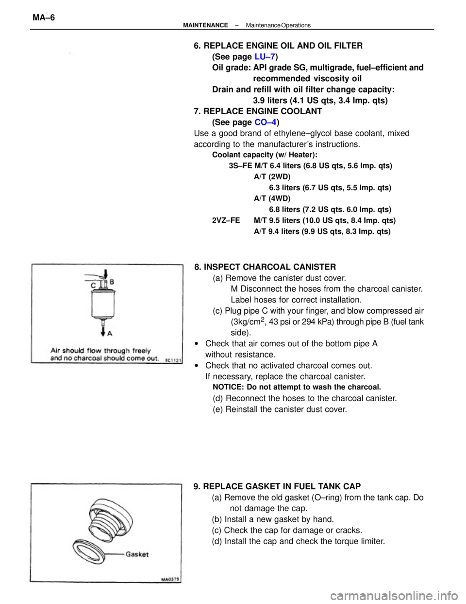
8. INSPECT CHARCOAL CANISTER
(a) Remove the canister dust cover.
M Disconnect the hoses from the charcoal canister.
Label hoses for correct installation.
(c) Plug pipe C with your finger, and blow compressed air
(3kg/cm
2, 43 psi or 294 kPa) through pipe B (fuel tank
side).
wCheck that air comes out of the bottom pipe A
without resistance.
wCheck that no activated charcoal comes out.
If necessary, replace the charcoal canister.
NOTICE: Do not attempt to wash the charcoal.
(d) Reconnect the hoses to the charcoal canister.
(e) Reinstall the canister dust cover.
9. REPLACE GASKET IN FUEL TANK CAP
(a) Remove the old gasket (O±ring) from the tank cap. Do
not damage the cap.
(b) Install a new gasket by hand.
(c) Check the cap for damage or cracks.
(d) Install the cap and check the torque limiter.
± MAINTENANCEMaintenance OperationsMA±6
Page 1926 of 2389
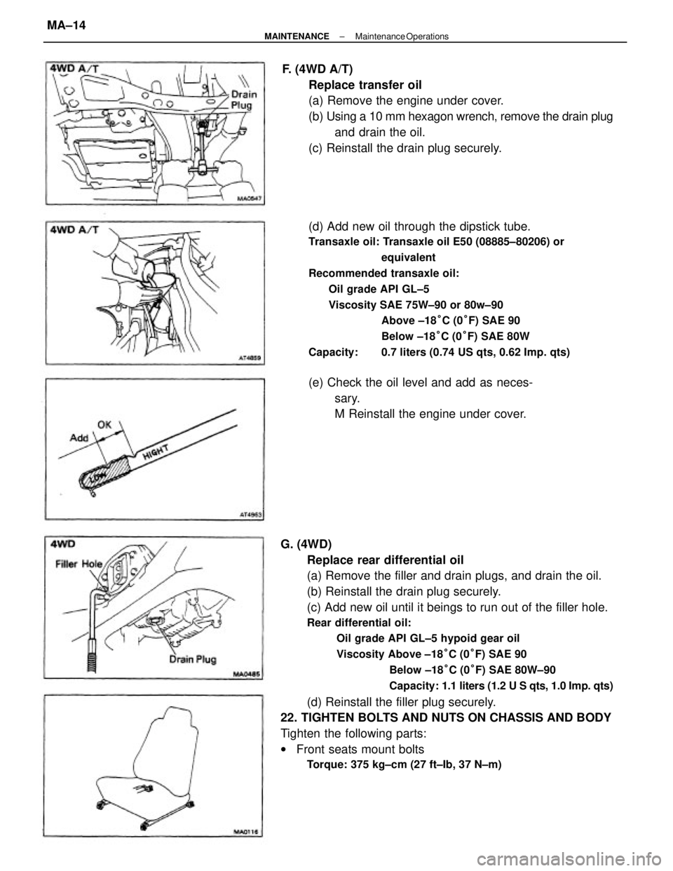
G. (4WD)
Replace rear differential oil
(a) Remove the filler and drain plugs, and drain the oil.
(b) Reinstall the drain plug securely.
(c) Add new oil until it beings to run out of the filler hole.
Rear differential oil:
Oil grade API GL±5 hypoid gear oil
Viscosity Above ±18°C (0°F) SAE 90
Below ±18°C (0°F) SAE 80W±90
Capacity: 1.1 liters (1.2 U S qts, 1.0 Imp. qts)
(d) Reinstall the filler plug securely.
22. TIGHTEN BOLTS AND NUTS ON CHASSIS AND BODY
Tighten the following parts:
wFront seats mount bolts
Torque: 375 kg±cm (27 ft±Ib, 37 N±m)
(d) Add new oil through the dipstick tube.
Transaxle oil: Transaxle oil E50 (08885±80206) or
equivalent
Recommended transaxle oil:
Oil grade API GL±5
Viscosity SAE 75W±90 or 80w±90
Above ±18°C (0°F) SAE 90
Below ±18°C (0°F) SAE 80W
Capacity: 0.7 liters (0.74 US qts, 0.62 Imp. qts)
F. (4WD A/T)
Replace transfer oil
(a) Remove the engine under cover.
(b) Using a 10 mm hexagon wrench, remove the drain plug
and drain the oil.
(c) Reinstall the drain plug securely.
(e) Check the oil level and add as neces-
sary.
M Reinstall the engine under cover.
± MAINTENANCEMaintenance OperationsMA±14
Page 1927 of 2389
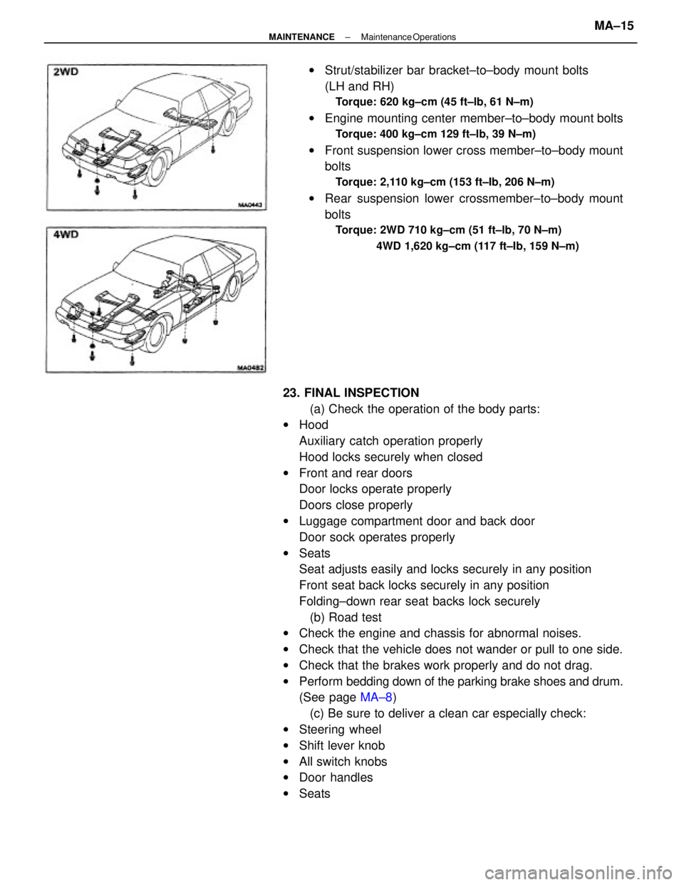
23. FINAL INSPECTION
(a) Check the operation of the body parts:
wHood
Auxiliary catch operation properly
Hood locks securely when closed
wFront and rear doors
Door locks operate properly
Doors close properly
wLuggage compartment door and back door
Door sock operates properly
wSeats
Seat adjusts easily and locks securely in any position
Front seat back locks securely in any position
Folding±down rear seat backs lock securely
(b) Road test
wCheck the engine and chassis for abnormal noises.
wCheck that the vehicle does not wander or pull to one side.
wCheck that the brakes work properly and do not drag.
wPerform bedding down of the parking brake shoes and drum.
(See page MA±8)
(c) Be sure to deliver a clean car especially check:
wSteering wheel
wShift lever knob
wAll switch knobs
wDoor handles
wSeatswStrut/stabilizer bar bracket±to±body mount bolts
(LH and RH)
Torque: 620 kg±cm (45 ft±lb, 61 N±m)
wEngine mounting center member±to±body mount bolts
Torque: 400 kg±cm 129 ft±lb, 39 N±m)
wFront suspension lower cross member±to±body mount
bolts
Torque: 2,110 kg±cm (153 ft±Ib, 206 N±m)
wRear suspension lower crossmember±to±body mount
bolts
Torque: 2WD 710 kg±cm (51 ft±lb, 70 N±m)
4WD 1,620 kg±cm (117 ft±Ib, 159 N±m)
± MAINTENANCEMaintenance OperationsMA±15
Page 1947 of 2389
5. MEASURE CLEARANCE OF SHIFT FORKS AND HUB
SLEEVES
Using a feeler gauge, measure the clearance between the
hub sleeve and shift fork.
Maximum clearance: 1.0 mm (0.039 in.)
If the clearance exceeds the limit, replace the shift fork or
hub sleeve.
(e) Using SST, press in a new bearing.
SST 09310±35010 .
(d) Install the transaxle case oil receiver and torque
the bolt.
Torque: 75 kg±cm (65 in.±Ib, 7.4 11f±m)
6. IF NECESSARY, REPLACE INPUT SHAFT FRONT
BEARING
(a) Remove the bolt and transaxle case oil receiver.
(b) Using SST, pull out the bearing.
SST 09308±00010 (b) Measure the clearance between the synchronizer ring
back and the gear spline end.
Minimum clearance: 0.6 mm 10.024 in.)
If the clearance is less than the limit, replace the synchro-
nizer ring. 4. INSPECT SYNCHRONIZER RINGS
(a) Turn the ring and push it in to check the braking action.
± MANUAL TRANSAXLES51 TransmissionMT±19
Page 1948 of 2389
7. IF NECESSARY, REPLACE OUTPUT SHAFT FRONT
BEARING
(a) Remove the bolt and bearing lock plate.
(b) Using SST, pull out the bearing.
SST 09308±00010
(b) Using SST, drive in a new oil seal.
SST 09608±20012 (09608±00080, 09608±03020)
Drive in depth: 1.0 ± 2.0 mm (0.039 ± 0.079 in.)
(c) Coat the lip of the oil seal with MP grease. (c) Using SST, press in a new bearing.
SST 09310±35010
(d) Install the bearing lock plate and torque the
bolt.
Torque: 185 kg±cm (13 ft±Ib, 18 N±m)
9. IF NECESSARY, REPLACE LH SIDE OIL SEAL
(a) Using SST, press out the oil seal from the retainer.
SST 09608±20012 (09608±00030,09608±03020) 8. IF NECESSARY, REPLACE INPUT SHAFT FRONT OIL
SEAL
(a) Using a screwdriver, pry out the oil seal.
± MANUAL TRANSAXLES51 TransmissionMT±20
Page 1949 of 2389
11. IF NECESSARY, REPLACE LH OUTER RACE OF
SIDE BEARING
(a) Using SST, press out the outer race.
SST 09608±20012 (09608±00060,09608±03020)
(b) Install the bearing retainer without an O±ring.
(e) Install and torque the retainer bolts.
Torque: 185 kg±cm(13 ft±Ib, 18 N±m)
(d) Place the thinnest shim into the case.
(See table on page MT±28)
(e) Using SST, press in a new outer race.
SST 09608±20012 (09608±03020,09608±03060) (b) Using SST, drive in a new oil seal until its surface
is flush with the case surface.
SST 09316±60010 (09316±00010)
(e) Coat the lip of the oil seal with MP grease.(b) Using SST, press in a new oil seal until its surface
is flush with the case surface.
SST 09316±60010 (09316±00010)
(c) Coat the lip of the oil seal with IMP grease.
10. IF NECESSARY, REPLACE RH SIDE OIL SEAL
(a) Drive out the oil seal with a screwdriver.
± MANUAL TRANSAXLES51 TransmissionMT±21