Page 1850 of 2389
(b) Using a tinning light, check the ignition tinning.
Ignition timing: 10
°6TDC @ idle
(Transmission in N range)
(c) Loosen the two hold±down bolts, and adjust by turning
the distributor.
(d) Tighten the hold±down bolts, and recheck the ignition
timing.
Torque: 130 kg±cm (9 ft±Ib, 13 N±m)
9. ADJUST IGNITION TIMING
(a) Using SST connect terminals TE1 and E1 of the check
connector.
SST 09843±18020
HINT: After engine rpm are kept at 1, 1,300 rpm for 5 sec-
onds, check that they return to. idle speed.
10. FURTHER CHECK IGNITION TIMING
Ignition timing: 13 ± 22
° BTDC @ idle
(Transmission in N range)
HINT: The timing mark moves in a range between 13°
and 22°.
11. DISCONNECT TACHOMETER AND TIMING LIGHT
FROM ENGINE (e) Remove SST.
SST 09843±18020
± IGNITION SYSTEMDistributor (3S±FE)IG±17
Page 1854 of 2389
![TOYOTA CAMRY V20 1986 Service Information 6. WARM UP ENGINE
Allow the engine to normal operating temperature.
7. CONNECT TACHOMETER AND TIMING LIGHT TO
ENGINE
Connect the tachometer test probe to terminal IG [±] of the
check connector.
NOTIC TOYOTA CAMRY V20 1986 Service Information 6. WARM UP ENGINE
Allow the engine to normal operating temperature.
7. CONNECT TACHOMETER AND TIMING LIGHT TO
ENGINE
Connect the tachometer test probe to terminal IG [±] of the
check connector.
NOTIC](/manual-img/14/57449/w960_57449-1853.png)
6. WARM UP ENGINE
Allow the engine to normal operating temperature.
7. CONNECT TACHOMETER AND TIMING LIGHT TO
ENGINE
Connect the tachometer test probe to terminal IG [±] of the
check connector.
NOTICE:
wNEVER allow the tachometer test probe to touch ground
as it could result in damage to the igniter
and/or ignition coil.
wAs some tachometers are not compatible with this igni-
tion system, we recommended that you confirm the
compatibility of your unit before use.
8. ADJUST IGNITION TIMING
(a) Check the idle speed.
Idle speed: 700
+ 50 rpm
(b) Using SST connect terminals TE1 and E1 of the check con-
nector.
SST 09843±18020
(c) Using a timing light, check the ignition timing.
Ignition timing: 10°6TDC @ idle
(Transmission in N range)
(d) Loosen the two hold±down bolts, and adjust by turning the
distributor.
(e) Tighten the hold±down bolts, and recheck the ignition timing.
Torque: 185 kg±cm (13 ft±Ib, 18 N±m)
9. FURTHER CHECK IGNITION TIMING
Ignition timing: 10°BTDC @ idle
(Transmission in N range)
HINT: The timing mark moves in a range between 13°
and 27°.
10. DISCONNECT TACHOMETER AND TIMING LIGHT
FROM ENGINE (f) Remove SST.
SST 09843±18020
± IGNITION SYSTEMDistributor (2VZ±FE)IG±21
Page 1860 of 2389

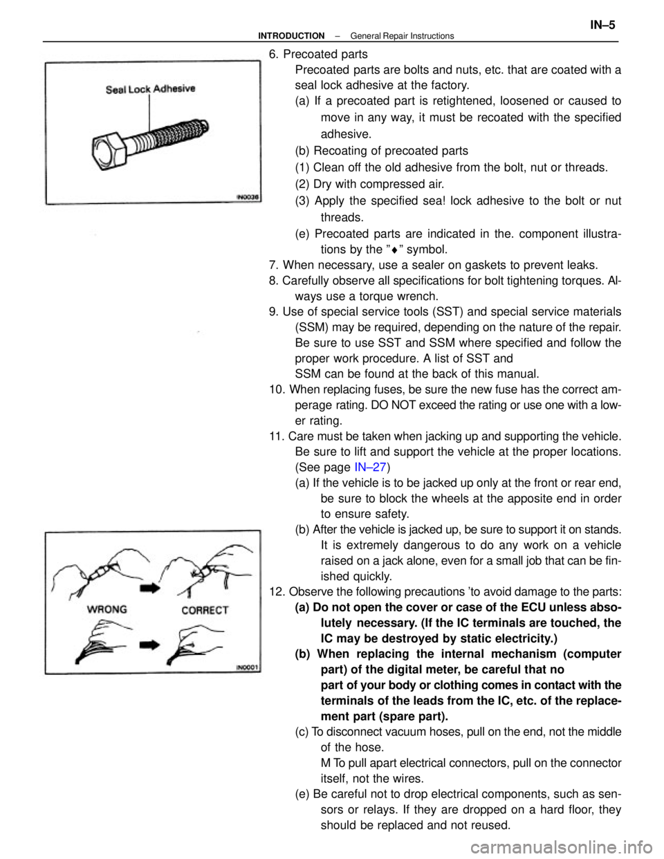
6. Precoated parts
Precoated parts are bolts and nuts, etc. that are coated with a
seal lock adhesive at the factory.
(a) If a precoated part is retightened, loosened or caused to
move in any way, it must be recoated with the specified
adhesive.
(b) Recoating of precoated parts
(1) Clean off the old adhesive from the bolt, nut or threads.
(2) Dry with compressed air.
(3) Apply the specified sea! lock adhesive to the bolt or nut
threads.
(e) Precoated parts are indicated in the. component illustra-
tions by the ºrº symbol.
7. When necessary, use a sealer on gaskets to prevent leaks.
8. Carefully observe all specifications for bolt tightening torques. Al-
ways use a torque wrench.
9. Use of special service tools (SST) and special service materials
(SSM) may be required, depending on the nature of the repair.
Be sure to use SST and SSM where specified and follow the
proper work procedure. A list of SST and
SSM can be found at the back of this manual.
10. When replacing fuses, be sure the new fuse has the correct am-
perage rating. DO NOT exceed the rating or use one with a low-
er rating.
11. Care must be taken when jacking up and supporting the vehicle.
Be sure to lift and support the vehicle at the proper locations.
(See page IN±27)
(a) If the vehicle is to be jacked up only at the front or rear end,
be sure to block the wheels at the apposite end in order
to ensure safety.
(b) After the vehicle is jacked up, be sure to support it on stands.
It is extremely dangerous to do any work on a vehicle
raised on a jack alone, even for a small job that can be fin-
ished quickly.
12. Observe the following precautions 'to avoid damage to the parts:
(a) Do not open the cover or case of the ECU unless abso-
lutely necessary. (If the IC terminals are touched, the
IC may be destroyed by static electricity.)
(b) When replacing the internal mechanism (computer
part) of the digital meter, be careful that no
part of your body or clothing comes in contact with the
terminals of the leads from the IC, etc. of the replace-
ment part (spare part).
(c) To disconnect vacuum hoses, pull on the end, not the middle
of the hose.
M To pull apart electrical connectors, pull on the connector
itself, not the wires.
(e) Be careful not to drop electrical components, such as sen-
sors or relays. If they are dropped on a hard floor, they
should be replaced and not reused.
± INTRODUCTIONGeneral Repair InstructionsIN±5
Page 1893 of 2389

3. FILL WITH ENGINE OIL
(a) Clean and install the oil drain plug with a new gasket.
Torque: 2VZ±FE 3S±FE 400 kg±cm (29 ft±lb, 39 N±m)
(b) Fill with new engine oil (API grade SG muitigrade,
fuel±efficient and recommended viscosity oil).
Capacity (3S±FE):
Drain and refill
w/ Oil filter change
4.1 liters (4.3 U S qts, 3.6 Imp. qts)
w/o Oil filter change
3.7 liters (3.9 US qts, 3.3 Imp. qts)
Dry fill 4.5 liters (4.8 U S qts, 4.4 Imp. qts)
Capacity (2VZ±FE):
Drain and refill
w/ Oil filter change
3.9 liters (4.1 US qts, 3.4 Imp. qts)
w/o Oil filter change
3.7 liters (3.9 US qts, 3.3 Imp. qts)
Dry fill 4.6 liters (4.8 US qts, 4.4 Imp. qts)
(c) Install the oil filler cap.
4. START ENGINE AND CHECK FOR LEAKS
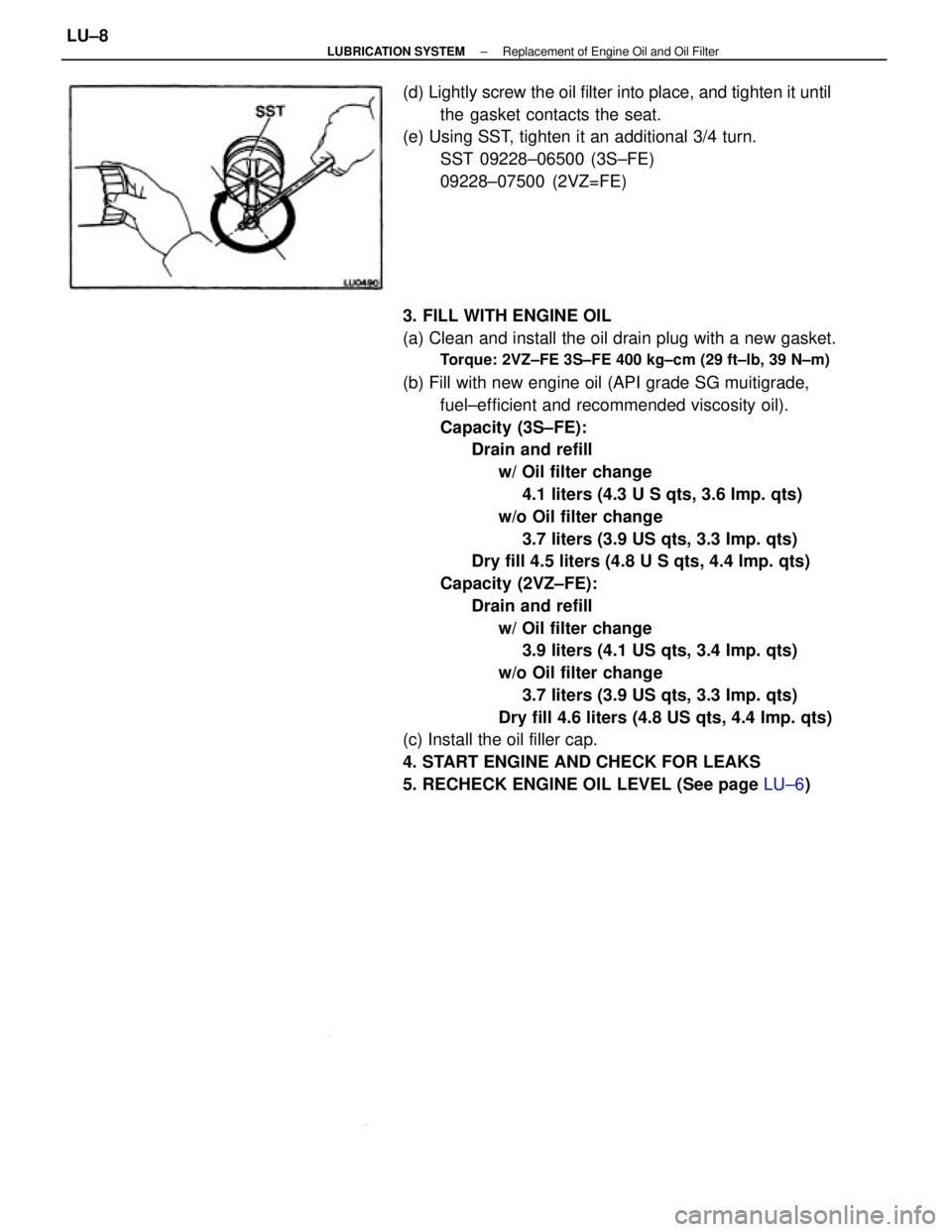
5. RECHECK ENGINE OIL LEVEL (See page LU±6) (d) Lightly screw the oil filter into place, and tighten it until
the gasket contacts the seat.
(e) Using SST, tighten it an additional 3/4 turn.
SST 09228±06500 (3S±FE)
09228±07500 (2VZ=FE)
± LUBRICATION SYSTEMReplacement of Engine Oil and Oil FilterLU±8
Page 1898 of 2389
2. INSTALL OIL SEAL
(a) Using SST and a hammer, tap in a new oil sea! to a depth
of approx.1 mm (0.04 in.) from the oil pump cover
edge.
SST 09620±30010 (09627±30010, 09631 ± 20)
(b) Apply MP grease to the oil seal lip.
ASSEMBLY OF OIL PUMP
(See page LU±11)
1. INSTALL DRIVE AND DRIVEN ROTORS
(a) Place a new 0±ring into the pump body groove.
(b) Place the drive and driven rotors into pump body.
2. INSTALL RELIEF VALVE
(a) Insert the relief valve, spring and retainer into the pump body
hole.
(b) Using snap ring pliers, install the snap ring.
REPLACEMENT OF OIL SEAL
1. REMOVE OIL SEAL
Using a screwdriver, pry out the oil seal.
(c) Install the pump body cover with the two bolts.
Torque: 90 kg±cm (78 in.±1b. 8.8 N±m)
± LUBRICATION SYSTEMOil Pump (3S±FE)LU±13
Page 1899 of 2389

5. INSTALL OIL PAN
(a) Remove any old packing (FIPG) material and be careful not
to drop any oil on the contact surfaces of the oil pan
and cylinder block.
wUsing a razor blade and gasket scraper, remove all the old
packing (FlPG) material from the gasket surfaces and seal-
ing groove.
wThoroughly clean all components to remove all the
loose material.
wUsing a non±residue solvent, clean both sealing surfaces.
NOTICE: Do not use a solvent which will affect the painted
surfaces.
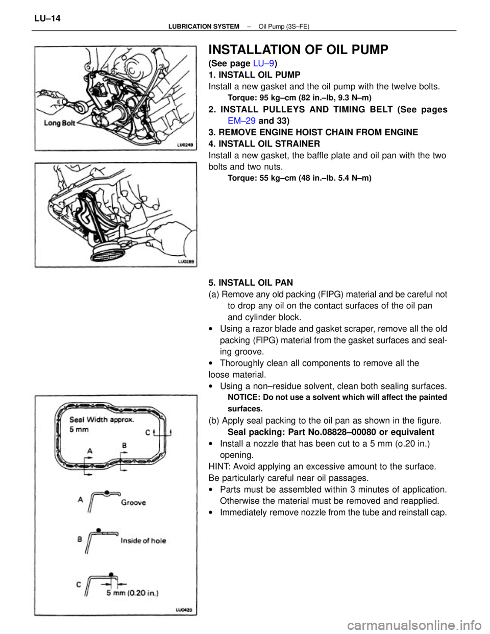
(b) Apply seal packing to the oil pan as shown in the figure.
Seal packing: Part No.08828±00080 or equivalent
wInstall a nozzle that has been cut to a 5 mm (o.20 in.)
opening.
HINT: Avoid applying an excessive amount to the surface.
Be particularly careful near oil passages.
wParts must be assembled within 3 minutes of application.
Otherwise the material must be removed and reapplied.
wImmediately remove nozzle from the tube and reinstall cap.
INSTALLATION OF OIL PUMP
(See page LU±9)
1. INSTALL OIL PUMP
Install a new gasket and the oil pump with the twelve bolts.
Torque: 95 kg±cm (82 in.±Ib, 9.3 N±m)
2. INSTALL PULLEYS AND TIMING BELT (See pages
EM±29 and 33)
3. REMOVE ENGINE HOIST CHAIN FROM ENGINE
4. INSTALL OIL STRAINER
Install a new gasket, the baffle plate and oil pan with the two
bolts and two nuts.
Torque: 55 kg±cm (48 in.±Ib. 5.4 N±m)
± LUBRICATION SYSTEMOil Pump (3S±FE)LU±14
Page 1900 of 2389
9. INSTALL FRONT EXHAUST PIPE
(See step 12 on page EM±134)
10. INSTALL ENGINE UNDER COVERS
11. LOWER VEHICLE
12. FILL WITH ENGINE OIL (See page LU±8)
13. START ENGINE AND CHECK FOR LEAKS
14. RECHECK ENGINE OIL LEVEL (See page LU±6)
15. INSTALL HOOD8. INSTALL SUSPENSION LOWER CROSSMEMBER
Torque:
14 mm head bolt
400 kg±cm (32 ft±lb, 43 N±m)
19 mm head bolt
2,120 kg±cm (153 ft±Ib, 208 N±m)
7. INSTALL ENGINE MOUNTING CENTER MEMBER
Torque:
To body 400 kg±cm (29 ft±lb, 39 N±m)
To mounting insulator
490 kg±cm (35 ft±tb, 48 N±m)
(c) Install the oil pan with the seventeen bolts and two
nuts.
Torque: 55 kg±cm (48 in.±Ib. 5.4 N±m)
(d) Install the dipstick.
6. INSTALL STIFFENER PLATE
Torque: 380 kg±cm (27±Ib, 37 N±m)
± LUBRICATION SYSTEMOil Pump (3S±FE)LU±15
Page 1907 of 2389

INSTALLATION OF OIL. PUMP
(See page LU±16)
1. INSTALL OIL PUMP
(a) Remove any old packing (FIPG) material and be careful not
to drop any oil on the contact surfaces of the oil pump and
cylinder block.
wUsing a razor blade and gasket scraper, remove all the old
packing (FIPG) material from the gasket surfaces and seal-
ing groove.
wThoroughly clean all components to remove all the loose
material.
wUsing a non±residue solvent, clean both sealing surfaces.
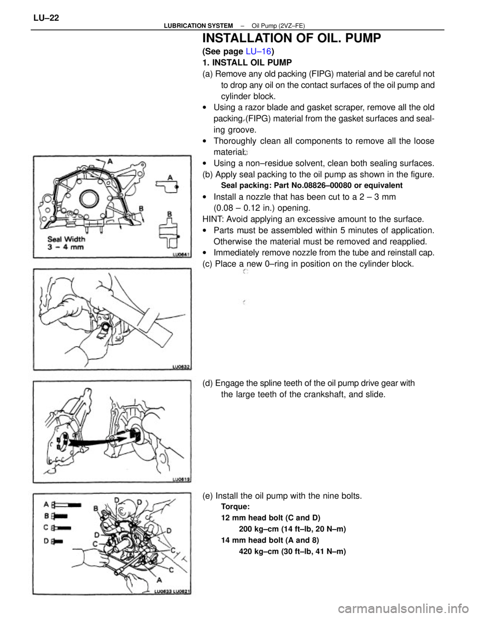
(b) Apply seal packing to the oil pump as shown in the figure.
Seal packing: Part No.08826±00080 or equivalent
wInstall a nozzle that has been cut to a 2 ± 3 mm
(0.08 ± 0.12 in.) opening.
HINT: Avoid applying an excessive amount to the surface.
wParts must be assembled within 5 minutes of application.
Otherwise the material must be removed and reapplied.
wImmediately remove nozzle from the tube and reinstall cap.
(c) Place a new 0±ring in position on the cylinder block.
(e) Install the oil pump with the nine bolts.
Torque:
12 mm head bolt (C and D)
200 kg±cm (14 ft±lb, 20 N±m)
14 mm head bolt (A and 8)
420 kg±cm (30 ft±lb, 41 N±m)
(d) Engage the spline teeth of the oil pump drive gear with
the large teeth of the crankshaft, and slide.
± LUBRICATION SYSTEMOil Pump (2VZ±FE)LU±22