Page 1345 of 2389
4. INSTALL OIL FILTER (See page LU±7)
5. INSTALL OIL PUMP AND OIL PAN
(See page LU±14)
6. INSTALL WATER PUMP (See page CO±6)
7. INSTALL CYLINDER HEADS
(See pages EM±96 to 106)
8. INSTALL PULLEYS AND TIMING BELT
(See pages EM±42 to 47)
9. INSTALL DISTRIBUTOR (See page IG±19)
10. REMOVE ENGINE STAND
11. INSTALL REAR END PLATE
Install the end plate with the bolt.
Torque: 75 kg±cm (65 in.±Ib, 7.4 N±m)
12. (M/T)
INSTALL FLYWHEEL
(a) Apply adhesive to two or three threads of the mount bolt
end.
Adhesive: Part No. 08833±00070, THREE BOND
1324 or equivalent
13. (A/T)
INSTALL DRIVE PLATE (See procedure step 12)
Torque: 854 kg±cm (61 ft±Ib, 83 N±m)
14. (M/T)
INSTALL CLUTCH DISC AND COVER (b) Install the flywheel on the crankshaft.
(c) Install and uniformly tighten the eight mount bolts in
several passes, in the sequence shown.
Torque: 850 kg±cm (61 ft±Ib, 83 N±m)
± ENGINE MECHANICALCylinder Block (2VZ±FE)EM±168
Page 1346 of 2389

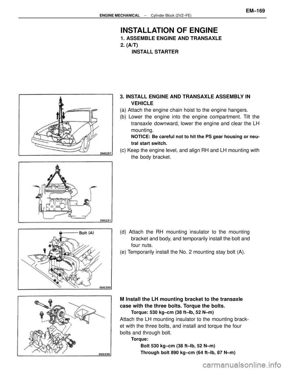
3. INSTALL ENGINE AND TRANSAXLE ASSEMBLY IN
VEHICLE
(a) Attach the engine chain hoist to the engine hangers.
(b) Lower the engine into the engine compartment. Tilt the
transaxle downward, lower the engine and clear the LH
mounting.
NOTICE: Be careful not to hit the PS gear housing or neu-
tral start switch.
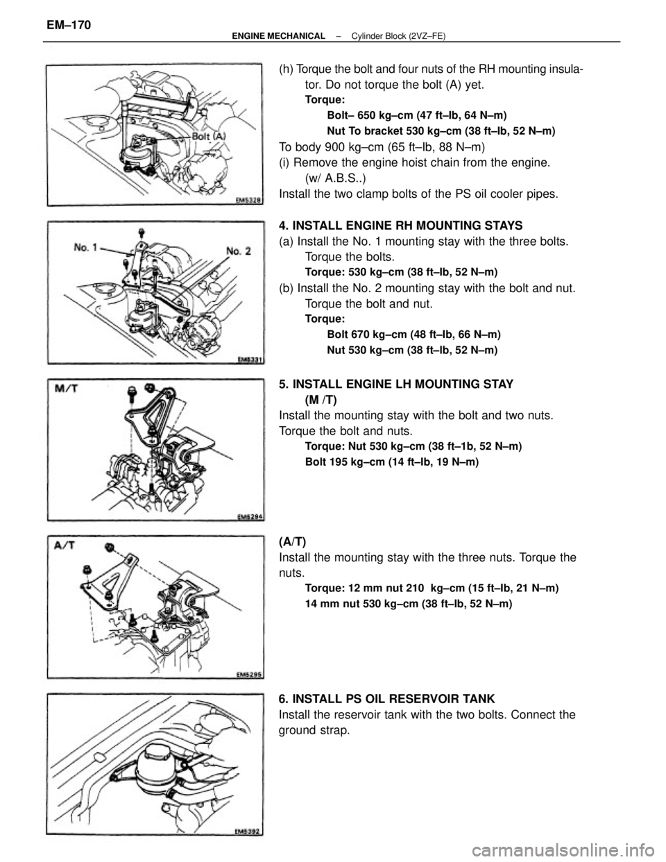
(c) Keep the engine level, and align RH and LH mounting with
the body bracket.
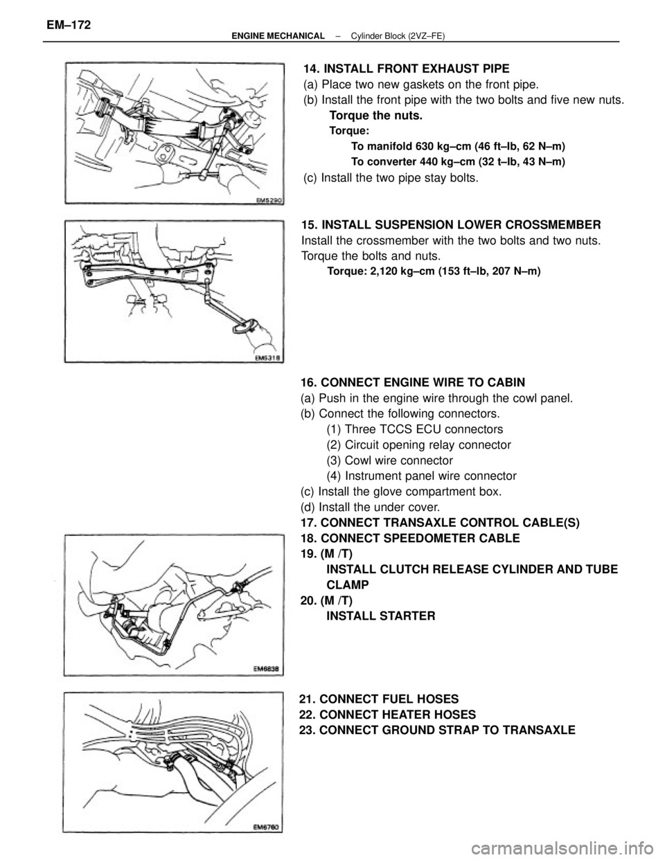
M Install the LH mounting bracket to the transaxle
case with the three bolts. Torque the bolts.
Torque: 530 kg±cm (38 ft±Ib, 52 N±m)
Attach the LH mounting insulator to the mounting brack-
et with the three bolts, and install and torque the four
bolts and through bolt.
Torque:
Bolt 530 kg±cm (38 ft±Ib, 52 N±m)
Through bolt 890 kg±cm (64 ft±Ib, 87 N±m)
INSTALLATION OF ENGINE
1. ASSEMBLE ENGINE AND TRANSAXLE
2. (A/T)
INSTALL STARTER
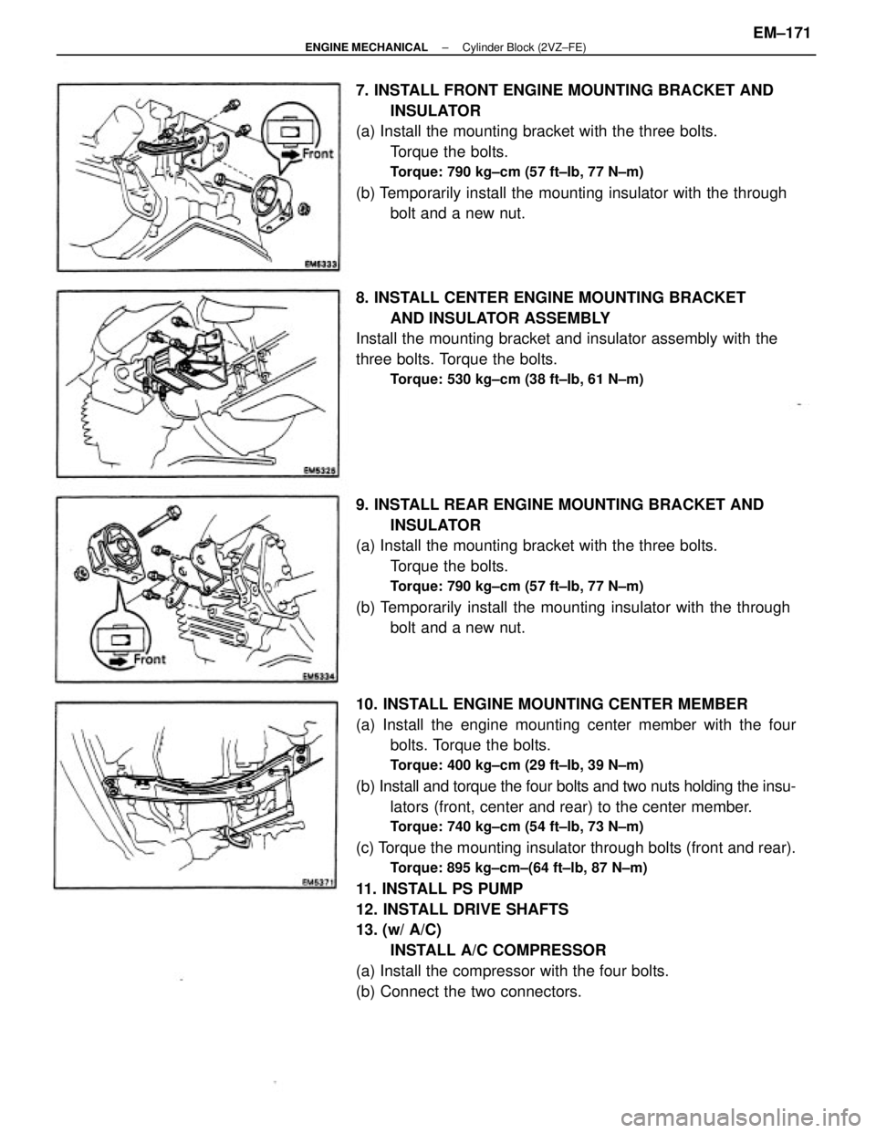
(d) Attach the RH mounting insulator to the mounting
bracket and body, and temporarily install the bolt and
four nuts.
(e) Temporarily install the No. 2 mounting stay bolt (A).
± ENGINE MECHANICALCylinder Block (2VZ±FE)EM±169
Page 1347 of 2389

4. INSTALL ENGINE RH MOUNTING STAYS
(a) Install the No. 1 mounting stay with the three bolts.
Torque the bolts.
Torque: 530 kg±cm (38 ft±Ib, 52 N±m)
(b) Install the No. 2 mounting stay with the bolt and nut.
Torque the bolt and nut.
Torque:
Bolt 670 kg±cm (48 ft±Ib, 66 N±m)
Nut 530 kg±cm (38 ft±lb, 52 N±m)
(h) Torque the bolt and four nuts of the RH mounting insula-
tor. Do not torque the bolt (A) yet.
Torque:
Bolt± 650 kg±cm (47 ft±Ib, 64 N±m)
Nut To bracket 530 kg±cm (38 ft±Ib, 52 N±m)
To body 900 kg±cm (65 ft±Ib, 88 N±m)
(i) Remove the engine hoist chain from the engine.
(w/ A.B.S..)
Install the two clamp bolts of the PS oil cooler pipes.
5. INSTALL ENGINE LH MOUNTING STAY
(M /T)
Install the mounting stay with the bolt and two nuts.
Torque the bolt and nuts.
Torque: Nut 530 kg±cm (38 ft±1b, 52 N±m)
Bolt 195 kg±cm (14 ft±Ib, 19 N±m)
(A/T)
Install the mounting stay with the three nuts. Torque the
nuts.
Torque: 12 mm nut 210 kg±cm (15 ft±Ib, 21 N±m)
14 mm nut 530 kg±cm (38 ft±Ib, 52 N±m)
6. INSTALL PS OIL RESERVOIR TANK
Install the reservoir tank with the two bolts. Connect the
ground strap.
± ENGINE MECHANICALCylinder Block (2VZ±FE)EM±170
Page 1348 of 2389

10. INSTALL ENGINE MOUNTING CENTER MEMBER
(a) Install the engine mounting center member with the four
bolts. Torque the bolts.
Torque: 400 kg±cm (29 ft±Ib, 39 N±m)
(b) Install and torque the four bolts and two nuts holding the insu-
lators (front, center and rear) to the center member.
Torque: 740 kg±cm (54 ft±lb, 73 N±m)
(c) Torque the mounting insulator through bolts (front and rear).
Torque: 895 kg±cm±(64 ft±lb, 87 N±m)
11. INSTALL PS PUMP
12. INSTALL DRIVE SHAFTS
13. (w/ A/C)
INSTALL A/C COMPRESSOR
(a) Install the compressor with the four bolts.
(b) Connect the two connectors. 7. INSTALL FRONT ENGINE MOUNTING BRACKET AND
INSULATOR
(a) Install the mounting bracket with the three bolts.
Torque the bolts.
Torque: 790 kg±cm (57 ft±Ib, 77 N±m)
(b) Temporarily install the mounting insulator with the through
bolt and a new nut.
9. INSTALL REAR ENGINE MOUNTING BRACKET AND
INSULATOR
(a) Install the mounting bracket with the three bolts.
Torque the bolts.
Torque: 790 kg±cm (57 ft±Ib, 77 N±m)
(b) Temporarily install the mounting insulator with the through
bolt and a new nut. 8. INSTALL CENTER ENGINE MOUNTING BRACKET
AND INSULATOR ASSEMBLY
Install the mounting bracket and insulator assembly with the
three bolts. Torque the bolts.
Torque: 530 kg±cm (38 ft±Ib, 61 N±m)
± ENGINE MECHANICALCylinder Block (2VZ±FE)EM±171
Page 1349 of 2389

16. CONNECT ENGINE WIRE TO CABIN
(a) Push in the engine wire through the cowl panel.
(b) Connect the following connectors.
(1) Three TCCS ECU connectors
(2) Circuit opening relay connector
(3) Cowl wire connector
(4) Instrument panel wire connector
(c) Install the glove compartment box.
(d) Install the under cover.
17. CONNECT TRANSAXLE CONTROL CABLE(S)
18. CONNECT SPEEDOMETER CABLE
19. (M /T)
INSTALL CLUTCH RELEASE CYLINDER AND TUBE
CLAMP
20. (M /T)
INSTALL STARTER 14. INSTALL FRONT EXHAUST PIPE
(a) Place two new gaskets on the front pipe.
(b) Install the front pipe with the two bolts and five new nuts.
Torque the nuts.
Torque:
To manifold 630 kg±cm (46 ft±Ib, 62 N±m)
To converter 440 kg±cm (32 t±Ib, 43 N±m)
(c) Install the two pipe stay bolts.
15. INSTALL SUSPENSION LOWER CROSSMEMBER
Install the crossmember with the two bolts and two nuts.
Torque the bolts and nuts.
Torque: 2,120 kg±cm (153 ft±lb, 207 N±m)
21. CONNECT FUEL HOSES
22. CONNECT HEATER HOSES
23. CONNECT GROUND STRAP TO TRANSAXLE
± ENGINE MECHANICALCylinder Block (2VZ±FE)EM±172
Page 1363 of 2389
HINT: Insure that the lengths of the left and right
tie rod ends length are the same.
Tie rod end length left±right error:
Less than 1.5 mm (0.059 in.)
(d) Torque the tie rod end lock nuts.
Torque: 570 kg±cm (41 ft±lb , 56 N±M)
(e) Place the boot on the seat and clamp it.
HINT: Insure that the boots are not twisted.(e) Turn the left and right tie rod ends an equal amount to
adjust the toe±in.
Adjustment standard: 1 + 1 mm (0.04 + 0.04 in.)
10. INSPECT SIDE SLIP (REFERENCE ONLY)
Side slip: Less than 3.0 mm/m (0.118 in./3.3 ft)
± FRONT AXLE AND SUSPENSIONFront Wheel AlignmentFA ± 6
Page 1369 of 2389
6. INSTALL INNER OIL SEAL
(a) Rotate and insert the side lip of a new oil seal into the
SST.
SST 09608±32010
(b) Using SST, install the oil seal into the steering knuckle.
SST 09608±32010 and 09710±14012 (09710±00050)
(c) Coat the oil seal lip with MP grease.
7. INSTALL DUST DEFLECTOR
Using SST, drive the dust deflector to the steering
knuckle.
SST 09608±35014 (09608±06020,09608±06180)
8. INSTALL BALL JOINT TO STEERING KNUCKLE
Torque: 1,150 kg±cm (83 ft±lb, 113 N±m)
± FRONT AXLE AND SUSPENSIONFront Axle HubFA±12
Page 1370 of 2389
2. CONNECT STEERING KNUCKLE TO SHOCK
ABSORBER
NOTICE: Apply engine oil to the threads of the two bolts.
(a) Connect the steering knuckle to the shock absorber
lower bracket.
(b) Insert the bolts and align the matchmarks of the camber
adjusting cam.
(c) Torque the nuts.
Torque: 3,100 kg±cm (224 ft±Ib, 304 N±m)
3. CONNECT TIE ROD END TO STEERING KNUCKLE
Torque the castle nut and secure it with a new cotter pin.
Torque: 500 kg±cm (36 ft±Ib, 49 N±m)
INSTALLATION OF FRONT AXLE HUB
(See page FA ± 7)
1. INSTALL STEERING KNUCKLE TO LOWER
SUSPENSION ARM
install the steering knuckle to the lower suspension arm,
and temporarily install the nut.
4. TORQUE BALL JOINT TO LOWER ARM
Install and torque the castle nut and secure it with a new
cotter pin.
Torque: 1,250 kg±cm (90 ft±lb, 123 N±m)
5. INSTALL ROTOR DISC TO AXLE HUB
6. INSTALL DISC BRAKE CALIPER TO STEERING
KNUCKLE
Torque: 1,190 kg±cm (86 ft±Ib, 117 N±m)
± FRONT AXLE AND SUSPENSIONFront Axle HubFA±13