Page 1292 of 2389
(i) Remove the connecting rod cap.
(j) Measure the Plastigage at widest point.
Standard oil clearance:
STD 0.024 ± 0.055 mm
(0.0009 ± 0.0022 in.)
U/S 0.25 0.023 ± 0.069 mm
(0.0009 ± 0.0027 in.)
Maximum oil clearance: 0.08 mm (0.0031 in.)
If the oil clearance is greater than maximum, replace
the bearings. If necessary, replace the crankshaft. (e) Clean crank pin and bearing.
(f) Check the crank pin and bearing for pitting and
scratches.
If the crank pin or bearing are damaged, replace the
bearings.
If necessary, replace the crankshaft.
(h) Install the connecting rod cap.
(See step 6 on page EM±129)
Torque: 500 kg±cm (36 ft±lb. 49 N±m)
HINT: Do not turn the crankshaft.(d) Cover the connecting rod bolts with a short piece of
hose to protect the crankshaft from damage.
(g) Lay a strip of Plastigage across the crank pin.
± ENGINE MECHANICALCylinder Block (3S±FE)EM±115
Page 1294 of 2389

(h) Install the main bearing caps.
(See step 4 on page EM±128)
Torque: 600 kg±cm (43 ft±tb, 59 N±m)
HINT: Do not turn the crankshaft
(i) Remove the main bearing caps.
(j) Measure the Plastigage at its widest point.
Standard oil clearance:
No. 3 STD 0.025 0.044mm
(0.0010 .± 0.0017 in.)
U /S 0.25 0.027 ± 0.067 mm
(0. 0011 ± 0. 0026 in.)
Others STD 0.015 0.034 mm
(0.0006 ± 0.0013 in.)
U/S 0.25 0. 019 ± 0.059 mm
(0.0007 0.0023 in.)
Maximum oil clearance: 0.08 mm (0.0031 in.)
HINT: If replacing the cylinder block subassembly, the
bearing standard clearance will be:
No. 3 0.027 ± 0.054 mm
(0.0011 0.0021 in.)
Others 0.017 0.044 mm
(0.0007 ± 0.0017 in.)
If the oil clearance is greater than maximum, replace the
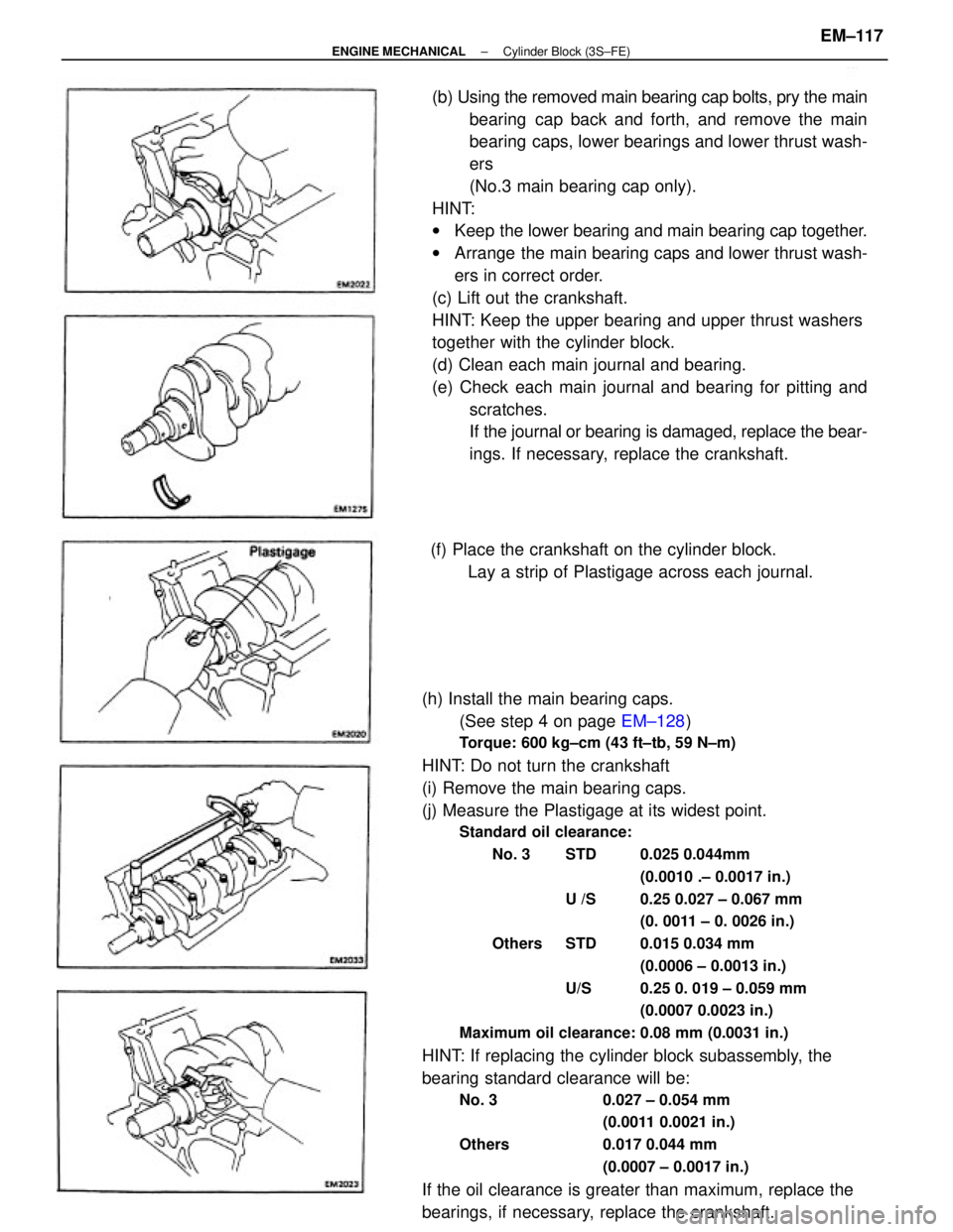
bearings, if necessary, replace the crankshaft.(b) Using the removed main bearing cap bolts, pry the main
bearing cap back and forth, and remove the main
bearing caps, lower bearings and lower thrust wash-
ers
(No.3 main bearing cap only).
HINT:
wKeep the lower bearing and main bearing cap together.
wArrange the main bearing caps and lower thrust wash-
ers in correct order.
(c) Lift out the crankshaft.
HINT: Keep the upper bearing and upper thrust washers
together with the cylinder block.
(d) Clean each main journal and bearing.
(e) Check each main journal and bearing for pitting and
scratches.
If the journal or bearing is damaged, replace the bear-
ings. If necessary, replace the crankshaft.
(f) Place the crankshaft on the cylinder block.
Lay a strip of Plastigage across each journal.
± ENGINE MECHANICALCylinder Block (3S±FE)EM±117
Page 1306 of 2389

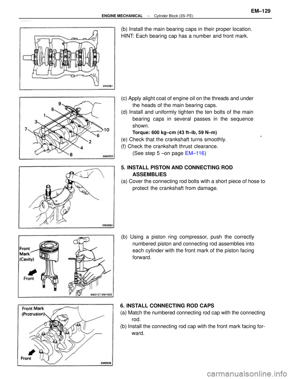
(c) Apply alight coat of engine oil on the threads and under
the heads of the main bearing caps.
(d) Install and uniformly tighten the ten bolts of the main
bearing caps in several passes in the sequence
shown.
Torque: 600 kg±cm (43 ft±ib, 59 N±m)
(e) Check that the crankshaft turns smoothly.
(f) Check the crankshaft thrust clearance.
(See step 5 ±on page EM±116)
6. INSTALL CONNECTING ROD CAPS
(a) Match the numbered connecting rod cap with the connecting
rod.
(b) Install the connecting rod cap with the front mark facing for-
ward. (b) Using a piston ring compressor, push the correctly
numbered piston and connecting rod assemblies into
each cylinder with the front mark of the piston facing
forward. 5. INSTALL PISTON AND CONNECTING ROD
ASSEMBLIES
(a) Cover the connecting rod bolts with a short piece of hose to
protect the crankshaft from damage. (b) Install the main bearing caps in their proper location.
HINT: Each bearing cap has a number and front mark.
± ENGINE MECHANICALCylinder Block (3S±FE)EM±129
Page 1307 of 2389
(c) Apply a light of engine oil on the threads and under the
nuts of the connecting rod cap.
(d) Install and alternately tighten the nuts of the connect-
ing rod cap in several passes.
Torque: 500 kg±cm (36 ft±Ib, 49 N±m)
(e) Check that the crankshaft turns smoothly.
M Check the connecting rod thrust clearance.
(See step 2 on page EM±114)
7. INSTALL REAR OIL SEAL RETAINER
Install a new gasket and the retainer with the six bolts.
Torque: 95 kg±cm (82 in.±Ib, 9.3 N±m)
± ENGINE MECHANICALCylinder Block (3S±FE)EM±130
Page 1308 of 2389
POST ASSEMBLY
1. INSTALL OIL PUMP AND OIL PAN
(See page LU±14)
2. INSTALL WATER PUMP (See page CO±7)
3. INSTALL CYLINDER HEAD (See page EM±67)
4. INSTALL PULLEYS AND TIMING BELT
(See page EM±29)
5. INSTALL ALTERNATOR (See page CH±14)
6. INSTALL DISTRIBUTOR (See page IG±16)
7. REMOVE ENGINE STAND
8. INSTALL REAR END PLATE
Torque: 95 kg±cm (82 ft±Ib, 9.3 N±m)
9. (M/T)
INSTALL FLYWHEEL
(a) Apply adhesive to two or three threads of the mount bolt
end.
Adhesive: Part No.08833±00070, THREE BOND 1324
or equivalent
10. (A/T)
INSTALL DRIVE PLATE
(See procedure step 9)
Torque: 850 kg±cm (61 ft±Ib, 83 N±m)
11. (M/T)
INSTALL CLUTCH DISC AND COVER (b) Install the flywheel on the crankshaft.
(c) Install and uniformly tighten the mount bolts in several
passes in the sequence shown.
Torque: 900 kg±cm (65 ft±Ib. 88 N±m)
± ENGINE MECHANICALCylinder Block (3S±FE)EM±131
Page 1309 of 2389

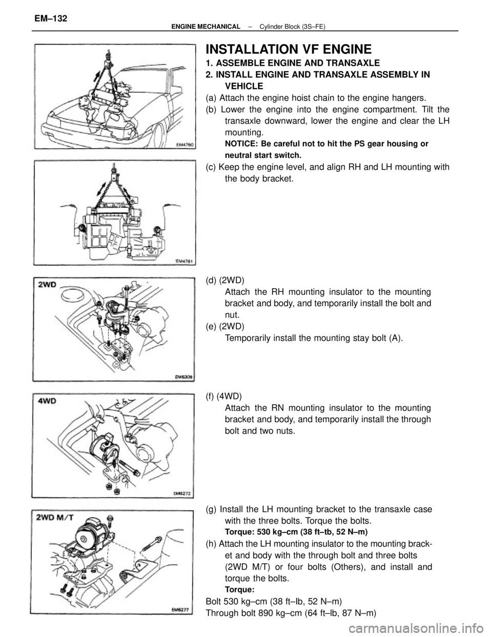
INSTALLATION VF ENGINE
1. ASSEMBLE ENGINE AND TRANSAXLE
2. INSTALL ENGINE AND TRANSAXLE ASSEMBLY IN
VEHICLE
(a) Attach the engine hoist chain to the engine hangers.
(b) Lower the engine into the engine compartment. Tilt the
transaxle downward, lower the engine and clear the LH
mounting.
NOTICE: Be careful not to hit the PS gear housing or
neutral start switch.
(c) Keep the engine level, and align RH and LH mounting with
the body bracket.
(g) Install the LH mounting bracket to the transaxle case
with the three bolts. Torque the bolts.
Torque: 530 kg±cm (38 ft±tb, 52 N±m)
(h) Attach the LH mounting insulator to the mounting brack-
et and body with the through bolt and three bolts
(2WD M/T) or four bolts (Others), and install and
torque the bolts.
Torque:
Bolt 530 kg±cm (38 ft±Ib, 52 N±m)
Through bolt 890 kg±cm (64 ft±lb, 87 N±m) (d) (2WD)
Attach the RH mounting insulator to the mounting
bracket and body, and temporarily install the bolt and
nut.
(e) (2WD)
Temporarily install the mounting stay bolt (A).
(f) (4WD)
Attach the RN mounting insulator to the mounting
bracket and body, and temporarily install the through
bolt and two nuts.
± ENGINE MECHANICALCylinder Block (3S±FE)EM±132
Page 1310 of 2389
(j) (4WD)
Torque the through bolt and two nuts of the RH
mounting insulator.
Torque:
Nut 530 kg±cm (38 ft±Ib, 62 N±m)
Through bolt 890 kg±cm (64 ft±lb, 87 N±m)
(k) Remove the engine hoist chain from the engine. (i) (2WD)
Torque the bolt and four nuts of the RH mounting in-
sulator. Do not torque the bolt (A) yet.
Torque:
Nut To bracket 530 kg±cm (38 ft±Ib, 52 N±m)
To body 900 kg±cm (65 ft±Ib, 88 N±m)
Bolt 650 kg±cm (47 ft±Ib, 64 N±m)
3. INSTALL ENGINE RH MOUNTING STAY
(2WD)
Install the mounting stay with the three botts. Torque the bolts.
Torque: 740 kg±cm (54 ft±lb, 73 N±m)
(4WD)
Install the mounting stay with the bolt and nut. Torque
the bolt and nut.
Torque: 740 kg±cm (54 ft±Ib, 73 N±m)
± ENGINE MECHANICALCylinder Block (3S±FE)EM±133
Page 1311 of 2389

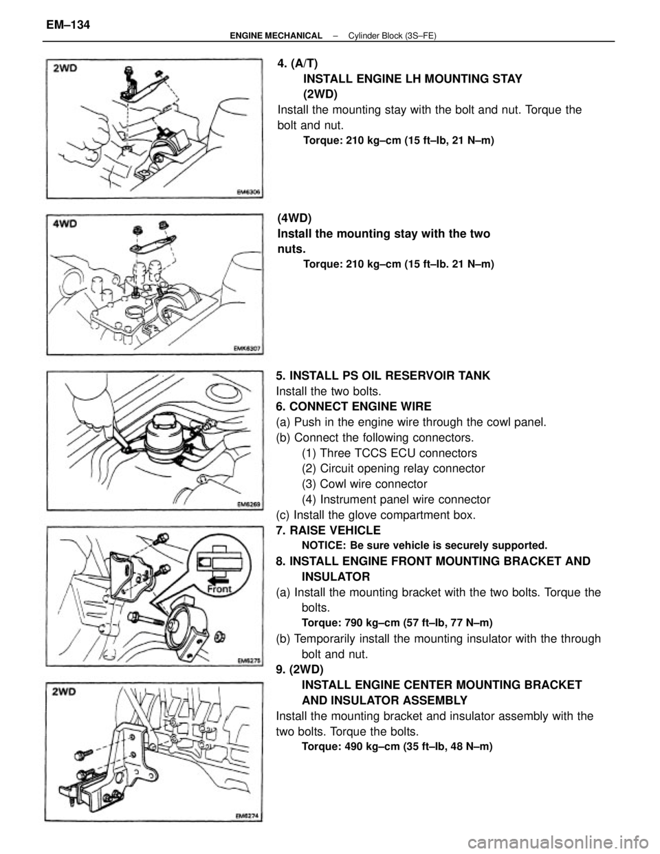
5. INSTALL PS OIL RESERVOIR TANK
Install the two bolts.
6. CONNECT ENGINE WIRE
(a) Push in the engine wire through the cowl panel.
(b) Connect the following connectors.
(1) Three TCCS ECU connectors
(2) Circuit opening relay connector
(3) Cowl wire connector
(4) Instrument panel wire connector
(c) Install the glove compartment box.
7. RAISE VEHICLE
NOTICE: Be sure vehicle is securely supported.
8. INSTALL ENGINE FRONT MOUNTING BRACKET AND
INSULATOR
(a) Install the mounting bracket with the two bolts. Torque the
bolts.
Torque: 790 kg±cm (57 ft±Ib, 77 N±m)
(b) Temporarily install the mounting insulator with the through
bolt and nut.
9. (2WD)
INSTALL ENGINE CENTER MOUNTING BRACKET
AND INSULATOR ASSEMBLY
Install the mounting bracket and insulator assembly with the
two bolts. Torque the bolts.
Torque: 490 kg±cm (35 ft±Ib, 48 N±m)
4. (A/T)
INSTALL ENGINE LH MOUNTING STAY
(2WD)
Install the mounting stay with the bolt and nut. Torque the
bolt and nut.
Torque: 210 kg±cm (15 ft±Ib, 21 N±m)
(4WD)
Install the mounting stay with the two
nuts.
Torque: 210 kg±cm (15 ft±Ib. 21 N±m)
± ENGINE MECHANICALCylinder Block (3S±FE)EM±134