Page 1220 of 2389
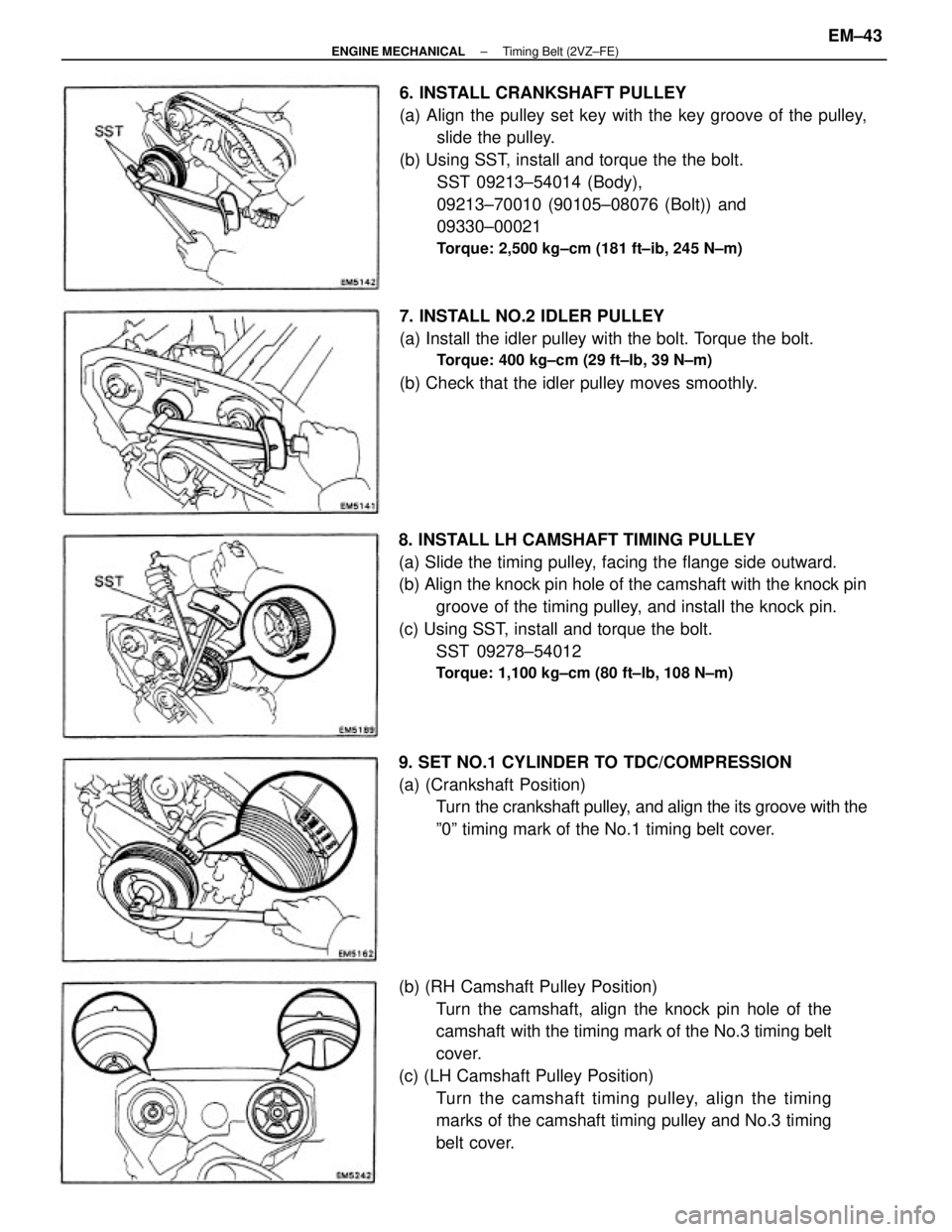
8. INSTALL LH CAMSHAFT TIMING PULLEY
(a) Slide the timing pulley, facing the flange side outward.
(b) Align the knock pin hole of the camshaft with the knock pin
groove of the timing pulley, and install the knock pin.
(c) Using SST, install and torque the bolt.
SST 09278±54012
Torque: 1,100 kg±cm (80 ft±lb, 108 N±m)
6. INSTALL CRANKSHAFT PULLEY
(a) Align the pulley set key with the key groove of the pulley,
slide the pulley.
(b) Using SST, install and torque the the bolt.
SST 09213±54014 (Body),
09213±70010 (90105±08076 (Bolt)) and
09330±00021
Torque: 2,500 kg±cm (181 ft±ib, 245 N±m)
(b) (RH Camshaft Pulley Position)
Turn the camshaft, align the knock pin hole of the
camshaft with the timing mark of the No.3 timing belt
cover.
(c) (LH Camshaft Pulley Position)
Turn the camshaft timing pulley, align the timing
marks of the camshaft timing pulley and No.3 timing
belt cover. 9. SET NO.1 CYLINDER TO TDC/COMPRESSION
(a) (Crankshaft Position)
Turn the crankshaft pulley, and align the its groove with the
º0º timing mark of the No.1 timing belt cover. 7. INSTALL NO.2 IDLER PULLEY
(a) Install the idler pulley with the bolt. Torque the bolt.
Torque: 400 kg±cm (29 ft±lb, 39 N±m)
(b) Check that the idler pulley moves smoothly.
± ENGINE MECHANICALTiming Belt (2VZ±FE)EM±43
Page 1222 of 2389
12. SET TIMING BELT TENSIONER
(a) Place a plate washer between the tensioner and a block.
(b) Using a press, slowly press in the push rod using 100
± 1,000 kg (220 ± 2,205 ib, 981 ± 9,807 N) of pressure.
(c) Align the holes of the push rod and housing, pass a
1.27 mm hexagon wrench (sized 1.27 mm) through the
holes to keep the setting position of the push rod.
(d) Release the press.
(e) Install the dust boot to the tensioner. (g) Using SST, install and torque the bolt.
SST09249±63010 and 09278±54012
Torque: 760 kg±cm (55 ft±lb, 75 N±m)
HINT: Use a torque wrench with a fulcrum length of 340
mm (13.39 in.). (f) Using SST, align the knock pin hole of the camshaft with
the knock pin groove of the pulley and install the
knock pin.
SST 09278±54012
13. INSTALL TIMING BELT TENSIONER
(a) Install the tensioner with the two bolts.
Torque: 270 kg±cm (20 ft±lb, 26 N±m)
± ENGINE MECHANICALTiming Belt (2VZ±FE)EM±45
Page 1223 of 2389
16. INSTALL NO.2 TIMING BELT COVER
(a) Install the gasket to the timing belt cover.
(b) Install the timing belt cover with the eight bolts.
HINT: Use the bolts indicated by A, B and C.
17. INSTALL SPARK PLUGS (See page IG±11 )
Torque: 180 k9±cm (13 ft±Ib, 18 N±m)
14. CHECK VALVE TIMING
(a) Turn the crankshaft pulley two revolutions from TDC
to TDC.
HINT: Always turn the crankshaft clockwise.
(b) Check that each pulley aligns with the timing marks as
shown in the figure.
If the marks do not align, remove the timing belt and
reinstall it.
15. INSTALL ENGINE RH MOUNTING BRACKET
Install the mounting bracket with the three bolt.
Torque: 410 kg±cm (30 ft±lb, 39 N±m)
(b) Remove the 1.27 mm hexagon wrench (sized 1.27
mm) from the tensioner.
± ENGINE MECHANICALTiming Belt (2VZ±FE)EM±46
Page 1224 of 2389
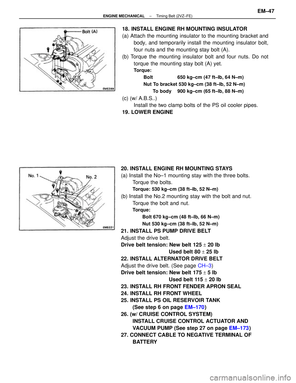
20. INSTALL ENGINE RH MOUNTING STAYS
(a) Install the No±1 mounting stay with the three bolts.
Torque the bolts.
Torque: 530 kg±cm (38 ft±Ib, 52 N±m)
(b) Install the No.2 mounting stay with the bolt and nut.
Torque the bolt and nut.
Torque:
Bolt 670 kg±cm (48 ft±Ib, 66 N±m)
Nut 530 kg±cm (38 ft±Ib, 52 N±m)
21. INSTALL PS PUMP DRIVE BELT
Adjust the drive belt.
Drive belt tension: New belt 125
+ 20 Ib
Used belt 80
+ 25 Ib
22. INSTALL ALTERNATOR DRIVE BELT
Adjust the drive belt. (See page CH±3)
Drive belt tension: New belt 175
+ 5 Ib
Used belt 115
+ 20 Ib
23. INSTALL RH FRONT FENDER APRON SEAL
24. INSTALL RH FRONT WHEEL
25. INSTALL PS OIL RESERVOIR TANK
(See step 6 on page EM±170)
26. (w/ CRUISE CONTROL SYSTEM)
INSTALL CRUISE CONTROL ACTUATOR AND
VACUUM PUMP (See step 27 on page EM±173)
27. CONNECT CABLE TO NEGATIVE TERMINAL OF
BATTERY 18. INSTALL ENGINE RH MOUNTING INSULATOR
(a) Attach the mounting insulator to the mounting bracket and
body, and temporarily install the mounting insulator bolt,
four nuts and the mounting stay bolt (A).
(b) Torque the mounting insulator bolt and four nuts. Do not
torque the mounting stay bolt (A) yet.
Torque:
Bolt 650 kg±cm (47 ft±Ib, 64 N±m)
Nut To bracket 530 kg±cm (38 ft±lb, 52 N±m)
To body 900 kg±cm (65 ft±lb, 88 N±m)
(c) (w/ A.B.S..)
Install the two clamp bolts of the PS oil cooler pipes.
19. LOWER ENGINE
± ENGINE MECHANICALTiming Belt (2VZ±FE)EM±47
Page 1241 of 2389
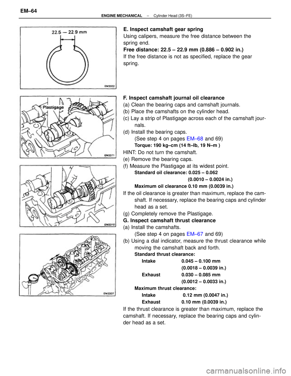
F. Inspect camshaft journal oil clearance
(a) Clean the bearing caps and camshaft journals.
(b) Place the camshafts on the cylinder head.
(c) Lay a strip of Plastigage across each of the camshaft jour-
nals.
(d) Install the bearing caps.
(See step 4 on pages EM±68 and 69)
Torque: 190 kg±cm (14 ft±Ib, 19 N±m )
HINT: Do not turn the camshaft.
(e) Remove the bearing caps.
(f) Measure the Plastigage at its widest point.
Standard oil clearance: 0.025 ± 0.062
(0.0010 ± 0.0024 in.)
Maximum oil clearance 0.10 mm (0.0039 in.)
If the oil clearance is greater than maximum, replace the cam-
shaft. If necessary, replace the bearing caps and cylinder
head as a set.
(g) Completely remove the Plastigage.
G. Inspect camshaft thrust clearance
(a) Install the camshafts.
(See step 4 on pages EM±67 and 69)
(b) Using a dial indicator, measure the thrust clearance while
moving the camshaft back and forth.
Standard thrust clearance:
Intake 0.045 ± 0.100 mm
(0.0018 ± 0.0039 in.)
Exhaust 0.030 ± 0.085 mm
(0.0012 ± 0.0033 in.)
Maximum thrust clearance:
Intake 0.12 mm (0.0047 in.)
Exhaust 0.10 mm (0.0039 in.)
If the thrust clearance is greater than maximum, replace the
camshaft. If necessary, replace the bearing caps and cylin-
der head as a set.E. Inspect camshaft gear spring
Using calipers, measure the free distance between the
spring end.
Free distance: 22.5 ± 22.9 mm (0.886 ± 0.902 in.)
If the free distance is not as specified, replace the gear
spring.
± ENGINE MECHANICALCylinder Head (3S±FE)EM±64
Page 1244 of 2389
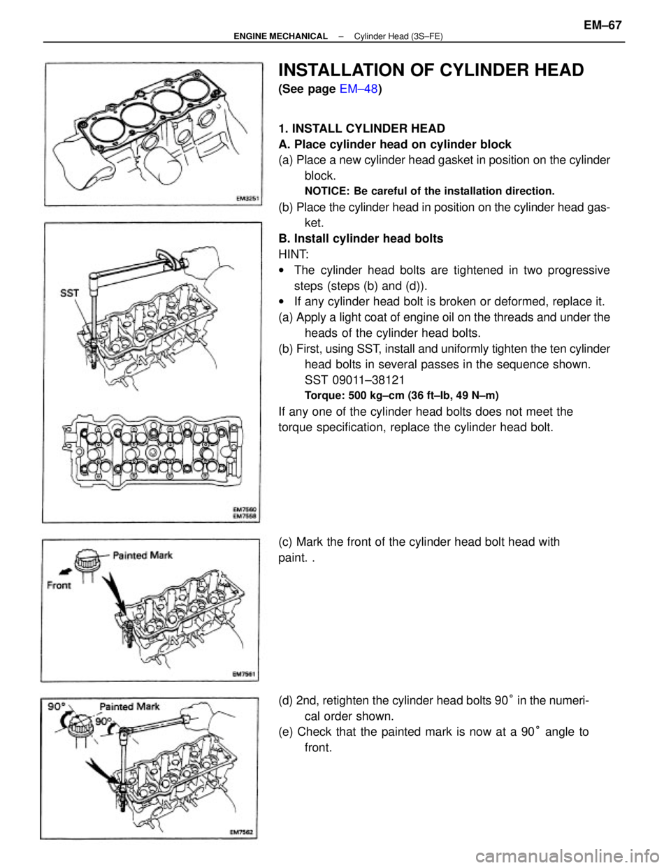
1. INSTALL CYLINDER HEAD
A. Place cylinder head on cylinder block
(a) Place a new cylinder head gasket in position on the cylinder
block.
NOTICE: Be careful of the installation direction.
(b) Place the cylinder head in position on the cylinder head gas-
ket.
B. Install cylinder head bolts
HINT:
wThe cylinder head bolts are tightened in two progressive
steps (steps (b) and (d)).
wIf any cylinder head bolt is broken or deformed, replace it.
(a) Apply a light coat of engine oil on the threads and under the
heads of the cylinder head bolts.
(b) First, using SST, install and uniformly tighten the ten cylinder
head bolts in several passes in the sequence shown.
SST 09011±38121
Torque: 500 kg±cm (36 ft±Ib, 49 N±m)
If any one of the cylinder head bolts does not meet the
torque specification, replace the cylinder head bolt.
(d) 2nd, retighten the cylinder head bolts 90° in the numeri-
cal order shown.
(e) Check that the painted mark is now at a 90° angle to
front.
INSTALLATION OF CYLINDER HEAD
(See page EM±48)
(c) Mark the front of the cylinder head bolt head with
paint. .
± ENGINE MECHANICALCylinder Head (3S±FE)EM±67
Page 1245 of 2389
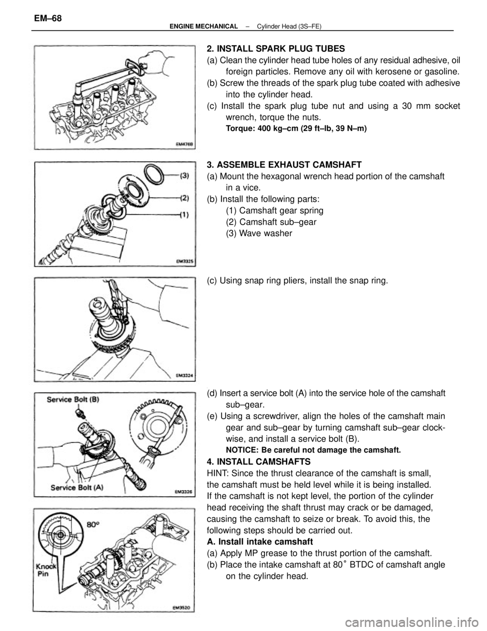
.
(d) Insert a service bolt (A) into the service hole of the camshaft
sub±gear.
(e) Using a screwdriver, align the holes of the camshaft main
gear and sub±gear by turning camshaft sub±gear clock-
wise, and install a service bolt (B).
NOTICE: Be careful not damage the camshaft.
4. INSTALL CAMSHAFTS
HINT: Since the thrust clearance of the camshaft is small,
the camshaft must be held level while it is being installed.
If the camshaft is not kept level, the portion of the cylinder
head receiving the shaft thrust may crack or be damaged,
causing the camshaft to seize or break. To avoid this, the
following steps should be carried out.
A. Install intake camshaft
(a) Apply MP grease to the thrust portion of the camshaft.
(b) Place the intake camshaft at 80° BTDC of camshaft angle
on the cylinder head. 2. INSTALL SPARK PLUG TUBES
(a) Clean the cylinder head tube holes of any residual adhesive, oil
foreign particles. Remove any oil with kerosene or gasoline.
(b) Screw the threads of the spark plug tube coated with adhesive
into the cylinder head.
(c) Install the spark plug tube nut and using a 30 mm socket
wrench, torque the nuts.
Torque: 400 kg±cm (29 ft±lb, 39 N±m)
3. ASSEMBLE EXHAUST CAMSHAFT
(a) Mount the hexagonal wrench head portion of the camshaft
in a vice.
(b) Install the following parts:
(1) Camshaft gear spring
(2) Camshaft sub±gear
(3) Wave washer
(c) Using snap ring pliers, install the snap ring.
± ENGINE MECHANICALCylinder Head (3S±FE)EM±68
Page 1246 of 2389
(e) Apply alight coat of engine oil on the threads and under
the heads of the bearing cap bolts.
(f) Install and uniformly tighten the ten bearing cap bolts in
several passes in the sequence shown.
Torque: 190 kg±cm (14 ft±Ib, 19 N±m)
(c) Apply seal packing to the front bearing cap as shown.
Seal packing: Part No. 08826±00080 or equivalent
(h) Using SST, tap in the oil seal.
SST 09223±46011 (d) Install the bearing caps in their proper locations.
(g) Apply MP grease to a new oil seal lip.
± ENGINE MECHANICALCylinder Head (3S±FE)EM±69