Page 956 of 2389
3. INSTALL DECELERATION SENSOR
(a) Install the deceleration sensor to the bracket with the
two screws.
Torque: 32.5 kg±cm (28 in.±Ib, 3.2 N±m)
(b) Install the connector to the clamp on the bracket.
(c) Check that the deceleration sensor is installed prop-
erly.
4. INSTALL A.B.S. COMPUTER
(a) Connect the three connectors and insert the wire har-
ness to the clamp.
(b) Set the computer in place, and install it with the five
screws.
Torque: 32.5 kg±cm (28 in.±Ib, 3.2 N±m)
(c) Install the computer cover.
± BRAKE SYSTEMAnti±lock Brake System (A.B.S.)BR±105
Page 976 of 2389

CHECK AND ADJUSTMENT OF
CLUTCH PEDAL
1. CHECK THAT PEDAL HEIGHT IS CORRECT
Pedal height from asphalt shaft 181 ± 191 mm
(7:13 ± 7.52 in.)
2. IF NECESSARY, ADJUST PEDAL HEIGHT
(a) Remove the instrument lower finish panel and discon-
nect the air duct.
(b) Loosen the lock nut and turn the stopper bolt (w/o
Cruise control system) or clutch switch (w/ Cruise
control system) until the height is correct. Tighten the
lock nut.
HINT: Before rotating the clutch switch for pedal height
adjustment, disconnect the clutch switch connector.
3. CHECK THAT PEDAL FREEPLAY AND PUSH ROD
PLAY ARE CORRECT
(Pedal Freeplay)
Push in the pedal until the beginning of clutch resistance
is felt.
Pedal freeplay: 5 ± 15 mm (0.20 ± 0.59 in.)
Push rod play at pedal top: 1.0 ± 5.0 mm
(0.039 ± 0.197 in.)
4. IF NECESSARY, ADJUST PEDAL FREEPLAY AND
PUSH ROD PLAY
(a) Loosen the lock nut and turn the push rod until the free-
play and push rod play are correct.
(b) Tighten the lock nut.
(e) After adjusting the pedal freeplay, check the pedal
height.
(d) Connect the air duct and install the lower finish panel.
5. INSPECT CLUTCH RELEASE POINT
(a) Pull the parking brake lever and install wheel stopper.
(b) Start the engine and idle the engine.
(e) Without depressing the clutch pedal, slowly shift the
shift lever into reverse position until the gears contact.
(d) Gradually depress the clutch pedal and measure the
stroke distance from the point the gear noise stops
(release point) up to the full stroke end position.
Standard distance: 25 mm (0.98 in.) or more
(From pedal stroke end position to release point)
If the distance is not as specified, perform the following
operation.
wInspect pedal height.
wInspect push rod play and pedal free play.
wBleed the clutch line.
wInspect the clutch cover and disc.
± CLUTCHCheck and Adjustment of Clutch PedalCL±3
Page 977 of 2389

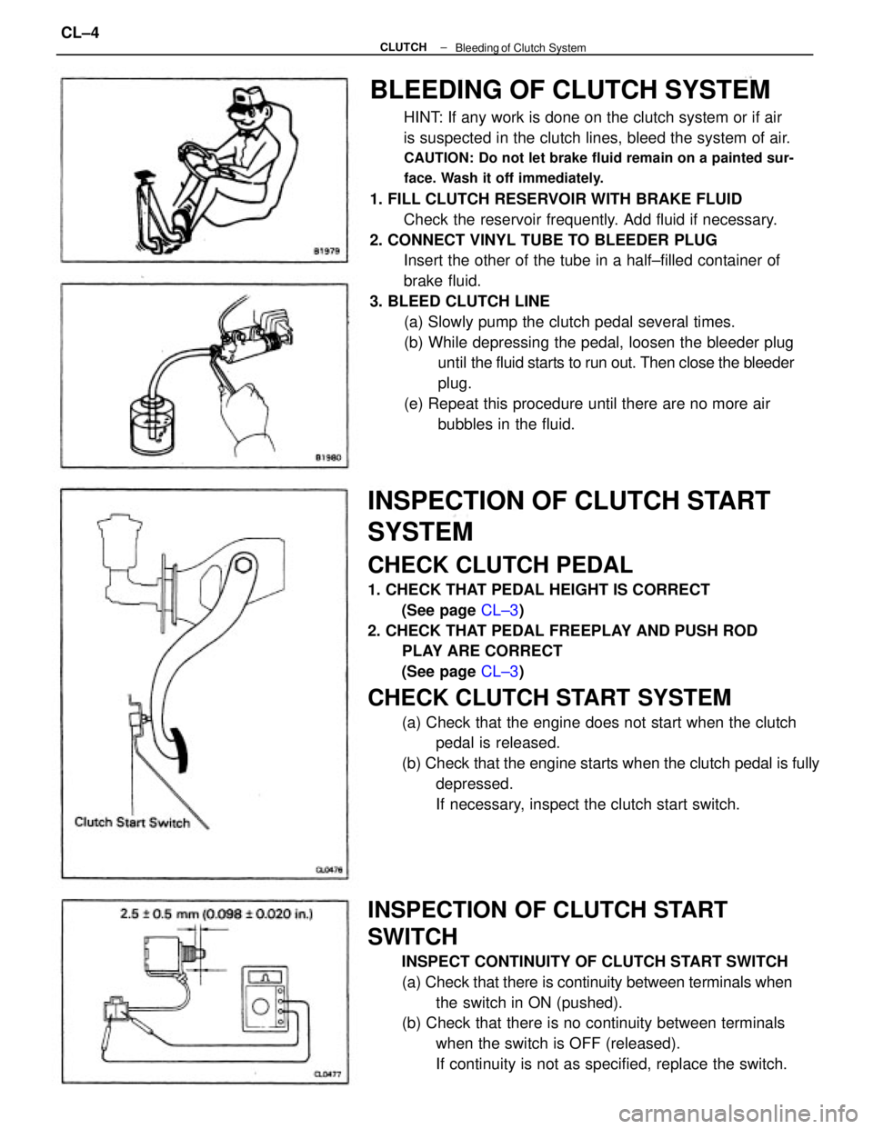
BLEEDING OF CLUTCH SYSTEM
HINT: If any work is done on the clutch system or if air
is suspected in the clutch lines, bleed the system of air.
CAUTION: Do not let brake fluid remain on a painted sur-
face. Wash it off immediately.
1. FILL CLUTCH RESERVOIR WITH BRAKE FLUID
Check the reservoir frequently. Add fluid if necessary.
2. CONNECT VINYL TUBE TO BLEEDER PLUG
Insert the other of the tube in a half±filled container of
brake fluid.
3. BLEED CLUTCH LINE
(a) Slowly pump the clutch pedal several times.
(b) While depressing the pedal, loosen the bleeder plug
until the fluid starts to run out. Then close the bleeder
plug.
(e) Repeat this procedure until there are no more air
bubbles in the fluid.
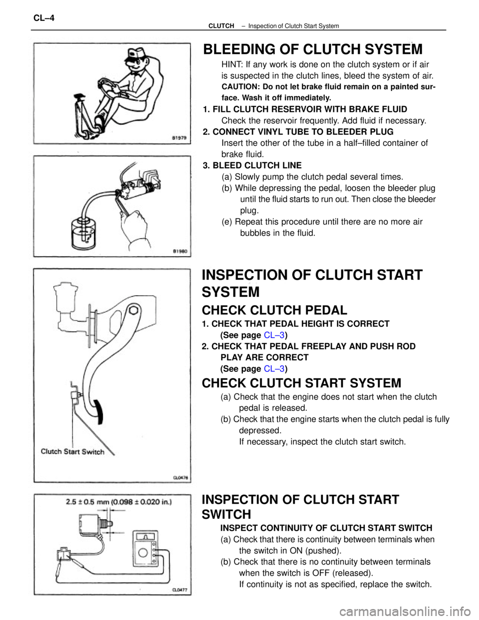
INSPECTION OF CLUTCH START
SYSTEM
CHECK CLUTCH PEDAL
1. CHECK THAT PEDAL HEIGHT IS CORRECT
(See page CL±3)
2. CHECK THAT PEDAL FREEPLAY AND PUSH ROD
PLAY ARE CORRECT
(See page CL±3)
CHECK CLUTCH START SYSTEM
(a) Check that the engine does not start when the clutch
pedal is released.
(b) Check that the engine starts when the clutch pedal is fully
depressed.
If necessary, inspect the clutch start switch.
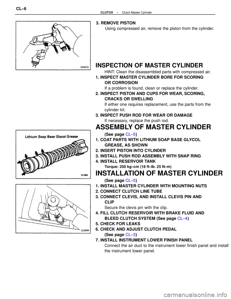
INSPECTION OF CLUTCH START
SWITCH
INSPECT CONTINUITY OF CLUTCH START SWITCH
(a) Check that there is continuity between terminals when
the switch in ON (pushed).
(b) Check that there is no continuity between terminals
when the switch is OFF (released).
If continuity is not as specified, replace the switch.
± CLUTCH
Bleeding of Clutch SystemCL±4
Page 978 of 2389

BLEEDING OF CLUTCH SYSTEM
HINT: If any work is done on the clutch system or if air
is suspected in the clutch lines, bleed the system of air.
CAUTION: Do not let brake fluid remain on a painted sur-
face. Wash it off immediately.
1. FILL CLUTCH RESERVOIR WITH BRAKE FLUID
Check the reservoir frequently. Add fluid if necessary.
2. CONNECT VINYL TUBE TO BLEEDER PLUG
Insert the other of the tube in a half±filled container of
brake fluid.
3. BLEED CLUTCH LINE
(a) Slowly pump the clutch pedal several times.
(b) While depressing the pedal, loosen the bleeder plug
until the fluid starts to run out. Then close the bleeder
plug.
(e) Repeat this procedure until there are no more air
bubbles in the fluid.
INSPECTION OF CLUTCH START
SYSTEM
CHECK CLUTCH PEDAL
1. CHECK THAT PEDAL HEIGHT IS CORRECT
(See page CL±3)
2. CHECK THAT PEDAL FREEPLAY AND PUSH ROD
PLAY ARE CORRECT
(See page CL±3)
CHECK CLUTCH START SYSTEM
(a) Check that the engine does not start when the clutch
pedal is released.
(b) Check that the engine starts when the clutch pedal is fully
depressed.
If necessary, inspect the clutch start switch.
INSPECTION OF CLUTCH START
SWITCH
INSPECT CONTINUITY OF CLUTCH START SWITCH
(a) Check that there is continuity between terminals when
the switch in ON (pushed).
(b) Check that there is no continuity between terminals
when the switch is OFF (released).
If continuity is not as specified, replace the switch.
± CLUTCHInspection of Clutch Start SystemCL±4
Page 980 of 2389

INSPECTION OF MASTER CYLINDER
HINT: Clean the disassembled parts with compressed air.
1. INSPECT MASTER CYLINDER BORE FOR SCORING
OR CORROSION
If a problem is found, clean or replace the cylinder.
2. INSPECT PISTON AND CUPS FOR WEAR, SCORING,
CRACKS OR SWELLING
If either one requires replacement, use the parts from the
cylinder kit.
3. INSPECT PUSH ROD FOR WEAR OR DAMAGE
If necessary, replace the push rod.
ASSEMBLY OF MASTER CYLINDER
(See page CL±5)
1. COAT PARTS WITH LITHIUM SOAP BASE GLYCOL
GREASE, AS SHOWN
2. INSERT PISTON INTO CYLINDER
3. INSTALL PUSH ROD ASSEMBLY WITH SNAP RING
4. INSTALL RESERVOIR TANK
Torque: 250 kg±cm (18 ft±Ib. 25 N±m)
INSTALLATION OF MASTER CYLINDER
(See page CL±5)
1. INSTALL MASTER CYLINDER WITH MOUNTING NUTS
2. CONNECT CLUTCH LINE TUBE
3. CONNECT CLEVIS, AND INSTALL CLEVIS PIN AND
CLIP
Secure the clevis pin with the clip.
4. FILL CLUTCH RESERVOIR WITH BRAKE FLUID AND
BLEED CLUTCH SYSTEM (See page CL±4)
5. CHECK FOR LEAKS
6. CHECK AND ADJUST CLUTCH PEDAL
(See page CL±3)
7. INSTALL INSTRUMENT LOWER FINISH PANEL
Connect the air duct to the instrument lower finish panel and install
the instrument lower panel. 3. REMOVE PISTON
Using compressed air, remove the piston from the cylinder.
± CLUTCHClutch Master CylinderCL±6
Page 981 of 2389
REMOVAL OF RELEASE CYLINDER
1. DISCONNECT CLUTCH LINE TUBE
Using SST, disconnect the tube. Use a container to catch
the brake fluid.
SST 09751±36011
2. REMOVE TWO BOLTS AND PULL OUT RELEASE
CYLINDER
3. REMOVE PISTON WITH SPRING
(a) Remove the boot and push rod from the cylinder.
(b) Using compressed air, remove the piston with spring
from the cylinder.
CLUTCH RELEASE CYLINDER
COMPONENTS
± CLUTCHClutch Release CylinderCL±7
Page 982 of 2389
INSPECTION OF RELEASE CYLINDER
HINT: Clean the disassembled part with compressed air.
1. INSPECT RELEASE CYLINDER BORE FOR SCORING
OR CORROSION
If a problem is found, clean or replace the cylinder.
2. INSPECT PISTON AND CUPS FOR WEAR, SCORING.
CRACKS OR SWELLING
If either one requires replacement, use the parts from the
cylinder kit.
3. INSPECT PUSH ROD FOR WEAR OR DAMAGE
If necessary, replace the push rod.
INSTALLATION OF RELEASE CYLINDER
(see page CL±7)
1. INSTALL RELEASE CYLINDER WITH TWO BOLTS
2. CONNECT CLUTCH LINE TUBE
Using SST, connect the tube.
SST. 09751±36011
Torque: 155 kg±cm (11 ft±Ib, 15 N±m)
3. FILL CLUTCH RESERVOIR WITH BRAKE FLUID AND
BLEED CLUTCH SYSTEM
(See page CL±4)
4. CHECK FOR LEAKS
ASSEMBLY OF RELEASE CYLINDER
(see page CL±7)
1. COAT PISTON WITH LITHIUM SOAP BASE GLYCOL
GREASE, AS SHOWN
2. INSERT PISTON WITH SPRING
3. INSTALL BOOT AND INSERT PUSH ROD
± CLUTCHClutch Release CylinderCL±8
Page 1022 of 2389

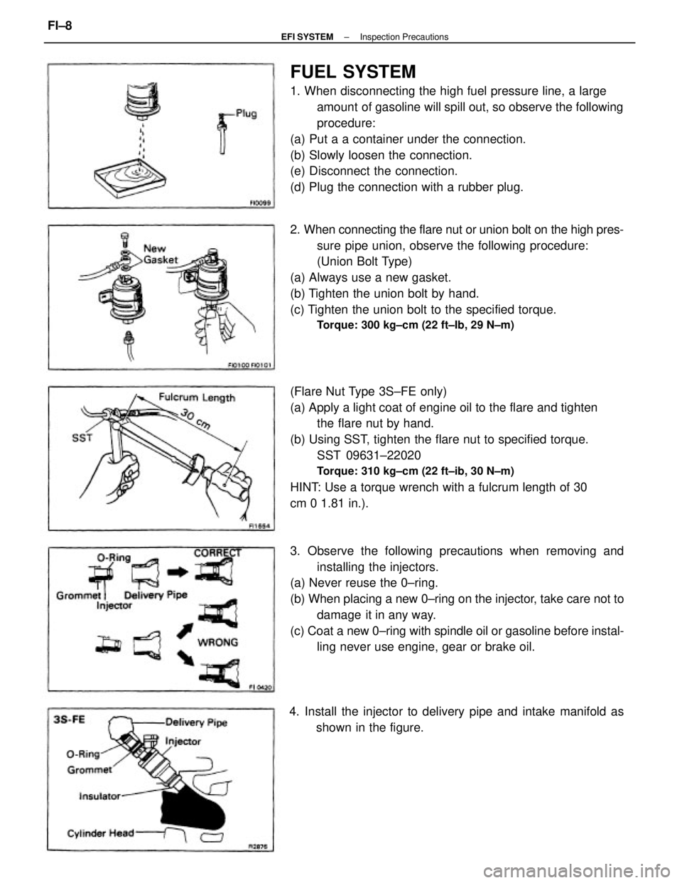
FUEL SYSTEM
1. When disconnecting the high fuel pressure line, a large
amount of gasoline will spill out, so observe the following
procedure:
(a) Put a a container under the connection.
(b) Slowly loosen the connection.
(e) Disconnect the connection.
(d) Plug the connection with a rubber plug.
(Flare Nut Type 3S±FE only)
(a) Apply a light coat of engine oil to the flare and tighten
the flare nut by hand.
(b) Using SST, tighten the flare nut to specified torque.
SST 09631±22020
Torque: 310 kg±cm (22 ft±ib, 30 N±m)
HINT: Use a torque wrench with a fulcrum length of 30
cm 0 1.81 in.). 2. When connecting the flare nut or union bolt on the high pres-
sure pipe union, observe the following procedure:
(Union Bolt Type)
(a) Always use a new gasket.
(b) Tighten the union bolt by hand.
(c) Tighten the union bolt to the specified torque.
Torque: 300 kg±cm (22 ft±Ib, 29 N±m)
3. Observe the following precautions when removing and
installing the injectors.
(a) Never reuse the 0±ring.
(b) When placing a new 0±ring on the injector, take care not to
damage it in any way.
(c) Coat a new 0±ring with spindle oil or gasoline before instal-
ling never use engine, gear or brake oil.
4. Install the injector to delivery pipe and intake manifold as
shown in the figure.
± EFI SYSTEMInspection PrecautionsFI±8