Page 1185 of 2389
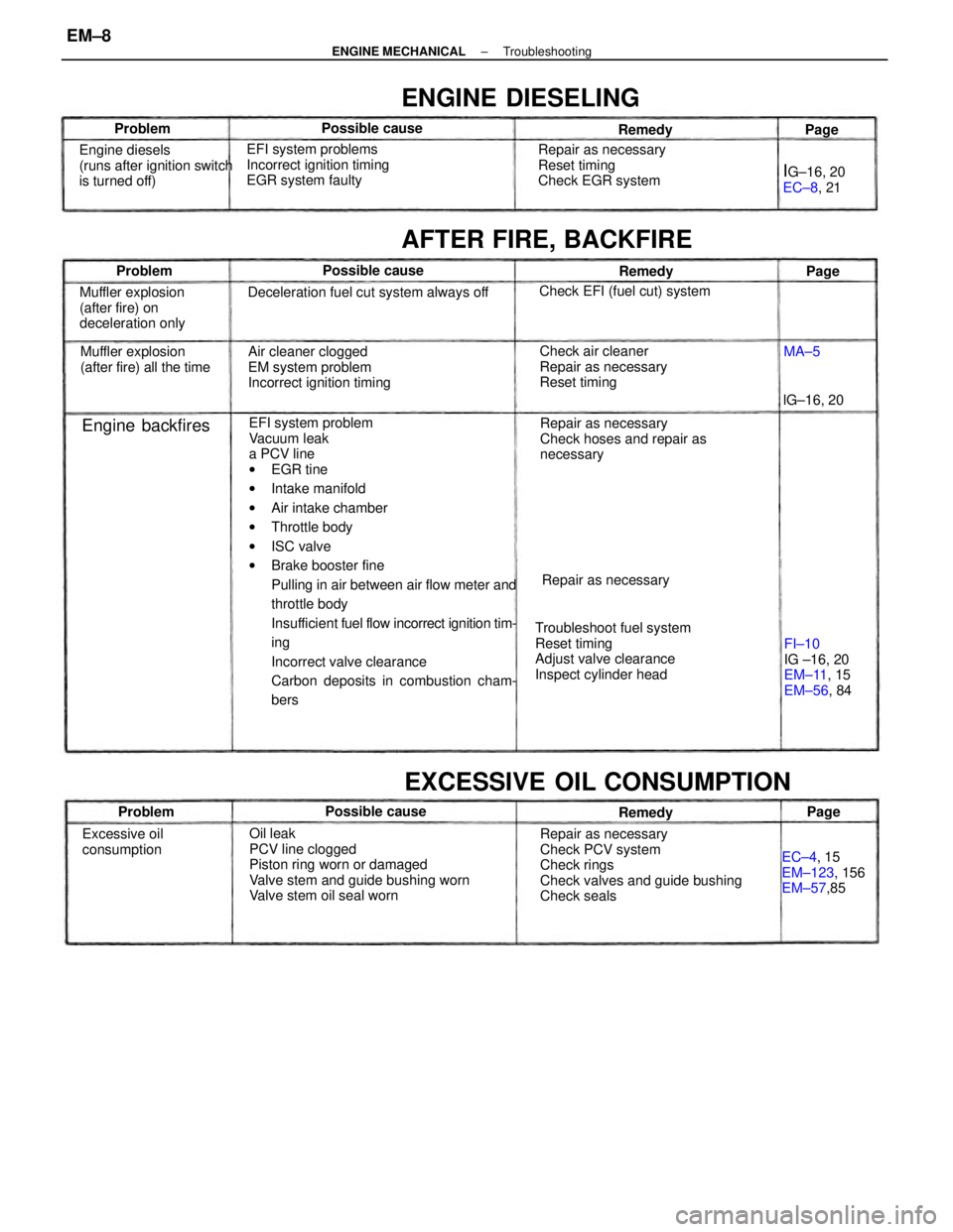
EFI system problem
Vacuum leak
a PCV line
wEGR tine
wIntake manifold
wAir intake chamber
wThrottle body
wISC valve
wBrake booster fine
Pulling in air between air flow meter and
throttle body
Insufficient fuel flow incorrect ignition tim-
ing
Incorrect valve clearance
Carbon deposits in combustion cham-
bers
Oil leak
PCV line clogged
Piston ring worn or damaged
Valve stem and guide bushing worn
Valve stem oil seal wornRepair as necessary
Check PCV system
Check rings
Check valves and guide bushing
Check seals Troubleshoot fuel system
Reset timing
Adjust valve clearance
Inspect cylinder headRepair as necessary
Check hoses and repair as
necessary Air cleaner clogged
EM system problem
Incorrect ignition timing EFI system problems
Incorrect ignition timing
EGR system faulty
Deceleration fuel cut system always off
Check air cleaner
Repair as necessary
Reset timing Repair as necessary
Reset timing
Check EGR system
EXCESSIVE OIL CONSUMPTION
Engine diesels
(runs after ignition switch
is turned off)
Muffler explosion
(after fire) on
deceleration only
FI±10
IG ±16, 20
EM±11, 15
EM±56, 84 Muffler explosion
(after fire) all the time
AFTER FIRE, BACKFIRE
EC±4, 15
EM±123, 156
EM±57,85
ENGINE DIESELING
Check EFI (fuel cut) system
Excessive oil
consumptionRepair as necessary
IG±16, 20
EC±8, 21
Engine backfires
Possible cause Possible cause
Possible causelG±16, 20 Problem
Problem
RemedyRemedy
ProblemRemedy
Page Page
MA±5Page
± ENGINE MECHANICALTroubleshootingEM±8
Page 1186 of 2389
Fuel leak
Air cleaner clogged
Incorrect ignition timing
EFI system problems
wInjector faulty
wDeceleration fuel cut system faulty
Idle speed too high
Spark plug faulty
EGR system always on
Low compression
Tires improperly inflated
Clutch slips
Brakes drag
Incorrect idle speed
Incorrect ignition timing
Vacuum leaks
wPCV line
wEGR line
wIntake manifold
wAir intake chamber
wThrottle body
wISC valve
wBrake booster line
EFI system problemsCheck ISC system
Inspect plugs
Check EGR system
Check compression
Inflate tires to proper pressure
Troubleshoot clutch
Troubleshoot brakesRepair as necessary
Check air cleaner
Reset timing
Repair as necessary
EXCESSIVE FUEL CONSUMPTION
Check ISC system
Reset timing
Repair as necessaryFI±116,118
IG±6, 10
EC±8, 21
EM±22
UNPLEASANT ODOR
Poor gasoline
mileage
FI±116, 118
IG±16, 20
Repair as necessaryMA±5
IG±16, 20
Unpleasant odorPossible cause Possible cause
Problem
ProblemRemedy
RemedyPage Page
± ENGINE MECHANICALTroubleshootingEM±9
Page 1198 of 2389
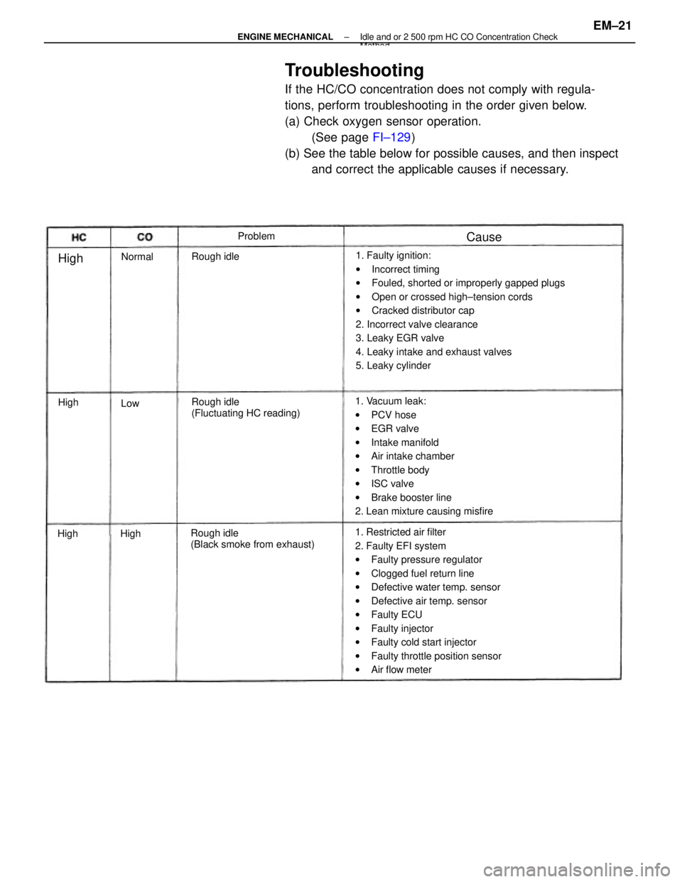
Troubleshooting
If the HC/CO concentration does not comply with regula-
tions, perform troubleshooting in the order given below.
(a) Check oxygen sensor operation.
(See page FI±129)
(b) See the table below for possible causes, and then inspect
and correct the applicable causes if necessary.
1. Faulty ignition:
wIncorrect timing
wFouled, shorted or improperly gapped plugs
wOpen or crossed high±tension cords
wCracked distributor cap
2. Incorrect valve clearance
3. Leaky EGR valve
4. Leaky intake and exhaust valves
5. Leaky cylinder
1. Restricted air filter
2. Faulty EFI system
wFaulty pressure regulator
wClogged fuel return line
wDefective water temp. sensor
wDefective air temp. sensor
wFaulty ECU
wFaulty injector
wFaulty cold start injector
wFaulty throttle position sensor
wAir flow meter 1. Vacuum leak:
wPCV hose
wEGR valve
wIntake manifold
wAir intake chamber
wThrottle body
wISC valve
wBrake booster line
2. Lean mixture causing misfire
Rough idle
(Black smoke from exhaust)Rough idle
(Fluctuating HC reading) Rough idleProblem
Normal
Cause
High
High
HighHigh
Low
± ENGINE MECHANICALIdle and or 2 500 rpm HC CO Concentration CheckMethod
EM±21
Page 1286 of 2389
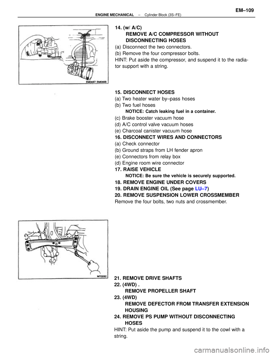
15. DISCONNECT HOSES
(a) Two heater water by±pass hoses
(b) Two fuel hoses
NOTICE: Catch leaking fuel in a container.
(c) Brake booster vacuum hose
(d) A/C control valve vacuum hoses
(e) Charcoal canister vacuum hose
16. DISCONNECT WIRES AND CONNECTORS
(a) Check connector
(b) Ground straps from LH fender apron
(e) Connectors from relay box
(d) Engine room wire connector
17. RAISE VEHICLE
NOTICE: Be sure the vehicle is securely supported.
18. REMOVE ENGINE UNDER COVERS
19. DRAIN ENGINE OIL (See page LU±7)
20. REMOVE SUSPENSION LOWER CROSSMEMBER
Remove the four bolts, two nuts and crossmember.
21. REMOVE DRIVE SHAFTS
22. (4WD) .
REMOVE PROPELLER SHAFT
23. (4WD)
REMOVE DEFECTOR FROM TRANSFER EXTENSION
HOUSING
24. REMOVE PS PUMP WITHOUT DISCONNECTING
HOSES
HINT: Put aside the pump and suspend it to the cowl with a
string.14. (w/ A/C)
REMOVE A/C COMPRESSOR WITHOUT
DISCONNECTING HOSES
(a) Disconnect the two connectors.
(b) Remove the four compressor bolts.
HINT: Put aside the compressor, and suspend it to the radia-
tor support with a string.
± ENGINE MECHANICALCylinder Block (3S±FE)EM±109
Page 1313 of 2389
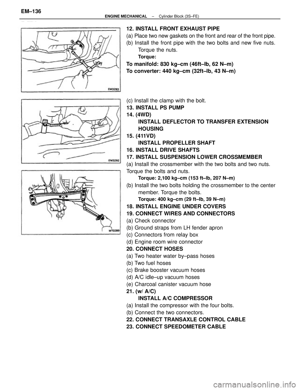
(c) Install the clamp with the bolt.
13. INSTALL PS PUMP
14. (4WD)
INSTALL DEFLECTOR TO TRANSFER EXTENSION
HOUSING
15. (411VD)
INSTALL PROPELLER SHAFT
16. INSTALL DRIVE SHAFTS
17. INSTALL SUSPENSION LOWER CROSSMEMBER
(a) Install the crossmember with the two bolts and two nuts.
Torque the bolts and nuts.
Torque: 2,100 kg±cm (153 ft±lb, 207 N±m)
(b) Install the two bolts holding the crossmember to the center
member. Torque the bolts.
Torque: 400 kg±cm (29 ft±Ib, 39 N±m)
18. INSTALL ENGINE UNDER COVERS
19. CONNECT WIRES AND CONNECTORS
(a) Check connector
(b) Ground straps from LH fender apron
(c) Connectors from relay box
(d) Engine room wire connector
20. CONNECT HOSES
(a) Two heater water by±pass hoses
(b) Two fuel hoses
(c) Brake booster vacuum hoses
(d) A/C idle±up vacuum hoses
(e) Charcoal canister vacuum hose
21. (w/ A/C)
INSTALL A/C COMPRESSOR
(a) Install the compressor with the four bolts.
(b) Connect the two connectors.
22. CONNECT TRANSAXLE CONTROL CABLE
23. CONNECT SPEEDOMETER CABLE 12. INSTALL FRONT EXHAUST PIPE
(a) Place two new gaskets on the front and rear of the front pipe.
(b) Install the front pipe with the two bolts and new five nuts.
Torque the nuts.
Torque:
To manifold: 830 kg±cm (46ft±Ib, 62 N±m)
To converter: 440 kg±cm (32ft±lb, 43 N±m)
± ENGINE MECHANICALCylinder Block (3S±FE)EM±136
Page 1318 of 2389
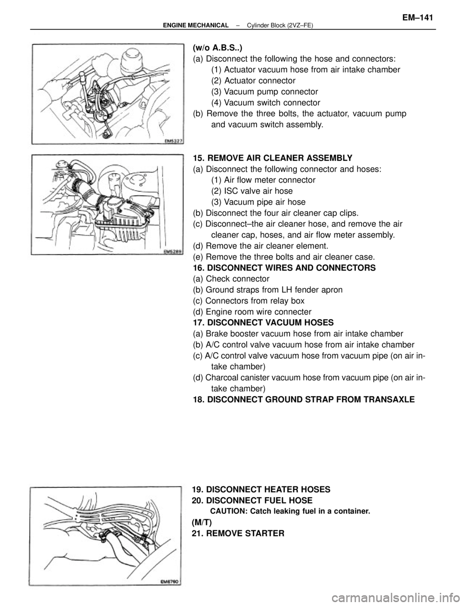
15. REMOVE AIR CLEANER ASSEMBLY
(a) Disconnect the following connector and hoses:
(1) Air flow meter connector
(2) ISC valve air hose
(3) Vacuum pipe air hose
(b) Disconnect the four air cleaner cap clips.
(c) Disconnect±the air cleaner hose, and remove the air
cleaner cap, hoses, and air flow meter assembly.
(d) Remove the air cleaner element.
(e) Remove the three bolts and air cleaner case.
16. DISCONNECT WIRES AND CONNECTORS
(a) Check connector
(b) Ground straps from LH fender apron
(c) Connectors from relay box
(d) Engine room wire connecter
17. DISCONNECT VACUUM HOSES
(a) Brake booster vacuum hose from air intake chamber
(b) A/C control valve vacuum hose from air intake chamber
(c) A/C control valve vacuum hose from vacuum pipe (on air in-
take chamber)
(d) Charcoal canister vacuum hose from vacuum pipe (on air in-
take chamber)
18. DISCONNECT GROUND STRAP FROM TRANSAXLE (w/o A.B.S..)
(a) Disconnect the following the hose and connectors:
(1) Actuator vacuum hose from air intake chamber
(2) Actuator connector
(3) Vacuum pump connector
(4) Vacuum switch connector
(b) Remove the three bolts, the actuator, vacuum pump
and vacuum switch assembly.
19. DISCONNECT HEATER HOSES
20. DISCONNECT FUEL HOSE
CAUTION: Catch leaking fuel in a container.
(M/T)
21. REMOVE STARTER
± ENGINE MECHANICALCylinder Block (2VZ±FE)EM±141
Page 1350 of 2389
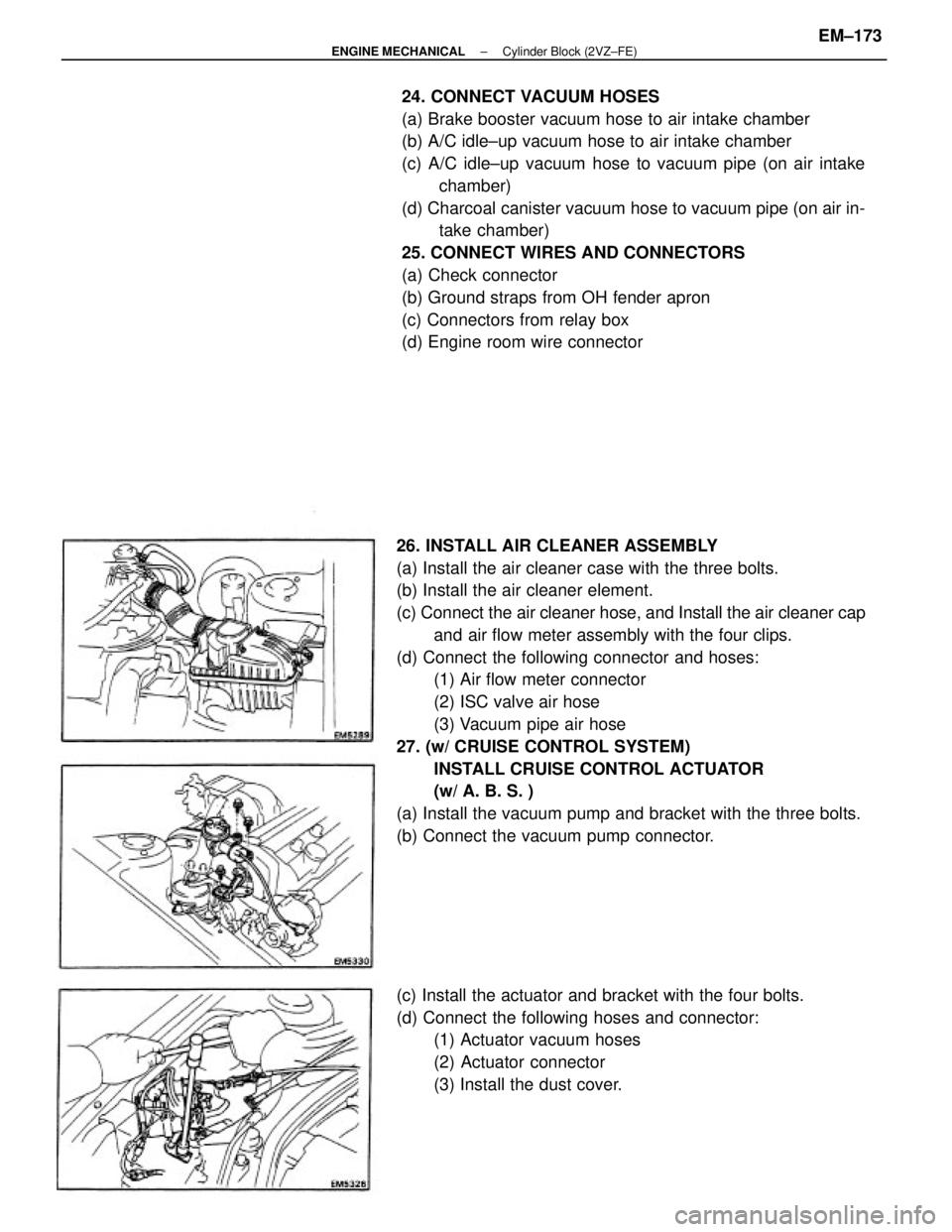
26. INSTALL AIR CLEANER ASSEMBLY
(a) Install the air cleaner case with the three bolts.
(b) Install the air cleaner element.
(c) Connect the air cleaner hose, and Install the air cleaner cap
and air flow meter assembly with the four clips.
(d) Connect the following connector and hoses:
(1) Air flow meter connector
(2) ISC valve air hose
(3) Vacuum pipe air hose
27. (w/ CRUISE CONTROL SYSTEM)
INSTALL CRUISE CONTROL ACTUATOR
(w/ A. B. S. )
(a) Install the vacuum pump and bracket with the three bolts.
(b) Connect the vacuum pump connector.24. CONNECT VACUUM HOSES
(a) Brake booster vacuum hose to air intake chamber
(b) A/C idle±up vacuum hose to air intake chamber
(c) A/C idle±up vacuum hose to vacuum pipe (on air intake
chamber)
(d) Charcoal canister vacuum hose to vacuum pipe (on air in-
take chamber)
25. CONNECT WIRES AND CONNECTORS
(a) Check connector
(b) Ground straps from OH fender apron
(c) Connectors from relay box
(d) Engine room wire connector
(c) Install the actuator and bracket with the four bolts.
(d) Connect the following hoses and connector:
(1) Actuator vacuum hoses
(2) Actuator connector
(3) Install the dust cover.
± ENGINE MECHANICALCylinder Block (2VZ±FE)EM±173
Page 1365 of 2389
2. REMOVE DISC BRAKE CALIPER
Remove the disc brake caliper from the steering
knuckle, and suspended it with wire.
3. REMOVE ROTOR DISC
4. CHECK BEARING PLAY IN AXIAL DIRECTION
Limit: 0.05 mm (0.0020 in.)
REMOVAL OF FRONT AXLE HUB
1. REMOVE COTTER PIN, LOCK NUT CAP AND
BEARING LOCK NUT
(a) Remove the cotter pin and lock nut cap.
(b) Before removing¿the disc brake caliper, loosen the
bearing lock nut while depressing the brake pedal.
7. DISCONNECT STEERING KNUCKLE FROM LOWER
SUSPENSION ARM
(a) Remove the cotter pin and the nut.
(b) Using SST, disconnect the steering knuckle from the
lower suspension arm.
SST 096 10±55012 5. DISCONNECT TIE ROD END
(a) Remove the cotter pin and nut.
(b) Using SST, disconnect the tie rod end from the steering
knuckle.
SST 09610±55012
6. DISCONNECT STEERING KNUCKLE FROM SHOCK
ABSORBER
Remove two nuts and bolts, and disconnect the steer-
ing knuckle from the shock absorber.
± FRONT AXLE AND SUSPENSIONFront Axle HubFA ± 8